Shimano WH-RX010 Dealer's Manual

Type
Dealer's Manual

This manual is also suitable for

(English)
DM-WH0003-06
Dealer's Manual
ROAD MTB Trekking
City Touring/
Comfort Bike
URBAN SPORT E-BIKE
Cross Bike Wheel Set
WH-RX830
WH-RX31
WH-RX05
WH-RX010
SM-RIMTAPE
2
CONTENTS
IMPORTANT NOTICE .............................................................................................. 3
TO ENSURE SAFETY ............................................................................................... 4
LIST OF TOOLS TO BE USED .................................................................................. 7
INSTALLATION ....................................................................................................... 9
Tire size .........................................................................................................................................................9
Installation of cassette sprocket .................................................................................................................. 9
MAINTENANCE .................................................................................................... 12
Spoke lacing ...............................................................................................................................................12
Replacing the spoke ................................................................................................................................... 15
Pulling out the hub axle ............................................................................................................................17
Disassembly and assembly .........................................................................................................................18
Replacement of the freewheel body ........................................................................................................20
Installing and removing tubeless tires ......................................................................................................23
3
IMPORTANT NOTICE
IMPORTANT NOTICE
This dealer's manual is intended primarily for use by professional bicycle mechanics.
Users who are not professionally trained for bicycle assembly should not attempt to install the components themselves using the dealer's manuals.
If any part of the information on the manual is unclear to you, do not proceed with the installation. Instead, contact your place of purchase or a local
bicycle dealer for their assistance.
Make sure to read all instruction manuals included with the product.
Do not disassemble or modify the product other than as stated in the information contained in this dealer's manual.
All manuals and technical documents are accessible online at https://si.shimano.com.
For consumers who do not have easy access to the internet, please contact a SHIMANO distributor or any of the SHIMANO offices to obtain a hardcopy
of the User's Manual.
Please observe the appropriate rules and regulations of the country, state or region in which you conduct your business as a dealer.
For safety, be sure to read this dealer's manual thoroughly before use, and follow it for correct use.
The following instructions must be observed at all times in order to prevent personal injury and physical damage to equipment and surroundings.
The instructions are classified according to the degree of danger or damage which may occur if the product is used incorrectly.
DANGER
Failure to follow the instructions will result in death or serious injury.
WARNING
Failure to follow the instructions could result in death or serious injury.
CAUTION
Failure to follow the instructions could cause personal injury or physical damage to equipment and surroundings.
4
TO ENSURE SAFETY
TO ENSURE SAFETY
WARNING
Be sure to follow the instructions provided in the manuals when installing the product.
Only use SHIMANO genuine parts. If a component or replacement part is incorrectly assembled or adjusted, it can lead to component failure and cause
the rider to lose control and crash.
Wear approved eye protection while performing maintenance tasks such as replacing components.
Be sure to also inform users of the following:
Check that the wheels are fastened securely before riding the bicycle. If the wheels are loose in any way, they may come off the
bicycle and cause serious injury.
Do not use this wheel set for rigorous activities such as competitions. This wheel set is designed for recreational use. The wheel may break, and you
may fall.
Inspect the wheels before riding the bicycle to check for broken or loose spokes and dents, damage, or cracks in the rim surface. Do not use the bicycle
if any of these symptoms are found. Doing so may cause damage to the wheels and result in a fall. Also check for symptoms such as carbon peeling
and cracking.
If the quick release mechanism is not used correctly, the wheel may come off the bicycle and serious injury could result. Read the instruction manual
for the quick release mechanism thoroughly before use.
Do not use the wheels with a rim brake. These wheels are designed exclusively for use with disc brakes. They do not support rim brakes.
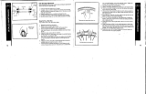
Make sure that even if the axle release lever is tightened as much as possible by hand, the axle release
lever does not interfere with the disc brake rotor. If the axle release lever is on the same side as the
disc brake rotor, there is a possibility they may interfere. If the lever interferes with the disc brake
rotor, stop using the wheel and consult a dealer or an agency.
Quick release lever
Disc brake rotor
CAUTION
Be sure to also inform users of the following:
Use rim tape which can withstand high pressure, otherwise the tires may suddenly puncture and come off, which may result in severe injury.
Furthermore, do not reuse rim tape after it has been removed from the wheel. If you use rim tape without fully understanding the characteristics of
rim tape, the tires may suddenly puncture and come off, and severe injury may result.
When you replace the rim tape, use the one that matches the rim size. If you use a rim tape that does not match the rim size, a sudden puncture may
occur, and you may fall off the bicycle.
The tires should be inflated to the appropriate pressure indicated on the tires before use.
When using a puncture repair agent, consult a dealer or an agency.
Burn-in period
Disc brakes have a burn-in period, and the braking force will gradually increase as the burn-in period progresses. Make sure that you are aware of any
such increases in braking force when using the brakes during the burn-in period. The same thing will happen when the brake pads or disc brake rotor
are replaced.
5
TO ENSURE SAFETY
NOTICE
Be sure to also inform users of the following:
Do not lubricate the internal parts of the hub. Otherwise, grease will flow out.
It is recommended that you ask a bicycle dealer to adjust the spoke tensions if there is any deviation in the spokes and after the first 1,000 km of
riding.
Do not use detergent or other chemicals when wiping the wheel, otherwise the sticker on the rim or the paint may come off.
Products are not guaranteed against natural wear and deterioration from normal use and aging.
For maximum performance we highly recommend SHIMANO lubricants and maintenance products.
For Installation to the Bicycle, and Maintenance:
Use of genuine SHIMANO spokes and nipples is strongly recommended. If non-SHIMANO parts are used, the area where the spokes fit into the hub
unit may become damaged.
If the wheel becomes stiff and difficult to turn, lubricate it with grease.
For compatible reflectors and spoke protectors, check the specifications table (https://si.shimano.com).
The actual product may differ from the illustration because this manual is intended mainly to explain the procedures for using
the product.
LIST OF TOOLS TO BE USED
7
LIST OF TOOLS TO BE USED
The following tools are required to assemble the product.
Tool Tool Tool
5 mm hexagon wrench 13 mm hub spanner TL-LR15
10 mm hexagon wrench 15 mm hub spanner
TL-SR21
14 mm hexagon wrench 17 mm hub spanner
Spoke plug wrench Adjustable wrench
INSTALLATION
9
INSTALLATION
Tire size
INSTALLATION
Tire size
The recommended tire sizes for installation to each wheel are as follows.
Model No. Tire size
WH-RX830
WH-RX31
WH-RX05
WH-RX010
(622) 25C-38C
Installation of cassette sprocket
For each sprocket, the surface that has the group mark should face outward and be positioned so that the wide parts of the gear projections on each
sprocket and the (x) part (where the groove width is wide) of the freewheel body are aligned.
For installation of the HG sprockets, use the SHIMANO original tool TL-LR15 to tighten the
lock ring.
To replace the HG sprockets, use the SHIMANO original tool TL-LR15 and TL-SR21 to
remove the lock ring.
(x)
The groove has only one wide
section.
(y)
Wide part
(z)
Disassembly
(A)
Lock ring spacer
(B)
Lock ring
(C)
TL-LR15
(D)
TL-SR21
Tightening torque
30 - 50 N·m
(B)(A)
(x)
(B)
(D)(C)
(z)
(y)
*
The illustration of the cassette sprocket is an example. For details, refer to the dealer's manual or user's manual of the cassette sprocket to be used.
10
INSTALLATION
Installation of cassette sprocket
< WH-RX830 / WH-RX31 / WH-RX010 >
NOTICE
When installing a 10-speed cassette:
Install the included 1.85 mm low spacer at the position indicated in the figure.
CS-7900/CS-7800/CS-6700/CS-6600/CS-5700/CS-5600:
A 1.0 mm spacer is included with the cassette. Install it.
Sprocket spacers
Lock ring
1.0 mm
spacer
Low spacer
(1.85 mm)
Groove: Sprocket side
*
Some 1.85 mm low spacers do not have
grooves.
*
Refer to the Disc Brake section of General Operations for installation of the disc brake rotor.
MAINTENANCE
12
MAINTENANCE
Spoke lacing
MAINTENANCE
Spoke lacing
Lace the spokes as shown in the illustration.
WH-RX830
Number of spokes: 24
For front
Left side Right side
For rear
Left side Right side
Spoke tension value
For front For rear
Right side Left (disc brake rotor) side Right (sprocket) side Left (disc brake rotor) side
600 - 1,000 N 800 - 1,350 N 900 - 1,350 N 600 - 900 N
* These values should be used as a guide only.
13
MAINTENANCE
Spoke lacing
WH-RX31
Number of spokes: 24
For front
Left side Right side
For rear
Left side Right side
Spoke tension value
For front For rear
Right side Left (disc brake rotor) side Right (sprocket) side Left (disc brake rotor) side
600 - 900 N 900 - 1,300 N 1,000 - 1,400 N 600 - 900 N
* These values should be used as a guide only.
14
MAINTENANCE
Spoke lacing
WH-RX05 / WH-RX010
Number of spokes: 28
For front For rear
Spoke tension value
For front For rear
Right side Left (disc brake rotor) side Right (sprocket) side Left (disc brake rotor) side
<WH-RX05>
450 - 800 N
<WH-RX010>
500 - 850 N
< 1400 N
(MAX-MIN ≤ 400 N)
< 1400 N
(MAX-MIN ≤ 400 N)
<WH-RX05>
450 - 800 N
<WH-RX010>
500 - 836 N
* These values should be used as a guide only.
15
MAINTENANCE
Replacing the spoke
Replacing the spoke
Install the spokes by inserting them through the hub as shown in the illustration.
WH-RX830
1
(A)
(C)
(B)
(D)
Pass the washer and spoke plug over the
spoke.
After inserting the spoke into the hole in
the hub flange, tighten the hub nut.
When installing, use the spoke stopper
to secure the spoke so that it does not
turn, and then insert a screwdriver or
similar tool into the groove in the hub
nut to screw in the hub nut.
(A)
Spoke
(B)
Washer
(C)
Spoke plug
(D)
Hub nut
NOTICE
If the washer is not installed, it will not be
possible to adjust the spoke tension, so be
sure to include the washer.
Tighten the hub nut as far as the edges of
the thread.
2
(A)
Turn the spoke plug clockwise to screw it
into the screw hole in the rim. At this
time, use the spoke stopper to stop the
spoke from turning.
(A)
Spoke stopper
WH-RX31
(B)
(A)
(A)
Spoke
(B)
Nipple
16
MAINTENANCE
Replacing the spoke
WH-RX05 / WH-RX010
(B)
(A)
(A)
Spoke
(B)
Nipple
(B)
(A)
(A)
Spoke
(B)
Nipple
17
MAINTENANCE
Pulling out the hub axle
WH-RX31 / WH-RX05 / WH-RX010
1
(A)
(z)
(B)
(z)
Disassembly
(A)
13 mm hub spanner (Front)
15 mm hub spanner (Rear)
(B)
17 mm hub spanner
Tightening torque
15 - 17 N·m
2
(A)
(B)
(C)
(D)
(A)
Lock nut
(B)
Washer
(C)
Axle spacer
(D)
Cone
3
(A)
*
The illustration shows the rear side.
(A)
Hub axle
18
MAINTENANCE
Disassembly and assembly
WH-RX830-TL-F
< Disassembly >
These units can be disassembled as shown in the illustration. Grease should be reapplied to each part at periodic intervals.
Apply grease
(A)
(C)
(B)
(A)
Dust cover
(B)
Seal
(C)
Premium Grease (Y-04110000)
NOTICE
The front hub cannot be disassembled from
the left side of the hub unit (the disc brake
rotor fixing spline side).
When removing and installing the seal, do
it very carefully so that the seal does not
become bent. When reinstalling the seal,
make sure that it is facing the right way,
and insert it as far as it will go.
Do not disassemble the dust cover which is
crimped onto the hub axle.
< Assembly >
Use the 17 mm hub spanner for installing the hub axle and a 5 mm hexagon wrench to tighten the lock nut so as to double-lock the mechanism as
shown in the illustration.
(A)
(B)
(z)
(C)
(z)
Tighten
(A)
Hub axle
(B)
5 mm hexagon wrench
(C)
17 mm hub spanner
Tightening torque
15 - 17 N·m
19
MAINTENANCE
Disassembly and assembly
WH-RX830-TL-R
< Disassembly >
These units can be disassembled as shown in the illustration. Grease should be reapplied to each part at periodic intervals.
(C)
(C)
(B)
(A)
Apply grease
Apply grease
(A)
Cone with dust cover
(Cannot be disassembled)
(B)
Seal (Lip is on the outside)
(C)
Premium Grease (Y-04110000)
NOTICE
When removing and installing the seal, do
it very carefully so that the seal does not
become bent. When reinstalling the seal,
make sure that it is facing the right way,
and insert it as far as it will go.
Do not disassemble the dust cover which is
crimped onto the cone.
Do not attempt to disassemble the
freewheel body, because it may result in a
malfunction.
< Assembly >
Use the 17 mm hub spanner for installing the hub axle and a 5 mm hexagon wrench to tighten the lock nut so as to double-lock the mechanism as
shown in the illustration.
(B)
(z)
(C)
(A)
(z)
Tighten
(A)
Hub axle
(B)
5 mm hexagon wrench
(C)
17 mm hub spanner
Tightening torque
15 - 20 N·m
20
To be continued on next page
MAINTENANCE
Replacement of the freewheel body
WH-RX830-TL
1
(A)
(z)
(B)
(C)
(D)
(E)
First, pull out the hub axle by following
the procedure shown in the illustration.
The double-lock section at the freewheel
side cannot be disassembled.
(z)
Disassembly
(A)
5 mm hexagon wrench
(B)
17 mm hub spanner
(C)
Cone with dust cover
(Cannot be disassembled)
(D)
Disc brake rotor fixing spline
(E)
Hub axle
Tightening torque < Assembly >
15 - 20 N·m
NOTICE
Do not disassemble the dust cover which is
crimped onto the cone.
  • Page 1 1
  • Page 2 2
  • Page 3 3
  • Page 4 4
  • Page 5 5
  • Page 6 6
  • Page 7 7
  • Page 8 8
  • Page 9 9
  • Page 10 10
  • Page 11 11
  • Page 12 12
  • Page 13 13
  • Page 14 14
  • Page 15 15
  • Page 16 16
  • Page 17 17
  • Page 18 18
  • Page 19 19
  • Page 20 20
  • Page 21 21
  • Page 22 22
  • Page 23 23
  • Page 24 24
  • Page 25 25
  • Page 26 26

Shimano WH-RX010 Dealer's Manual

Type
Dealer's Manual
This manual is also suitable for

Ask a question and I''ll find the answer in the document

Finding information in a document is now easier with AI