Page is loading ...

WORKSHOP MANUAL
JAWA 350/638,639,640
JAWA Moto spol. s r.o. Týnec nad Sázavou
2004

2
WORKSHOP MANUAL
___________________________________________________________________________
The purpose of this Manual, intended primary for specialized Jawa repair shops, is to
facilitate all jobs connected with repairs of Jawa 350 motorcycles. All the described
dismantling, refitting and adjusting procedures have been elaborated under the assumption,
that the reccomended tools and special jigs and fixtures will be used for them. All
information, illustrations and technical data contained in this manual are based on the latest
knowledge gained in and during manufacture. The Jawa Moto spol. s r.o. reserves the right to
change its products any time without a previous notice. Any changes and or deviations from
the standard version for certain territories will be published in the form of Supplements to this
Manual. It is not permited to reproduce this Workshop manual or its parts in any form
whatsoever without written consent.

3
WORKSHOP MANUAL
___________________________________________________________________________
PRE-SALE SERVICE
1. Unpack the motorcycle, free it from preservation grease, assemble the separately
delivered units and parts of accessories /control of completeness/.
2. Check engine and frame numbers – to be conform with the documentation.
3. Take out the accumulator – charging – forming, assemnbly.
4. Control the oil level in the gearbox – refilling.
5. Control all the functions of electrical accessories.
6. Basic adjustment of the headlight /page 50 operating instructions/ and vertification of
headlight tilting.
7. Check ignition – spacing between catcher and rotor.
8. Adjustment of coupling.
9. Adjustment of brakes. /idle run, dearate front, clearance of stop switch cable/
10. Filling the machine with min. 1 liter of petrol – lubricated 1:50 and starting the
engine. (Motos without Oil-master) By motorcycles with Oil-master – filling in oil,
deaerate whole systém, filling in petrol and starting.
11. Adjusting the idle run on warm engine, retightening of cylinderheads and exhaust
elbows.
12. Control of bolted connections.
13. Instructions about attendance of machine and handing over to the customer.
TECHNICAL DATA
DIMENSIONS OF MOTORCYCLE Length 2100 +/- 30 mm
Width 780 +/- 15 mm
Height 1160 +/- 30 mm
Clearance 120 +/- 10 mm
Seat height 820+/- 15mm
Axle base 1370 +/- 25 mm
Min. turn radius 3,5 +/- 0,4 m
MASS AND LOAD Proper mass 149 +/- 3 kg
Running mass 162 +/- 3 kg
Overall mass 342 +/- 3 kg
Payload 180 kg
Nr. of seats 2
Trailer mass 50 kg overall
Sidecar mass 172 kg overall
ENGINE Category two-stroke, air-cooled
Nr. of cylinders 2
Cylinder capacity 343,5 ccm
Bore 58 mm
Stroke 65 mm
Compression ratio 9,8 + 0,7 :1
- 0,3 :1
Max revs. 5750 / 1 min
Max output 17 kW–10% -5250/1 min +/- 3%
Max torque 32 Nm–6% - 4750/1 min +/- 5%
CARBURETOR Class Jikov 28-29 CE horizontal
Slide type
CLUTCH Type multiple-disc in oil bath

4
WORKSHOP MANUAL
___________________________________________________________________________
GEARBOX Type mechanical with gears,
double shaft
Number of gears 4
Control by foot lever
Overall ratio climbing capacity with full load
1.st gear 1 : 14,50 41%
2.nd gear 1 : 8,60 20%
3.rd gear 1 : 6,10 14%
4.th gear 1 : 4,96 9,5 %
primary chain 2 x 9,525 x 4,7766 links
secondary chain 1 x 12,7 x 7,75 126 links
+1 conect
SUSPENSION Front telescopic fork, steel spiral
springs
Stroke 150 mm – wheel axle 134 mm
Rear swing arm, spiral springs
Stroke 80 mm – whell axle 90 mm
Front shock absorber hydraulic
Type telescopic in fork´s arms
Rear shock absorber hydraulic
Type telescopic in suspension units
RIMS Front wheel steel, deepened profile
Dimensions 2,15 B x 18“
Rear wheel steel, deepened profile
Dimensions 2,15 B x 18“
BRAKES Front disc type, hydraulic control
Dimensions ø 265 mm
Rear drum, mechanic control
Dimensions ø 165 mm
ELECTRIC OUTFIT Ignition magneto VAPE A67 contactless
Output 12 V, 180 W
Battery lead type, 12 V, 6 Ah
Headlamp asymmetrical, rectangular,
adjustable
12 V – 60/55 W
12 V – 4 W BA 9s
Dip switch sliding type
Indicators switch lever type
Tail lamp group type
Indicators location headlamp bracket
rear frame
FUEL AND LUBRICANTS Fuel tank capacity 17 l, 2,8 l reserve
Gearbox – oil charge 1+0,1 l
Suspension – oil charge
Front 200 ccm per arm
Rear 47 ccm per absorber
permanent charge
Front brake brake fluid DOT 4 to max.
(upper edge of window)
FRAME Type tubular, double, closed

5
WORKSHOP MANUAL
___________________________________________________________________________
LIST OF REPAIR TOOLS FOR TYPE 638, 639, 640
1
2
3
4
5
6
7
8
9
10
11
12
13
14
15
16
17
18
19

6
WORKSHOP MANUAL
___________________________________________________________________________
LIST OF REPAIR TOOLS FOR TYPE 638, 639, 640
ITE
M
NR.
TYPE
DESIG.
SERIAL NR. QUAN
TITY
DESCRIPTION
1 S-46 9.71.51559.4 1 Feeler gauge for ignition advance adjustment
2 S-97 9.71.880097 1 Drag (for rotor)
3 S-63 9.71.51589.4 1 Pawl retsiner
4 S-64 9.71.515590.4 1 Drift, centering bushes
5 S-71 9.71.51577.4 1 Drift for driving out bearings
6 S-72 9.71.51576.4 1 Drift for driving home sealing rings
7 S-81 16-19758-4 1 Tubular spaNner – steering head
8 S-85 9.71.52248.4 1 Drag, removing primary sprocket
9 S-86 9.71.52253.4 1 Drift dia
10 S-87 9.71.52252.4 1 Mandrel for gudgeon pin preSsing dia. 16 in and out
11 S-88 9.71.52251.4 1 AuxilIary bush, connecting rod small end
12 S-90 28-86-763 1 Jig with bolts for separating crankcase halves
13 S-66 9.71.51603.3 1 AuxilIary clutch plate
14 S-92 28-86-765 1 Drift
15 S-93 28-86-766 1 Fork leg extractor
16 S-94 28-86-814 1 Primar chain adapter
17 S-201 9.96.55407.3 1 Lever
18 S-203 28-86-767 1 Pliers
19 S-205 28-86-725-2 1 Pressing jig with accessories
List of lubricants recommended for motorcycle JAWA 350
Use of oil type of oil in the Czech rep. Viscosity Class notes
A gearbox Mogul Trans 90 API GL 4
temperature over 0°C
brake lever pins Gyrol 90 SAE 90
clutch lever pins
brake cams Mogul Trans 80W/90API GL 4 whole year
stand pins
bowden cables Byrol 80W/90 SAE 80W/90
B engine lubrication
B1 lubricated petrol Mixture ratio 1:60 – after running in, 1:50 during running in
For whole year riding use oil of viscosity class SAE 30-40 for two stroke engines and
with classification according to API TS.
B2 Lubrication with Oil–master systemFor whole year riding use prediluted or syntetic
oil for two stroke engines according to recommendation of individual oil producers.
For riding in temperatures over 0°C can be used oil for two strokes engines of
viscosity class SAE 30-40 and with classification according to API-TC.

7
WORKSHOP MANUAL
___________________________________________________________________________
C Telescopic front fork Mogul Super 15W/40 API SD/CB or
Mogul Super stabil API SF/CC
15W/40 SAE 15W/40
D accelerator twist grip energrease LA2 ISO-L-XBCEB 2
Swinging rear arm energrease LA2 ISO-L-XBCEB 2
E rear sprocket bearings energrease LA2 ISO-L-XBCEB 2
F wheel bearings energrease LA2 ISO-L-XBCEB 2
G secondary chain special spray e.g. Castrolů Mo S2, Gleitmo 582 ……..
OPERATING LIQUIDS TYPE OF LIQUID IN CZ CLASSIFICATION
A brake fluid Syntol HD 260 DOT 4
Maintenance plan
km
500
1500
2500
5000
10000
15000
20000
25000
30000
Transmission oil * V V K V K V K V
Clutch * K K K K K K K
V
K
Carburettor S
Air filter *** K K K V K K V
Steering head K K M K K
M
Rear suspension V K
Secondary chain K K K M K V M K V
Wheels and rear suspension bearings M M M
Brakes – brake lining K K K
Bowden cables **** K K K K K K
Battery K K K K K K K K V
Alternator K K
Ignition spacing - between rotor and catcher S K K K S K S K S
Spark plugs C V V
Front fork – oil exchange **** V V V V V V V
Wheels – spokes stretching K
Brake lever pins, joints, stop switches, accelerator twist grip * K K K K K K K K
Piston, piston rings, transfer ports K K
Brake plate K K K V K K V
Screws, nuts and packings *** K K K K K K K K K
* check as often as necessary K checking, cleaning, adjusting or eventually replacement
** check every 1000 km C cleaning
*** check every 2500 km S adjustment
**** check every 5000 km M lubrication
V replacement D decarbonization
After running of:
25 000 km primary chain replacement
30 000 km check or exchange of connecting rod bearings, steering head bearings, shaft type gasket rings
with the crankshaft as well as wheel with hub, wear of cylinder (event. re-bore)
50 000 km complete dismantling of brake system

8
WORKSHOP MANUAL
___________________________________________________________________________
List of main bearings and sealing rings
Designation name of part pcs. positin
324 594 043 400 needle bearing INA HN (15x22x12)1 engine – leftt side
324 163 030 100 bearing 6303 A 1 engine – leftt side
324 163 059 566 bearing 6305 A 1 engine – leftt side
324 594 049 200 needle bearing INA BN (16x22x12)1 engine – right side
324 232 050 000 bearing 3205 1 engine – right side
324 232 050 003 bearing 3205 C 3 1 engine – right side
324 162 069 566 bearing 6206 2 ckrankshaft
273 521 008 617 sealing ring (30x52x10) 1 engine – right side
273 521 106 807 sealing ring (25x52x7) 1 engine – right side
273 521 006 917 sealing ring (25x62x8) 1 engine – leftt side
273 521 100 417 sealing ring (8x16x7) 1 speedometer drive
324 914 010 452 ball (Ø 6,35) 1+36 frame head, clutch release
324 163 020 100 bearing 6302 A 2+2 front and rear wheel
324 162 050 100 bearing 6205 A 1 rear wheel sprocket

9
WORKSHOP MANUAL
___________________________________________________________________________
Piston grading
Grading D 2
+ 0,000
- 0,010
Standard A 57,972
B 57,982
C 57,992
1. re-bore A 58,222
B 58,232
C 58,242
2. re-bore A 58,472
B 58,482
C 58,492
3. re-bore A 58,722
B 58,732
C 58,742
4. re-bore A 58,972
B 58,982
C 58,992
Cylinder grading
Note: The manufacturer delivers spare cylinders exclusively with the basic /standardú bore.
The other dimensions given in the table are guides for cylinder reboring. As it is very difficult
to rebore the cylinders accurately within the tolerance limits of hundredths of millimeters, it is
necessary to check the bore of the rebored cylinder by measuring it at several points, and to
use a piston of grading corresponding to the measured dimension. The grading mark on the
top face of the cylinder has to be changed accordingly.
In the engines (new or rebored) the right-hand and left-
hand may be of a different grading class (but not of
different rebore grading). In the case of cylinders with
rebores in between of two grading groups, it is possible
to use a piston of B or C group. With the B piston is
running in quicker, with C piston nocking is likely on
cold engine (after start).
Standard
Grading D1 D2 D3 I.re-bore II.re-bore III.re-bore IV.re-bore
A
58,01+0,01 58,01+0,01 58,01+0,02
B
58,02+0,01 58,02+0,01 58,02+0,02
C
58,03+0,01 58,03+0,01 58,03+0,02
D
58,04+0,01 58,04+0,01 58,04+0,02
+0,25 +0,5 +0,75 +1,00

10
WORKSHOP MANUAL
___________________________________________________________________________
List of gudgeon-pin bearings
Connecting rod Gudgeon pin Needle roller
Ø 2 x 13,8
Clearance
Red
19,994+19,998
Blue
15,994+15,997
1,994+1,996
1,993+1,995
0,005+0,016
0,007+0,018
Red
15,997+16,000
1,994+1,996
1,993+1,995
0,006+0,017
0,008+0,019Blue
19,998+20,002
Blue
15,994+15,997
1,996+1,998
1,995+1,997
0,005+0,016
0,007+0,018
Blue
15,997+16,000
1,996+1,998
1,995+1,997
0,006+0,017
0,008+0,019White
20,002+20,006
Blue
15,994+15,997
1,998+2,000
1,997+1,999
0,005+0,016
0,007+0,018
Yellow
20,006+20,010
Red
15,997+16,000
1,998+2,000
1,997+1,999
0,006+0,017
0,008+0,019
I. ENGINE
1.1. Disassembly and Assembly of the Cylinder Head and Cylinder
Prior to disassembly take out
the carburettor flange, wich is
shared by both cylinders.
Using the box spanner loosen
and remove the eight M10 nuts to be
able to loosen and remove the
cylinder heads. Rotate the engine
until the piston of cylinder which
should be removed is in the bottom
dead center. Take out the cylinder
and cover the ensuing holes to avoid
drain of dirt. For assembly proceed
in opossite sequence. Clean the
cylinder and engine housing seating
surfaces before assembly. Oil the
cleaned cylinder working surface
and put it on the piston. During the
assembly proceed with caution,
check if piston rings sit right in the
joints to protect them from damage.
Fit new sealing under cylinderheads (in case the old is damaged). Screw the head bolts nuts home crosswise

11
WORKSHOP MANUAL
___________________________________________________________________________
using the torque spanner at the force
of 17,6 Nm. If the engine is
mounted in the frame, first remove
seat and tank, separate the exhaust
elbows and disconnect the coils,
cables and cable shoes.
1.2. Pistons – demounting and mounting
Since the piston is mounted in the
cageless needle bearing, use special tools for
demounting the piston.
There is a danger that some needles
may fall into the engine internals. This may
result into heavy damage of engine and would
be necessary to dismantle the engine and find
strayed needles. The following procedure is
reccomendable:
Take off the cylinders ( see sect. 1.1),
plug the crankcase holes, remove piston rings
and using suitable plies remove piston pin
locks.
Fit the auxiliary insert S-88 into the
piston opening and the press-out pin in the
auxiliary insert. Push the pin as far as the pin
support surface. Detach the piston from the
piston rod top end and lock the auxilary insert
S-88 (held between the needles in the piston
rod end). And the two original take-up rings to
avoid their falling down.
Prior to proceeding to mounting the
pistons, make sure that all needle rollers (28
units per rod) and the take-up rings are fitted
in the connecting rod top ends. The auxiliary
inserts S-88 must be mounted inside the
rollers. When fitting a piston on the connecting
rod top end, make sure that take-up rings and
rollers do not fall into the engine housing
internals

12
WORKSHOP MANUAL
___________________________________________________________________________
Piston must have signing L (left side)
or P (right side) for the corresponding cylinder
and the arrow must be oriented forward to the
exhaust ports. Use the press-out pin S-87 to
push the piston pins. Make sure, that the
lightening holes of the piston pins are oriented
to the engine outside. Lock the piston pins
with lock rings. When mounting new pistons,
check if their identification marks (i.e. A,B,C)
correspond to each cylinder.
Make this check before mounting the
piston rings to be sure that the piston in the
cylinder is not off the axis: fit the piston
(without rings) provisionally on the piston and
turn the crank mechanism with the starting
lever to see if the piston have the identical
clearance on each side when it is in the top
dead end position.
If it leans permanently against one side and,
when pushed off, returns to the original position,
take the cylinder out and bend with caution the
connecting rod with piston to the other side. This
act is called „connecting rod angle adjusting“.
The truly adjusted connecting rod must have the
identical play on each side.

13
WORKSHOP MANUAL
___________________________________________________________________________
1.3. Primary gear, clutch - dissasebly
CAUTION: First drain oil from the gearbox.
Take off the starting lever (first move it to the
star position) and remove the bolts holding the
left engine cover. After compressing the
springs take off the clutch pins, dismantle the
washers and springs and plates and insert the
securing plate S-66 into the clutch drum.
With barrel spanner nr.19 remove the nut M12
and take off the inner clutch drum.
With barrel spanner nr. 27 loosen the primary
gear nut. Using S-85 puller remove this
primary gear and take it together with the
clutch cage and chain off the shafts.
In most of the cases you may remove the
clutch cage without having to strip the primary
chain wheel, while moving a few times the
clutch cage on the mainshaft and releasing
thus the clutch gear spacer. Grip the released
spacer and pull it out and remove the cage.
1.3.1. Assembly
Fit the primary chain gear on the clean,
dry crankshaft taper and the washer and spacer
(test the run out rate of the spacer faces before the
assembly) on the mainshaft. Place a steel ruler on
the gear flank against the gears to make sure that
both gears are alligned (admissible tolerance is of
0,5 mm).
The true alignment is important for primary chain
lifetime expectancy and the primary gear noise
rate. To eliminate the deviations (if any) of the
clutch chain gear fit steel shimp of adequate
thickness on the mainshaft between the bearing
and the washer. Test the parallelity and take off
the clutch gear again. Before mounting the
starting gear check the condition of the shaft seal
ring. Mount the starting gear (move the shaft for
the purpose to be in the starting position). Fit the
primary chain on the chain gear crankshaft taper
and crankshaft. Put on the inner clutch drum
(with fitted undamaged lock washer) on the
mainshaft. Fix the carrier with nut and lock the
washer. Screw home the primary chain gear nut
on the crankshaft For the job use the S-66 jig.

14
WORKSHOP MANUAL
___________________________________________________________________________
1.4. Clutch - assembly
Fit the oiled clutch rod with rest in the mainshaft. On the outer drum put one by one the
friction and steel discs. If we change the plates, before the assembly, measure their overall
thickness, wich should be 18,25 +/- 19 mm (5 plates). Put on pressure plate with springs and
washers over them. Compress successively the spring over washes with spanner nr. 10 and
over the washers fix the securing pins. The tightening torque of the M12x1,25 nut holding the
clutch is 35-40 Nm.
1.5 Speedometer drive and sealing
Dismount the primary gear as described under 1.3. Unscrew the M6 bolt
provided on the engine bottom and holding the speedometer drive socket and
take it out of the engine. Unscrew the grub screw from the lug provided on
engine housing inner bottom (the screw drives the speedometer). Using a
stick (preferably an aluminium one) knock the drive casing and the seal ring
into the housing space. For mounting, fit the new 8x16x7 seal ring on the
drive shaft (spring should face the engine internals), and using a suitable pipe
or socket wrench of 15 mm outer diameter tap on the drive to push it through
the housing to its seat as far as the point when groove on the drive surface is
in the line with the thread for the lock screw in the housing. Once a screw is
screwed home, drift it with centre punch

15
WORKSHOP MANUAL
___________________________________________________________________________
1.6. Starter spring
(primary gear dismounted)
Turn the starter shaft to the left and take it
out of its mounting Take off the starter
segment and spring. When remounting the
spring, fit its one end on the segment edge.
Turn the segment to get it in its true position,
with the segment hole centre aligned with the
carrier hole center. The other end of the
spring sits on the enginehousing rear wall. Fit
in the starter shaft (with spring) and turn it to
get it in the starting position.
1.7. Shaft with carrier
Gearshift pawl
(primary gear dismounted)
Turn the starter shaft and take it
off along with the starter segment and
return spring. Drive out the pin which
holds the clutch-disengagement cam on
the shaft (from the bottom to up) and
remove the cam. Fit the pawl holder S-
63 between the gate and the pawls and
pull with caution the shifter shaft with
carrier and pawls out of the mounting.
When remounting the set, support the S-
63 holder against the carrier pawl and fit
the oiled shaft in its mounting. See that
the carrier pin sits truly between the
return springs in the gate. Mount semi-
automatic set of the clutch on the engine
right hand flank. Then proceed as
described under .
1.8. Dismounting the semi-
automatic clutch
disengagement set.
Adjusting
Loosen the nut and remove the
brake pedal. Remove the engine cover.
Using the spanner 10 unbolt three bolts
and remove the holder. Also unhook the
clutch bowden. For remounting proceed
in reverse sequence.
Note: After remounting the semi-
automatic clutch disengagement set, you
have to adjust it – see chap. 1.

16
WORKSHOP MANUAL
___________________________________________________________________________
1.9. Adjusting of semi-automatic
clutch disengagement set
• Remove the right engine cover
• Screw home the clutch cable adjusting bolts
on bowden (make bowden shorter) to loosen
the cable socket on clutch control set.
• Adjust the play between the foot clutch
disengagement cam and the disengagement
roller with the clutch disengagement bolt M8
to make them touch. (the play between set
bolt and control pole is 0,1 – 0,3 mm)
• Eliminate the play on the clutch lever on
handlebar by adjusting bowden bolts.
1.10. Rear wheel sprocket
Removing and refitting
Remove the semi-auto clutch
release device. Loosen the clips of the rubber
chain guards and lift off the outer cover of the
secondary sprocket. Unlock the lock washer
under the nut. With the slack secondary chain ,
pull the secondary sprocket with the chain and
inner cover out of its bearings. It is not
necessary to disconnect the chain . Reverse
this procedure to refit it back.
Note:
Be carefull when refitting the secondary
sprocket. It must slide easily on the splines. Do
not drive the sprocket forcefully into the
bearing (inside the crankcase) in spite of its
being secured against normal stressing with a
buttress plate. There is danger of serious
damage to the gear shaft forks and gears of
gearbox.
1.11. Take out the engine from the frame
Take off the saddle, disconnect the battery fuse and take off the spark plugs caps. Detach the
fuel supply hose remove the fuel tank, unscrew the carburettor cap and take off the bowden
with the slide. Remove the M8 nut holding the exhaust bent flanges and turn the bents to the
side, so they would not be in the way. Detach the tachometer drive provided below the engine
and the speedometer. Remove the right engine cover, detach the alternator cables. Dismount
rotor using jig S-97. After screwing off four bolts M6 remove alternator stator. Detach the
cable from the idling gear contact and pull the whole cable bundle out of holder in the engine
case. Detach the bowden cable from the clutch automatic set, unscrew the three bolts and
remove the control set of clutch. Loosen the rear wheel axis and the transmission gear nut.
Loosen the chain tensioner and move the wheel forward to remove the chain.

17
WORKSHOP MANUAL
____________________________________________________________________________
Take off the outer cover sprocket, loosen
the gear nut and unscrew with nr.32 socket
spanner. Pull out the sprocket with inner
cover from mounting.
It is not necessary to uncouple the chain.
Remove the right footrest, bolts and pins
holding engine into the frame. Standing on
the right side grip the engine with right
hand by the cylinder and with left hand by
the start lever (see pic.) Lift the engine
slightly to the front, shift it to the right and
take it out of the frame. Avoid damaging
the paint – protect frame pipes (e.g. by
rubber tubes).
I
I
I
I
.
.
D
D
I
I
S
S
M
M
O
O
U
U
N
N
T
T
I
I
N
N
G
G
A
A
N
N
D
D
M
M
O
O
U
U
N
N
T
T
I
I
N
N
G
G
T
T
H
H
E
E
E
E
N
N
G
G
I
I
N
N
E
E
H
H
O
O
U
U
S
S
I
I
N
N
G
G
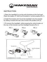
2.1. Basic disassembly
Clamp the engine front section between vice jaws
in such a way, that the engine left side is accesible.
Remove the carburettor, primary gear, cylinder heads
and pistons. Drive the rear centring element from the left
side of engine housing to the right side. Take out the
clutch automatic release device and remove M6 bolts
holding two halves of engine housing together. Take the
housing out of the vice and lay it down on the left side.
2.2. Separating two halves of engine
Bolt the S-90 puller in the M6 thread holes in the
housing (see pic). and strip with it uniformly the
right half of the housing from the crank
mechanism bearing. Take care to keep the right
connecting rod in the top dead end position, it has
to pass easily through the central housing slit. If
during the stripping the right half of housing gets
jammed, knock with caution on the rear poart of
housing event. turn a bit shaft of sprocket to keep
stripping procces uniform. After two halves are
separated enough remove the mid insert between
two cylinders – to allow free passage of
connecting rod. Finish separating and remove the
right half.

18
WORKSHOP MANUAL
___________________________________________________________________________
Suggestion: Use grease (f.ex.PM-NH2, LITOL 24,
CASTROLEASE LH-2 ...) to avoid needles falling out of
countershaft bearings.
2.3. Gearbox – shifting, crank mechanism
With the engine in this dismantled condition, it is
possible to repair the gearbox and the gear shift
mechanism. Without pressing the crankshaft mechanism
out of the other crankcase half. During the inspection of
gearbox and gearshifting, remove the shifter fork rod,
the shifter forks, the layshaft and the gears. With soft
mallet tap the mainshaft out of bearing. If it is necessary
to remove the gear shift plate, remove the four, dot
secured countersink screws from the gate, turn the gate
to suitable position and remove it from case
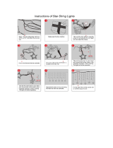
To remove the crankshaft screw the S-85
drag with two M8 screws into the threaded
holes for fastening screws of left half
crankcase cover. Push out the crankshaft out
of left half of case.
Remember: connecting rod must be in its top (T.D.C.)
2.4. Exchange of layshaft needle bearings
After removing locks drive the bearing into the
crankcase with a drift. To facilitate this job, remove the
speedometer drive from left half of engine. Put new
bearings into the crankcase – heat case to 80-120°C.
After pressing them home, fill them up with grease to
avoid loosing of needles.
2.5. Testing the evenness of seating surfaces
Clean thoroughly the seating surfaces and test
the evenness of the whole engine housing with the steel
ruler. Grind the surfaces plain on a plate if necessary.
Clean the ground surfaces thoroughly of the grinding
paste.
2.6. Exchange of bearings and seal rings of
crankshaft mechanism
Change bearings in case they are noisy or worn
out. Dismantle the engine housing, remove the lock rings
of sealing rings. Heat the case up to 100-120°C and using
the drift S-71 drift the bearing into the engine case. Use
drift S-72 to drift out the sealing ring (from inside-out).
Mainshaft bearing drive out similar way.

19
WORKSHOP MANUAL
___________________________________________________________________________
Also after unlocking and driving wheel inside the
case. Mounting of all bearing is realised to heated
case (100-120°C). Put the bearings into the pre-
heated halfs of engine case, getting them inline
with the machined surface intended for the crank
mechanism flywheel. Push the mainshaft and gear
–plus-hub bearing as far as the depth of locking,
wich have to be already in its place. Sealing rings
are mounted in after jointing of case halves.
Lock the mounted mainshaft bearing against
shifting with shims and drift the bolts with centre
punch.
2.6.1. Exchange of sealing rings
The seal rings alone can be replaced while engine is in the frame. However the
primary gear must be dismounted before. Also alternator and chain gear (1.9). Remove the
lock pin and take off the damaged seal ring. Then check the true joint of the spring, oil the
seal rings and drive the latter in place with the S-72 and S-92 jigs.
2.7. Gearbox
For the correct reassembly of gearbox it is
recommended to begin with the crank mechanism
removed from the crankcase halves in order to
ensure the maximum clearance of the layshaft. To
ascertain this clearance, fit the layshaft into
ballbearing together with the 1st. speed gear and
then clamp both crankcase halves together
provisionally with several screws. Move the
layshaft forward and backward to check its axial
clearance which should be in the range from 0 –
0,6 mm. Then remove the layshaft and locate the
crank mechanism with the centre face plate (if
this plate has been removed) into the left
crankcase half heated up to 100-120°C. The
highest temperature has to be around the
crankshaft bearing. Put wooden blocks under the
front and rear part of the crankcase half and insert
the crank mechanism into as fast as possible so
that the lock pin of centre ring fits into the recess
in the crankcase. It is not permitted to drive the
mechanism into the bearing forcefully because
this would result in its „uncentering“ and also in
damaging of bearings. If the crank mechanism
becomes jammed in the baering, drive it out of
the bearing (engine dismantling), reheat the
crankcase and repeat the operation..

20
WORKSHOP MANUAL
___________________________________________________________________________
Set the gear shift gate in one of the centre positions
(extreme positions are unsuitable). Then fit the
mainshaft with the spacer and gear locked in the
position with wireformed ring into the bearing in the
left crankcase half. Fit the 16 tooth gear on the shaft
splines with its three claws pointing downward.
Put shifter fork guide pins into the top and the
bottom slots of the gate and fit the top fork into the 16
tooth gear on the mainshaft at the same time. Then
thread the guide rod through the forks so that its
shouldered end points downward. Locate the 24 tooth
gear with its flat side toward the needle bearing, and
place the 16 tooth gear on the bottom shifter fork with
its three claws pointing upward. Join both gears by the
layshaft with the previously fitted on and secured 19
tooth gear. Check gear shifting by turning the gear
shift gate to the individual positions corresponding to
the individual speeds (especialy if a new gear shift
gate is used) in the following manner.
a) Shift the 1
st
. gear and check whether the
16 tooth gear on the layshaft meshing with
the 1
st
speed gear (24 teeth) has an axial
clearance of at least 0,2-0,3 mm. Likewise
check that, in this position, there is a
clearance between the shifter fork guide pins
and the end of the gate slots.
b) Shift the neutral between 1
st
and 2
nd
gear
and check that the claws of the 16 tooth gear
do not touch the face of 1
st
speed gear and
also the claws of the 2
nd
speed (19 teeth)
gear when lifting in the bottom shifter fork.
c) When shifting in fourth gear, the face of
splined mainshaft should protrude 0,1-0,2
mm from the 3
rd
speed gear (16 teeth). At
the same time check that the shifter fork
guide pins are not abutting against the ends
of the gate slots (see paragraph a).
/