
Installation & Operations Manual
Including Parts Lists
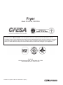
Fryer
Model P16-PF45, P20-PF65
Manual 1189468 Rev 0 (03/07)
$30..00 P16-PF45 & P20-PF65 Fryer
IMPORTANT FOR FUTURE REFERENCE
Please complete this information and retain
this manual for the life of the equipment:
Model #: _________________________
Serial #: _________________________
Date Purchased: _________________

Page 2 Installation & Operations Manual 1189468 Rev 0 (03/07)
THIS MANUAL MUST BE RETAINED FOR FUTURE REFERENCE
FOR YOUR SAFETY
DO NOT store or use gasoline or other flammable vapors or liquids in the vicinity of this or
any other appliance.
WARNING
Improper installation, alteration, service or maintenance can cause property damage,
injury or death. Read the installation, operating and maintenance instructions thoroughly
before installing or servicing this equipment.
TO THE PURCHASER
Post in a prominent location the instructions to be followed in the event that an operator smells gas. Obtain
this information from your local gas supplier.
WARNING
There is an open flame inside the fryer. The unit may get hot enough to set near by materials on fire. Keep
the area around the fryer free from combustibles.
WARNING
DO NOT supply the fryer with a gas that is not indicated on the data plate. If you need to convert the fryer
to another type of fuel, contact your dealer.
WARNING
DO NOT use an open flame to check for gas leaks!
WARNING
Wait 5 minutes before attempting to relight the pilot to allow for any gas in the fryer to dissipate.
WARNING
Never melt blocks of shortening on top of the burner tubes. This will cause a fire, and void your warranty.
WARNING
Water and shortening DO NOT mix. Keep liquids away from hot shortening.
Dropping frozen liquid food into the hot shortening will cause violent boiling.
WARNING
Ensure that the fryer can get enough air to keep the flame burning correctly. If the flame is starved for air,
it can give off a dangerous carbon Monoxide gas. Carbon monoxide is a clear odorless gas that can cause
suffocation.
WARNING
A cooker equipped with casters and a flexible gas line, must be connected to the gas supply with a quick
disconnect device. This quick disconnect must comply with ANSI Z24.41. To limit the movement of the
cooker without depending on the connector or quick disconnect, a restraining cable must also be installed.
NOTICE
Counter top must be constructed of a non-combustible material for counter top fryer installations.

Installation & Operations Manual 1189468 Rev 0 (03/07) Page 3
CHECKING YOUR NEW FRYER
Your new fryer has been carefully packed into one crate. Every effort has been made to ensure that your fryer is delivered
to you in perfect condition. As you unpack your new fryer, inspect each of the pieces for damage. If something is damaged,
DO NOT sign the bill of lading. Contact the shipper immediately, the shipper is only responsible for 15 days after delivery.
Check the packing list enclosed with your fryer to ensure that you have received all of the parts to the fryer. If you are missing
any parts, contact the dealer from whom the fryer was purchased.
CAUTION
To prevent equipment damage, don’t tilt the fryer onto any two of it’s casters or pull the unit by the flue vents.
Leg/Caster Installation and Adjustment
Installing the legs and leveling the fryer is done with a 7/16" wrench, socket, and a large pair of water pump pliers. The legs/
casters must be installed to provide the necessary height to meet sanitation requirements and assure adequate air supply tothe
burner. Attach the legs by performing the following procedure.
a. Lay the fryer on its side being careful not to damage the flue by pulling on it. Protect the outside of the fryer with
cardboard or a drop cloth when laying it down.
b. Attach each leg/caster with the hex head cap screws supplied with the fryer. Each leg/caster requires four 1/4-20 x 5/
8" cap screws.
c. Mount the screws from the inside of the fryer with the nut on the outside. The nuts have lock washers attached to
them, therefore it is not necessary to use lock washers.
d. When all four legs/casters are mounted, stand the unit up being careful not to put too much weight on any one leg/
caster. Adjust the height and level the fryer by adjusting the leveling devices on the leg/caster with the water pump
pliers.
e. On units with casters, move the fryer to the desired location and lock the wheels using the locking devices on the
front of the casters.
WARNING
The fryer must be properly restrained to prevent movement or tipping. This restraint must prevent the fryer from
movements that would splash hot liquids on personnel, which could cause severe burns or injuries.
Always wear oil proof gloves when moving or handling equipment or hot liquids.
Installation Clearances
The fryer needs clearance around it for proper operation. Adequate clearances allow for servicing and proper burner operation.
The clearances shown below are for cooker installation in combustible and noncombustible construction.
Combustible Non-Combustible
Construction Construction
Back 6" 0"
Sides 6" 0"
Floor - Combustible 9" 9" (Needed for Combustion)
Gas Connection
Your fryer will give you peak performance when the gas supply line is of sufficient size to provide the correct gas flow. The
gas line must be installed to meet the local building codes or National Fuel Gas Code ANSI Z223.1 Latest Edition. In Canada,
install the fryer in accordance with CAN/CGA-B149.1 or .2 and local codes. Gas line sizing requirements
can be determined by your local gas company by referring to National Fuel Gas Code, Appendix C, Table C-4 (natural gas)
and Table C-16 (propane). The gas line needs to be large enough to supply the necessary amount of fuel to all appliances
without losing pressure to any appliance.
WARNING
NEVER supply the fryer with a gas that is not indicated on the data plate. Using the incorrect gas type will cause
improper operation. If you need to convert the fryer to another type of fuel, contact your dealer.

Page 4 Installation & Operations Manual 1189468 Rev 0 (03/07)
Fuel Types - Each fryer is equipped to work with one type of fuel. The type of fuel with which the appliance is intended to
operate is stamped on the data plate attached to the inside of the door.
NOTICE
NEVER use an adaptor to make a smaller gas supply line fit the cooker connection. This may
not allow proper gas flow for optimum burner operation, resulting in poor cooker
performance.
Quick Disconnect Gas Connection
Gas fryers equipped with casters must be installed with connectors that comply with the Standard for Connectors for Movable
Gas Appliances, ANSI Z223.1 Latest Edition, and Addenda Z21.69A Latest Edition. This connection should include a quick
disconnect device that complies with the Standard for Quick Disconnect Devices for Use With Gas Fuel , ANSI Z223.1 Latest
Edition. When installing a quick disconnect you must also install a means for limiting the movement of the fryer. This device
will prevent the gas line or the quick disconnect from being strained. The restraining device should be attached to the cooker on
the back panel.
Fuel Supply Line Leak and Pressure Testing
The fuel supply system must be tested before the fryer is used. If the fuel line is going to be tested at a pressure greater than
(>)1/2 PSIG (3.45 kPa), make sure that the fryer is disconnected from the fuel line. If the fuel line is to be tested at a pressure
equal to or less than (<) 1/2 PSIG (3.45 kPa), the fryer can be connected but the unit’s gas valve must be shut. Test all gas line
connections for leaks with a solution of soap and water when pressure is applied.
ELECTRICAL CONNECTION
The electrical service used by the fryer must comply with local codes. If there are no local codes that apply, refer to the National
Electrical Code (NEC), ANSI/NFPA 70 to install the service. In Canada refer to CSA Standard C22.1 and local codes. Wiring
diagrams are provided inside the fryer control box.
Ventilation and Fire Safety Systems
Your new fryer must have proper ventilation to function safely and properly. Exhaust gas temperatures can reach as high as
1000°F. Therefore, it is very important to install a fire safety system. Your ventilation system should be designed to allow for
easy cleaning. Frequent cleaning of the ventilation system and the fryer will reduce the chances of fire. Table 1-2 provides a list
of reference documents that provide guidance on ventilation and fire safety systems. This table is not necessarily complete.
Additional information can be obtained from the CSA-International, 8501 East Pleasant Valley Road, Cleveland, OH 44131.
Excessive ventilation causes drafts, which will interfere with the proper operation of the pilot and the burner. Leave at least 18
inches of open space between the fryer’s flue vent opening and the intake of the exhaust hood.
CAUTION
Ensure that your ventilation system does not cause a down draft at the fryer’s flue opening.
Down drafts will not allow the fryer to exhaust properly and will cause overheating which may
cause permanent damage. Damage caused by down drafts will not be covered under equipment
warranty. NEVER allow anything to obstruct the flow of combustibles or ventilation exiting
from the fryer flue. DO NOT put anything on top of the flue area.
NOTICE
NEVER connect the blower directly to the flue openings. The direct flow of air will cause poor
temperature recovery, poor ignition, inefficient operation of the fryer, and could extinguish the
pilot.
Gas Line Requirements
A properly installed gas supply system will deliver 7.0 ± 2.0" w.c. natural gas (12.0 ± 2.0" w.c. LP) to all appliances connected
to the line, operating at full demand.
NOTICE
Do NOT exceed 13.5" W.C. pressure as damage may occur to the gas valve.

Installation & Operations Manual 1189468 Rev 0 (03/07) Page 5
LIGHTING INSTRUCTIONS
a. Fill kettle before lighting.
b. Turn combination gas valve knob to “PILOT” position.
c. Depress valve knob and light pilot. With pilot burning, hold knob depressed for 60 seconds.
d. Release knob, pilot should remain lit.
e. DO NOT TURN COMBINATION GAS VALVE KNOB TO THE “ON” POSITION UNTIL VESSEL IS FULL OF
WATER OR SHORTENING. TURNING THE KNOB TO “ON” WITH VESSEL EMPTY WILL DAMAGE THE
VESSEL OR COMPONENTS AND VOID WARRANTY.
f. Relighting - wait 5 minutes before attempting to relight the pilot to allow for any gas in the fryer to dissipate.
Initial Cleaning
When the fryer is shipped, many of its parts are covered with a thin coat of oil for protection. Before the fryer is ready for
cooking it must be cleaned. This will remove the oil coating and any foreign matter that may have accumulated during storage
and shipment. Perform the cleaning as described below.
a. Fill the vessel with water.
b. Turn the fryer gas valve knob to the “ON” position. Allow the fryer to bring the water to a low boil and add one
packet of fryer cleaner or a mild, low sudsing detergent and allow water to continue to boil for a minute, making sure
water does not boil over.
c. Turn the gas valve knob to the “PILOT” position and allow fryer to soak with the hot water for 15 minutes.
NOTICE
Do not leave the fryer unattended during cleaning. Never let the water level go below the “Min Level” mark on
the back of the tank.
d. Using the fryer cleaning brush, scrub the inside of the fryer to remove protective coating.
e. When cleaning is complete, turn the gas valve knob to the “OFF” position and drain the water into a container
suitable for hot water and dispose of it.
f. When the tank has cooled, rinse it thoroughly with cool water. Continue to rinse the tank until the cleaner has been
rinsed, thoroughly from the tank.
g. Using a clean dry cloth, wipe out all of the water. Be very thorough removing the water, because any residual water
will cause hot oil to splatter out of the fryer. Close the drain valve and remove container.
CAUTION
Mild steel tanks must be wiped down/coated with oil to keep the tank from rusting.
h. Now that the tank is clean, you are ready to fill and operate the fryer. Refer to instructions on adding shortening to
the fryer.
DAILY CLEANING
should be performed to maintain peak operation and appearance.
a. Wipe up any shortening that spills onto the exterior of the fryer. This should be done with a clean soft cloth while the
oil is still warm.
b. Use warm water with a mild detergent to clean surfaces. Be careful not to get water in the shortening and to remove
any detergent from the fry tank.
c. Use a nonabrasive scouring powder or pad to clean stains if necessary.
d. Perform the weekly boil out cleaning of your fryer described below.
WEEKLY FRYER CLEANING
This cleaning should include a complete draining of the fryer and a boil out.
a. You will need a container large enough to hold 1 1/2 times the oil in one tank. This container should also be able to
withstand 400
0 F oil temperatures.
b. Shut fryer gas system OFF completely before performing procedures to ensure unit does not come on during any
part of the cleaning operation.
c. Drain the oil from the fryer and discard or save for reuse. Remove tube rack/mesh tube screens and remove any large
debris from the bottom of the fry tank. Once clean, return tube rack/mesh screens to the fry tank. Close the drain
valve and fill the fry tank with water and noncaustic detergent.
d. Relight gas system pilot, following the lighting instructions.

Page 6 Installation & Operations Manual 1189468 Rev 0 (03/07)
e. Turn the fryer gas valve knob to the “ON” position. Allow the fryer to bring the water to a low boil and add one
packet of fryer cleaner or a mild, low sudsing detergent and allow water to continue to boil for a minute, making
sure water does not boil over.
f.. Turn the gas valve knob to the “PILOT” position and allow fryer to soak with the hot water for 15 minutes.
g. Using the fryer cleaning brush, scrub the inside of the fryer to remove protective coating.
h. When cleaning is complete, turn the gas valve knob to the “OFF” position and drain the water into a container
suitable for hot water and dispose of it.
i. When the tank has cooled, rinse it thoroughly with cool water. Continue to rinse the tank until the cleaner has been
rinsed, thoroughly from the tank.
j. Using a clean dry cloth, wipe out all of the water. Be very thorough removing the water, because any residual
water will cause hot oil to splatter out of the fryer. Close the drain valve and remove container.
k. Now that the tank is clean, you are ready to fill and operate the fryer. Refer to instructions on adding shortening to
the fryer.
WARNING
Gas units installed with casters must have a restraining device. This device must be connected at all times that the
fryer is connected to the gas supply. If it is disconnected for any reason, it must be reconnected.
Thermostat Calibration Check
NOTICE
Thermostat calibration requires that the temperature of the fryer be raised above boiling.
Therefore, you will need to drain the water from the fryer and fill it with oil. Before removing
the water, perform the initial cleaning of the fryer. Cleaning the fryer now will prevent you
from having to drain the oil and refill with water later.
To perform the calibration check detailed below you will need a digital thermometer.
a. Place the tip of the thermometer in the shortening approximately 1" above the temperature sensors.
b. Set the thermostat at 325°F and wait for the temperature reading on the thermometer to rise. As the temperature
rises toward 325°F watch the thermometer closely.
c. If the shortening temperature reaches 350°F and the burners DO NOT turn off, turn the thermostat down. Keep
lowering the thermostat setting until the burners go out.
CAUTION
If the burners do not turn off at the lowest thermostat setting, the thermostat could be
defective. Contact your representative immediately.
d. Let the fryer cycle 4 to 6 times before checking the temperature. Compare the thermometer temperature against the
thermostat setting. If the values are more than 5°F apart, calibrate the thermostat using the appropriate calibration
procedure in this manual.
THERMOSTAT CALIBRATION
Millivolt thermostats
a. Set the thermostat dial to 325°F.
b. Remove the thermostat dial by pulling the knob straight out. DO NOT rotate the dial.
c. Hold the outside of the shaft so it does not move. Use the tip of a small, flat tip screw driver to scrape away the
sealing compound from the adjustment screw.
d. Turn the adjustment screw clockwise to lower the temperature setting and counterclockwise to raise the
temperature. One quarter turn changes the temperature approximately 25°F.
e. Turn the adjustment until the burners turn on at 325°F. Replace the knob and allow the fryer to cycle 4 to 6 times.
Check the temperature of the thermometer against the thermostat dial. If it is greater than 5° F differ ence, repeat the
calibration procedure.
f. When the calibration is correct, remove the thermometer and replace the tube screen.
Filling the fryer with liquid shortening
a. Make sure the drain valve is completely closed.
b. Fill the fryer with oil to the “Oil Level” line marked on the back of the tank.

Installation & Operations Manual 1189468 Rev 0 (03/07) Page 7
Filling the Fryer With Solid Shortening
a. Make sure the drain valve is completely closed.
b. Remove the screen covering the tubes.
c. Cut the shortening into cubes no larger than 1". ALWAYS pack the shortening below, between, and on top of the
burner tubes. DO NOT leave any large air gaps. Use care when packing the solid shortening in the tank. DO NOT
bend or break the temperature sensor probes. If these are damaged the fryer will not function properly.
d. Once the fryer is packed with shortening, the shortening must be melted.
e. To melt shortening, manually pulse the burners ON and OFF using the thermostat until the shortening is liquidized
enough to cover the heat tubes. This will protect the tank and components from damage and extend the life of the
oil.
Fryer Shut-Down
There are two shutdown modes of fryer operation, STANDBY and COMPLETE. The standby mode removes the ability for
the fryer’s main burners to cycle. Complete shutdown turns off the gas supply to the fryer. Shut down the fryer by:
STANDBY Turn the thermostat to OFF. Turn the gas valve clockwise to the PILOT position. The cooker is now in Standby and
can remain this way for only brief periods of time. NEVER leave the cooker in standby overnight.
COMPLETE To completely shut down the cooker, push and turn the gas valve counterclockwise to the OFF position. The fryer
is now completely shut down and can be cleaned and filtered.

Page 8 Installation & Operations Manual 1189468 Rev 0 (03/07)
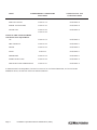
TOPIC UNDERWRITERS LABORATORY NATIONAL FUEL GAS
DOCUMENT CODE DOCUMENT
EXHAUST HOODS ANSI/UL 710 ANSI/NFPA 96
POWER VENTILATORS ANSI/UL 705 ANSI/NFPA 96
FILTER UNIT ANSI/UL 586 ANSI/NFPA 96
ANSI/UL 900
TYPES OF FIRE EXTINGUISHERS
AND DETECTION EQUIPMENT
CO
2 ANSI/UL 154 ANSI/NFPA 12
DRY CHEMICAL ANSI/UL 299 ANSI/NFPA 17
WATER ANSI/UL 626 ANSI/NFPA 13
FOAM ANSI/UL 8 ANSI/NFPA 11
SPRINKLERS ANSI/UL 199 ANSI/NFPA 13
SMOKE DETECTORS ANSI/UL 268 ANSI/NFPA 72
FIRE DETECTION THERMOSTATS ANSI/UL 521 ANSI/NFPA 72
IF MAINTENANCE IS REQUIRED, CONTACT YOUR LOCAL FACTORY SERVICER, LOCAL FACTORY
EPRESENTATIVE, OR THE FACTORY TO OBTAIN SERVICE.

Installation & Operations Manual 1189468 Rev 0 (03/07) Page 9
FILTER PROCEDURES
NOTE
When working with hot oil ALWAYS wear oil-proof, insulated gloves.
WARNING
NEVER • Run the filter system without a filter bag/paper.
NEVER • Empty the oil from the fryer before turning OFF the fryer burners.
NEVER • Store the UFM Filter Unit anywhere other than in the fryer filter cavity.
a. Slide the filter pan out. Carefully remove filtered residue off the filter media. Examine the filter media for
clogged or torn areas. Refer to filter media replacement instructions following this section. Reinstall the pan.
b. Turn the fryer that is to be filtered OFF (See Standby Shutdown). Remove the baskets from the fryer tank(s).
Use the clean out brush to lift out the tube screens. If there are excess crumbs in the fryer tank, remove them
with the crumb scoop.
c. If you have replaced the filter media or remove crumbs and debris, sprinkle Precoat Filter Aid on the filter
paper.
d. Check the drain spout to ensure that it is in the drain tower and over the filter pan opening.
e. Slowly open the green handled drain valve for the tank being filtered. If necessary use the clean-brush to clear
the crumbs from the drain. Use the brush to clean the sides of the tank as the oil drains.
WARNING
This filter pan is only large enough to hold the contents
of one (1) tank at once, during the filter process.
f. When the tank is empty, close the green handled drain valve. Open the red handled return valve to the tank
you are filtering. This will start the pump and return the oil to the bottom of the fry tank.
g. When bubbles are seen coming out of the oil return spout, close the red handled valve to turn the pump off. If
necessary add more oil to the tank to return the oil level to the fill mark. The fryer is now ready for use.
DRAINING A TANK
The filter system is also used to drain the fryers. You will need a container capable of holding 400°F oil and protective
gloves.
a. Rotate the drain down spout so that it extends in the container that you want to drain the shortening into.
b. Open the green handled drain valve for the tank to be drained. The oil will drain into the container you have
shosen. When the container is full or the fry tank is empty, close the green handled drain valve. If the
container was full repeat this step until fryer tank is empty.
c. Once tank is completely empty add new shortenning and follow fryer start up procedures.

Page 10 Installation & Operations Manual 1189468 Rev 0 (03/07)
WARNING
The power supply must be disconnected before servicing or cleaning the
appliance.
FILTER MEDIA REPLACEMENT
The filter module stores neatly under the fryer when not in use. The unit is very easy to use and allows for quick installation and
filtration, even under the busiest conditions. Follow the procedures below to change the filter media.
WARNING
At operating temperature, the shortening in the fryer may be hotter than
375°F (190°C). This hot, melted shortening will cause severe burns. Do not let
the hot shortening touch your skin or clothing. Always wear insulated oilproof
gloves when working on the filter system. It will be easier and safer if the filter
assembly has cooled to room temperature before handling any filter parts.
a. With the filter pan empty of oil, remove the filter media by grasping the filter pan handle and gently pull the
assembly toward the front of the fryer.
b. Separate the filter pickup tube from the filter pickup screen assembly by pulling up on the pickup tube just
above where it connects to the pickup screen assembly. Lift pickup tube and swing it to the left, until it rests
on the left hand side of the filter pan.
c. Grab filter screen pickup assembly lift handles and carry it to a trash barrel and shake off heavy discard any
debris that may be built upon the top of the assembly.
d. Unscrew the filter paper clip bracket from the filter paper support screen and slide the filter paper support
screen out of the filter paper clip bracket.
e. Remove filter paper support screen from the filter envelope.
f. All of the filter pick up assembly parts can be washed in a dish washer or a pot sink. Flush out the suction tube
assembly with hot water. After cleaning, it is very important to thoroughly dry the parts before reassembling.
Water and oil do not mix. Water in hot oil will cause the oil to splatter.
g. Start reassembling the filter pick up assembly by sliding the new filter paper on to the filter paper support
rack. Ensure that the hole in the filter paper goes over the pick up tube assembly threaded connector.
h. Fold the open end of the bag in two folds. The first fold should be approximately 1 inch from the end and the
second should be over the edge of the rack assembly.
i. Slide the clip screen over the folded end of the filter paper. Ensure the opening of the clip screen goes over the
pick up tube connection. Screw the suction tube connection onto the threaded connection.
j. Place the filter pickup assembly into the filter pan and slide the filter pan assembly back into the fryer cabinet.
k. Filter unit is now ready for use.

Installation & Operations Manual 1189468 Rev 0 (03/07) Page 11
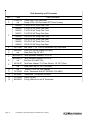
Parts Lists

Page 12 Installation & Operations Manual 1189468 Rev 0 (03/07)
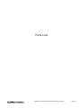
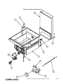
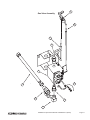
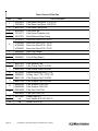
Tank Assembly and Thermostat
Item Part# Parts Description
1 A1406702 Clamp High Limit/Thermostat
2 n/a Screw 10-24 x 5/8 Pan Head SST Thred Forming
3
1188545 P16-PF45 36" Deeo Flue Front
1188546 P16-PF45 36" Deep Flue Rear
1188556 P16-PF45 42" Deep Flue Front
1188557 P16-PF45 42" Deep Flue Rear
1188585 P20-PF65 36" Deep Flue Front
1188583 P20-PF65 36" Deep Flue Rear
1188586 P20-PF65 48" Deep Flue Front
1188584 P20-PF65 48" Deep Flue Rear
4 60131002 Ball Valve, 1-1/4" Full Port Reversible Lug, Right Hand
5 A8030407 Drain Line Piping Adapter (non-filter)
6 n/a Steel Tank Plug 1/4" NPT
7
B3322501-C Tank Weldment Modular P16-PF45
B3322801-C Tank Weldment Modular P20-PF65
8 n/a Nut Hex 10-24 KEP Zinc
9
60130101 Tank Rear Adaptor 37.5 Flare Swivel x 1/2" NPT (filter)
n/a Steel Tank Plug 1/2" NPT (non-filter)
10 n/a Screw 10-24 x 3/4" Self Tapping
11 PP10539 Knob, Thermostat With Off, 200-400F (100-200C)
12 60125401 Thermostat , RX Millivolt 200-400F
13 PP10084 Switch, Hi-limit
14 B6744401 Wiring, Millivolt Hi-Limit & Thermostat

Installation & Operations Manual 1189468 Rev 0 (03/07) Page 13
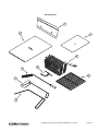
1
2
3
4
5
6
7
8
9
10
11
12
13
14
Tank Assembly and Thermostat

Page 14 Installation & Operations Manual 1189468 Rev 0 (03/07)
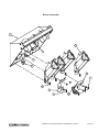
Burner Assembly
Item Part# Parts Description
1
B8039101 Burner Manifold Weldment P16-PF45
B8029801 Burner Manifold Weldment P20-PF65
2 60127501 Fitting Adaptor Flared 15/16-16 UN-2A x 1/2" FNPT BRASS
3 n/a Plug 1/8" NPT 3/16" Hex Socket Steel
4
P6071353 Orifice Tip, #53 - LP
P6071341 Orifice Tip, #41 - NAT
5
B8037302-C Burner, Slotted Face LP Gas
B8037301-C Burner, Slotted Face NAT Gas
6 n/a Screw 10-24 x 3/8" Self Tapping
7 A7020301 Filter Return Handle Bracket
8 A7020501 Filter Return Handle Cover
9
60128801 Natural Gas Standing Pilot
60128802 Propane Gas Standing Pilot
10 A8035302 Pilot Bracket
11 n/a Screw 10-24 x 1/4" Hex Head SST

Installation & Operations Manual 1189468 Rev 0 (03/07) Page 15
1
4
3
2
5
6
7
8
9
10
11
Burner Assembly

Page 16 Installation & Operations Manual 1189468 Rev 0 (03/07)
Gas Valve Assembly
Item Part# Parts Description
1 60128015 Tubing, Flexible With Fittings, 22 Gas
2 60128101 Valve, Gas Supply, Shut-Off
3 60127401 Fitting, Elbow Male Flare X MPT
4 60127601 Fitting, Adapter Female Swivel X 1/2 MPT
5
60126502 Conversion Kit, NAT to LP VR820
60126501 Conversion Kit LP to NAT VR820
6
60125201-C Millivolt Gas Valve, VS820 NAT
60125202-C Millivolt Gas Valve, VS820 LP
7 60119001 Tubing, Flexible Without Fittings 18 x 1/4 OD
8 60125501 Thermopile, Millivolt
9
60128801 Pilot Assembly, NAT
60128802 Pilot Assembly, LP

Installation & Operations Manual 1189468 Rev 0 (03/07) Page 17
1
2
3
4
5
6
4
7
8
9
Gas Valve Assembly

Page 18 Installation & Operations Manual 1189468 Rev 0 (03/07)
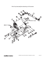
Filter Pump Assembly
Item Part# Parts Description
1 60132201 Teflon Hose 3/4" NPT Female Swivel x 3/4 MPT
2 B6677001 Filter Inlet Coupling
3 60131307 Nipple 3/4 NPT x 12 Black Iron
4 A7029201-C Filter Pump Mounting PLate
5A
60143501 Pump Assembly 8GPM .3hp 115/230V (50/60hz)
60143503 Pump Assembly 8GPM .3hp 208/240V (50/60hz)
60143505 Pump Motor Only 8GPM .3hp 115/230V (50/60hz)
60143506 Pump Motor Only 8GPM .3hp 115/230V (50/60hz)
60143507 Pump Head Only 8GPM (NO MOTOR)
6 n/a Washer 5/16 Flat
7 n/a Nut Hex 5/16 - 18 (KEP)
8 n/a Bolt 5/16 x 3/4
9 PP11338 Powert Cord Male IEC-320 16-3 AWG
10 n/a Elbow Black Iron 90
0
3/4NPT
11 n/a Nipple 3/4NPT x 2 Black Iron
12 n/a Street Elbow Black Iron 90
0
3/4NPT
13
60133503 Heater Tape 50W 120V 1/2 x 72
60133504 Heater Tape 50W 240/220V 1/2 x 72
60133508 Heater Tape 50W 208V 1/2 x 72
14 A7092201-C Filter Piping Clamp
15 n/a Screw 10-24 x 3/8" Self Tapping
16 A8033801 Elbow Female x Male 15/16 Flare

Installation & Operations Manual 1189468 Rev 0 (03/07) Page 19
Filter Pump AssemblyTank Assembly and Thermostat

Page 20 Installation & Operations Manual 1189468 Rev 0 (03/07)
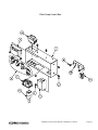
Filter Pump Contol Box
Item Part# Parts Description
1 A7028701-C Filter Pump Box Housing
2 B6748701 Filter Pump Box Wiring
3 60148401 Power Inlet/Outler IEC-320
4 n/a Nut 10-24 (KEP)
5
PP11058 Relay SPST 30A 24VAC (115V)
60104701 Relay DPST 30A 24VAC (208/220/240V)
6 n/a Screw 10-24 x 3/8
7
60130301 Transformer 5VA 120V
60130302 Transformer 5VA 240V
30130303 Transformer 5VA 208V
8
60077901 Circuit Breaker, SPST 250V 10A (115V)
60078502 Circuit Breaker, DPST 250V 5A (208/220/240V)
9
60128403 M-F Jumper Cord IEC-320 16-3 AWG x 34"
60128501 Cord NEMA 5-15P IEC-320 16-3 AWG x 96"
10 A1844001-C Cable Retainer
11 60130501 Lay In Strain Relief
Page is loading ...
Page is loading ...
Page is loading ...
Page is loading ...
Page is loading ...
Page is loading ...
Page is loading ...
Page is loading ...
-
 1
1
-
 2
2
-
 3
3
-
 4
4
-
 5
5
-
 6
6
-
 7
7
-
 8
8
-
 9
9
-
 10
10
-
 11
11
-
 12
12
-
 13
13
-
 14
14
-
 15
15
-
 16
16
-
 17
17
-
 18
18
-
 19
19
-
 20
20
-
 21
21
-
 22
22
-
 23
23
-
 24
24
-
 25
25
-
 26
26
-
 27
27
-
 28
28


Southbend P16 -PF45 Operating instructions
- Category
- Deep fryers
- Type
- Operating instructions
Ask a question and I''ll find the answer in the document
Finding information in a document is now easier with AI
Related papers


Other documents
-
Magikitchn 40S User manual
-
-
Pitco Frialator 65C+, 150K BTU User manual
-
-
 Keating Of Chicago SERIES 2000 User manual
-
 Keating Of Chicago SERIES 2000 User manual
-
Pitco 35C+, 90K BTU User manual
-
Pitco Frialator SGF User manual
-
Pitco Frialator SGF Operating instructions
-

