Product Category
68-633-50 Rev. A
03 11
CAUTION: Installation and service must be performed by authorized
personnel only. These units must be installed in accordance
with national and local electrical codes.
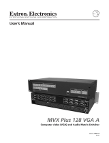
To install the VSC 500/700/700D, follow these steps. For detailed instructions
see the VSC 500/700/700D User Guide.
Step 1
Disconnect all power from the VSC and any input or output devices.
If the scan converter is to be set on top of a table top or other furniture,
install the self-adhesive feet on the bottom corners of the VSC. If the VSC
is to be rack mounted, mount the scan converter in a rack (see “Mounting
the VSC” in the VSC 500/700/700D User Guide).
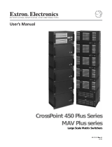
Step 2
Attach an input device and a loop-through device to the rear panel
of the VSC 500.
RGB input (VGA) connector
Buffered loop-through (VGA) connector
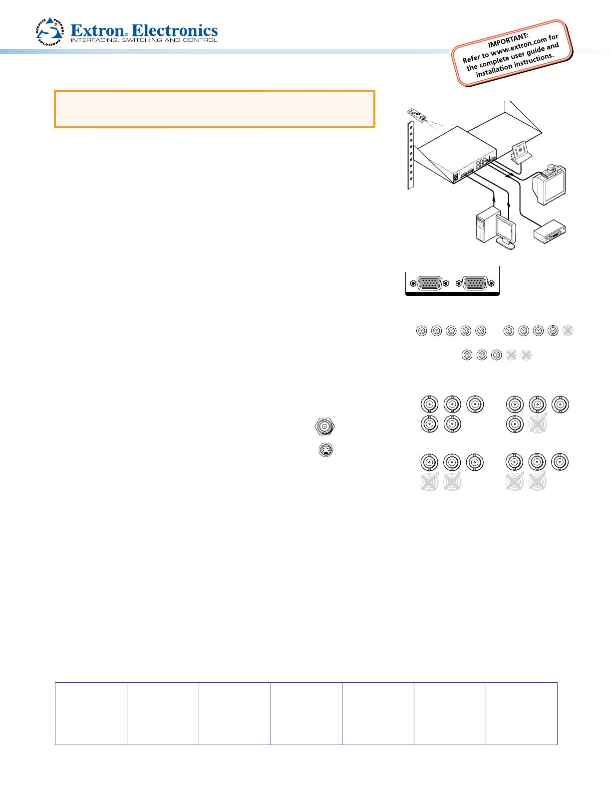
Attach an input device and a loop-through device to the
RGBHV
RGBS
R
GB
V
H/HV
R
GB
V
H/HV
VSC 700
VSC 700D
RGsB
R
G
B
H/HV
V
rear panel of the VSC 700/700D.
RGB input connectors and buffered loop-through connectors
Step 3
Attach an RGB or component video output device to the rear panel BNC connectors.
Step 4
Attach an S-video device to the S-video mini DIN connector
and an SDI device (700D only) to the SDI BNC connector.
Step 5
Plug the VSC, and input and output devices into a grounded AC source,
and turn on the input and output devices.
Step 6
Use the LCD menu screens or RS-232 programming to configure the VSC (in the VSC 500/700/700D User Guide, see the
“Installation and Operation” and the “RS-232 Programmer’s Guide” sections).
Step 7
Use the front panel Adjust horizontal ([) and Adjust vertical ({) adjustment knobs to center the image, then press the Size
button and rotate the knobs to fill the display screen (see “Front Panel Features” in the VSC 500/700/700D User Guide).
Step 8
Use the front panel Menu and Next buttons to navigate to the Filters menu. Using the front panel Adjust horizontal ([)
or Adjust vertical (
{) adjustment knobs, adjust the flicker level from the Flicker filter submenu and adjust the detail level
from the Horizontal filter submenu (see “Filters menu (Filters)” in the VSC 500/700/700D User Guide).
VSC 500/700/700D • Setup Guide
Videoconferencing
System
VCR
RS-232
Control
B/B-YG/YR/R-Y
RGB INPUT
BUFFERED
LOOP-THROUGH
VID
H
V
S-VIDEO
RS-232
/422
5
0
/6
0
H
z
1
0
0
-2
4
0
V
0
.3
A
O
U
T
P
U
T
S
IN
P
U
T
S
Extron
VSC 500
Scan Converter
PC
VSC Remote
Infrared Remote
Extron USA - West
Headquarters
+800.633.9876
Inside USA/Canada Only
+1.714.491.1500
+1.714.491.1517 FAX
Extron USA - East
+800.633.9876
Inside USA/Canada Only
+1.919.863.1794
+1.919.863.1797 FAX
Extron Europe
+800.3987.6673
Inside Europe Only
+31.33.453.4040
+31.33.453.4050 FAX
Extron Asia
+800.7339.8766
Inside Asia Only
+65.6383.4400
+65.6383.4664 FAX
Extron Japan
+81.3.3511.7655
+81.3.3511.7656 FAX
Extron China
+400.883.1568
Inside China Only
+86.21.3760.1568
+86.21.3760.1566 FAX
Extron Middle East
+971.4.2991800
+971.4.2991880 FAX
© 2011 Extron Electronics All rights reserved. www.extron.com
RGBHV
B/B-YG/YR/R-Y
HV
OUTPUTS
RGBS
B/B-YG/YR/R-Y
H
OUTPUTS
B/B-YG/YR/R-Y
V
H
RGsB
V
B/B-YG/YR/R-Y
V
H
R-Y, Y, B-Y
SDI
S-VIDEO
RGB INPUT
BUFFERED
LOOP-THROUGH
INPUTS
VSC 500