McIntosh C2300 Owner's manual

Category
Audio amplifiers
Type
Owner's manual
McIntosh Laboratory, Inc. 2 Chambers Street Binghamton, New York 13903-2699 Phone: 607-723-3512 www.mcintoshlabs.com
C2300
Tube Preamplifier
Owner’s Manual
2
The lightning ash with arrowhead, within an equilateral
triangle, is intended to alert the user to the presence of
uninsulated “dangerous voltage” within the product’s en-
closure that may be of sufcient magnitude to constitute
a risk of electric shock to persons.
The exclamation point within an equilateral triangle is
intended to alert the user to the presence of important
operating and maintenance (servicing) instructions in the
literature accompanying the appliance.
WARNING - TO REDUCE RISK
OF FIRE OR ELECTRICAL
SHOCK, DO NOT EXPOSE
THIS EQUIPMENT TO RAIN OR
MOISTURE.
NO USER-SERVICEABLE PARTS
INSIDE. REFER SERVICING TO
QUALIFIED PERSONNEL.
To prevent the risk of electric
shock, do not remove cover or
back. No user-serviceable parts
inside.
1. Read these instructions.
2. Keep these instructions.
3. Heed all warnings.
4. Follow all instructions.
5. Do not use this apparatus near water.
6. Clean only with a dry cloth.
7. Do not block any ventilation openings. Install
in accordance with the manufacturers instruc-
tions.
8. Do not install near any heat sources such as
radiators, heat registers, stoves, or other appa-
ratus (including ampliers) that produce heat.
9. Do not defeat the safety purpose of the polar-
ized or grounding-type plug. A polarized plug
has two blades with one wider than the other.
A grounding type plug has two blades and a
third grounding prong. The wide blade or the
third prong are provided for your safety. If
the provided plug does not t into your outlet,
consult an electrician for replacement of the
obsolete outlet.
10. Protect the power cord from being walked on
or pinched particularly at plugs, convenience
receptacles, and the point where they exit
from the apparatus.
11. Only use attachments/accessories specied by
the manufacturer.
12. Use only with the cart, stand, tripod, bracket,
or table specied by the manu-
facturer, or sold with the appa-
ratus. When a cart is used, use
caution when moving the cart/
apparatus combination to avoid
injury from tip-over.
13. Unplug this apparatus during lightning storms
or when unused for long periods of time.
14. Refer all servicing to qualied service person-
nel. Servicing is required when the apparatus
has been damaged in any way, such as power-
supply cord or plug is damaged, liquid has
been spilled or objects have fallen into the
apparatus, the apparatus has been exposed to
rain or moisture, does not operate normally, or
has been dropped.
15. Do not expose this equipment to dripping or
splashing and ensure that no objects lled
with liquids, such as vases, are placed on the
equipment.
16. To completely disconnect this equipment from
the a.c. mains, disconnect the power supply
cord plug from the a.c. receptacle.
17. The mains plug of the power supply cord shall
remain readily operable.
18. Do not expose batteries to excessive heat such
as sunshine, re or the like.
19. Connect mains power supply cord only to a
mains socket outlet with a protective earthing
connection.
IMPORTANT SAFETY
INSTRUCTIONS!
PLEASE READ THEM BEFORE
OPERATING THIS EQUIPMENT.
3
Your decision to own this McIntosh C2300 Tube Pre-
amplifier ranks you at the very top among discrimi-
nating music listeners. You now have “The Best.” The
McIntosh dedication to “Quality,” is assurance that
you will receive many years of musical enjoyment
from this unit.
Please take a short time to read the information in
this manual. We want you to be as familiar as pos-
sible with all the features and functions of your new
McIntosh.
Copyright 2007, 2011 © by McIntosh Laboratory, Inc.
Table of Contents
Thank You
Please Take A Moment
Technical Assistance
If at any time you have questions about your McIntosh
product, contact your McIntosh Dealer who is familiar
with your McIntosh equipment and any other brands
that may be part of your system. If you or your Dealer
wish additional help concerning a suspected problem,
you can receive technical assistance for all McIntosh
products at:
McIntosh Laboratory, Inc.
2 Chambers Street
Binghamton, New York 13903
Phone: 607-723-3512
Fax: 607-724-0549
Customer Service
If it is determined that your McIntosh product is in
need of repair, you can return it to your Dealer. You
can also return it to the McIntosh Laboratory Service
Department. For assistance on factory repair return
procedure, contact the McIntosh Service Department
at:
McIntosh Laboratory, Inc.
2 Chambers Street
Binghamton, New York 13903
Phone: 607-723-3515
Fax: 607-723-1917
The serial number, purchase date and McIntosh Dealer
name are important to you for possible insurance
claim or future service. The spaces below have been
provided for you to record that information:
Serial Number: _______________________________
Purchase Date: _______________________________
Dealer Name: ________________________________
Safety Instructions ..................................................... 2
Thank You and Please Take a Moment ...................... 3
Technical Assistance and Customer Service ............. 3
Table of Contents ....................................................... 3
General Information .................................................. 4
Connector and Cable Information ............................. 4
Introduction ................................................................ 5
Performance Features ................................................ 5
Dimensions ................................................................ 6
Installation ................................................................. 7
Connections:
Rear Panel Connections .............................................. 8
(Separate Sheet) ..................................................Mc2A
Connecting Components ............................................. 9
Connection Diagrams
(Separate Sheets) .................. Mc1A, Mc1B and Mc2B
Front Panel:
Front Panel Displays, Controls, Push-buttons
and Jack ..................................................................... 10
Setup:
How to Operate the Setup Mode ...............................11
Default Settings..........................................................11
Firmware Version .......................................................11
Trim Level Adjustment ......................................... 11-12
Re-Title Inputs ........................................................... 12
Meter Illumination On/Off ....................................... 12
Display Brightness .................................................... 12
Power Control Triggers ............................................. 12
Accessory Power Control .......................................... 13
Tube LED .................................................................. 13
Passthru ..................................................................... 13
Remote Control:
Remote Control Push-buttons ................................... 14
How to Operate by Remote Control ......................... 15
Operation:
How to Operate the C2300 .................................. 16-19
Additional Information:
Technical Description .......................................... 20-21
Specifications ............................................................ 22
Packing Instruction ................................................... 23
4
1. The C2300 uses Vacuum Tubes for amplifying the
audio signal. The C2300 is designed to have only
qualified Service Personnel perform any part(s)
replacement including all the vacuum tubes.
2. For additional connection information, refer to the
owner’s manual(s) for any component(s) connected
to the C2300 Tube Preamplifier.
3. The Main AC Power going to the C2300 and any
other McIntosh Component(s) should not be applied
until all the system components are connected
together. Failure to do so could result in malfunc-
tioning of some or all of the systems normal opera-
tions. When the C2300 and other McIntosh Com-
ponents are in their Standby Power Off Mode, the
Microprocessors Circuitry inside each component
is active and communication is occurring between
them.
4. Up to two Sensors can be wired in parallel for Re-
mote Control of the C2300 from other rooms.
5. Balanced and Unbalanced Inputs and Outputs can
be mixed. For example, you may connect signal
sources to Unbalanced Inputs and send signals
from the Balanced Outputs. You can also use Bal-
anced and Unbalanced Outputs simultaneously,
connected to different Power Amplifiers.
6. The Remote Control Supplied with the C2300 Tube
Preamplifier is capable of operating other com-
ponents. For additional information go to www.
mcintoshlabs.com.
7. When discarding the unit, comply with
local rules or regulations. Batteries should
never be thrown away or incinerated but
disposed of in accordance with the local
regulations concerning battery disposal.
Power Control, Trigger, Pass-Thru and Data
Cable Part No. 170-202
Six foot, shielded 2 conductor, with 1/8 inch stereo
mini phone plugs on each end.
Data Port Connectors
The C50 Data Out Ports send Remote Control Signals
to Source Components. A 1/8
inch stereo mini phone plug is
used for connection.
General Information and Connector Information
Connector and Cable Information
XLR Connectors
Below is the Pin configuration for the XLR Balanced
Input and Output Connectors on the C2300. Refer to
the diagrams for connec-
tions:
PIN 1: Shield/Ground
PIN 2: + Output
PIN 3: - Output
Power Control and Trigger Connectors
The C2300 Power Control Out, Trigger and Pass-Thru
Output Jacks send Power On/
Off Signals (+5 volt/0 volt)
when connected to other
McIntosh Components. An
additional connection on the
Main Power Control Jack is
for controlling the illumination
of the Power Output Meters on
McIntosh Power Amplifiers.
A 1/8 inch stereo mini phone
plug is used for connection to
the Power Control, Trigger and
Pass-Thru Outputs on the C50.
Note: The Power Control, Trig-
ger, Pass-Thru and Data
Connecting Cable is avail-
able from the McIntosh
Parts Department:
Data
Signal
N/C
Data
Ground
PIN 2 PIN 1
PIN 3
PIN 1
PIN 2
PIN 3
General Information
8. For additional information on the C2300 and other
McIntosh Products please visit the McIntosh Web
Site at www.mcintoshlabs.com.
Trigger
Control
Ground
N/C
Power
Control
Meter
Illumination
Control
Ground
Main Output Jack
Power
Control
Ground
N/C
Output 1 and 2, ACC
Jacks
5
Introduction
Performance Features
Introduction and Performance Features
The McIntosh C2300 Tube Preamplifier is one of the
finest Tube Preamplifiers ever created. The versatile
Preamplifier provides connections for various input
sources and outputs to drive multiple Power Ampli-
fiers. The C2300 reproduction is sonically transparent
and absolutely accurate. The McIntosh Sound is “The
Sound of the Music Itself.
• Electromagentic Input Switching with Level Trim
Adjustment
Digital Logic integrated circuits drive Electromag-
netic Switches on all Inputs and operating functions
for reliable, noiseless, distortion free switching. All
eight Inputs on the C2300 can be matched in level, so
there are no abrupt changes in volume levels between
the different Inputs. There is also a Record Monitor
function for checking the progress of a recording.
• Moving Coil and Moving Magnet Phono Inputs
The C2300 contains two different precision Phono
Preamplifier Circuits. One for low output Moving Coil
Phono Cartridges with selectable resistance loading,
the other is for Moving Magnet Cartridges with select-
able capacitive loading. Both circuits use the latest
designs to provide the lowest possible noise and dis-
tortion. The RIAA Correction Equalization Circuitry
utilizies close tolerance resistors and capacitors for an
extremely flat frequency response.
• Balanced Inputs
The Balanced Inputs allow the connection of a source
component using long cable lengths without a loss in
sound quality.
• Precision Tracking Volume Control
Volume levels are controlled by a new Multi-Stage
Precision Digitally Controlled Attenuator System with
a tracking accuracy of 0.1dB.
• Variable Rate Volume and Balance Control Selec-
tion
The C2300 Tube Preamplifier’s Volume and Balance
Control Circuitry provides an ideal rate of change with
control rotation.
• Assignable Tone Controls with Bypass
The C2300 remembers the Bass and Treble Control
Settings or the Tone Circuitry Bypass Option for each
input.
• Alphanumeric Fluorescent Display
The Multifunction Front Panel Display indicates the
Source Selection, Volume and Balance Levels. Setup
Mode Selections and Adjustments are also displayed.
The display intensity is adjustable.
• Precision Parts
Only the finest precision 1% tolerance resistors are
used throughout.
• Low Distortion
Distortion levels of all types are less than 0.08%. Mu-
sic is amplified with total transparency and accuracy.
• Passthru Mode
The Automatic Passthru Mode allows the C2300 to
become part of a Multichannel Sound System for
DVD-Audio, SACD and Home Theater Movies.
• Output Switching
Front panel Output Push-buttons control two Switched
Outputs that allow sending signals to two separate
Power Amplifiers.
• Remote Control with External Sensor Input
The Remote Control provides control of the C2300
operating functions and any McIntosh Source Com-
ponents connected to it. Enjoy your McIntosh System
from other rooms in your home by connecting exter-
nal sensors.
• Power Control Output and Trigger Assignment
A Power Control connection for convenient Turn-On
of McIntosh Power Amplifiers, Source Components
and Accessories is included. Two of the Power Con-
trol Ouputs may be assigned to activate when a given
Input is selected.
• Special Power Supply
Fully regulated Power Supplies and a special R-Core
Power Transformer ensure stable noise free operation
even though the power line varies.
• Extruded Side Panels
The sides of the C2300 are extruded aluminum panels
with a bead blast textured surface and a black anod-
ized finish.
• Fiber Optic Solid State Front Panel Illumination
The even Illumination of the Front Panel is accom-
plished by the combination of custom designed Fiber
Optic Light Diffusers and extra long life Light Emit-
ting Diodes (LEDs). The glass Front Panel ensures the
pristine beauty of the C2300 will be retained for many
years.
6
Dimensions
Dimensions
The following dimensions can assist in determining
the best location for your C2300. There is additional
information on the next page pertaining to installing
the C2300 into cabinets.
Front View of the C2300
Rear View of the C2300
Side View of the C2300
17-1/2"
44.45cm
7 -5/8"
19.37cm
7 -1/8"
18.10cm
6-3/8"
16.19cm
13 -1/4"
33.66cm
17-1/8"
43.50cm
16-1/2"
41.91cm
3/16"
0.48cm
13/16"
2.06cm
6-9/16"
16.67cm
10-9/16"
26.83cm
14-1/2"
36.83cm
2"
5.08cm
1-15/16"
4.92cm
7
Installation
Installation
The C2300 can be placed upright on a table or shelf,
standing on its four feet. It also can be custom in-
stalled in a piece of furniture or cabinet of your
choice. The four feet may be removed from the bottom
of the C2300 when it is custom installed as outlined
below. The four feet together with the mounting
screws should be retained for possible future use if the
C2300 is removed from the custom installation and
used free standing. The required panel cutout, ventila-
tion cutout and unit dimensions are shown.
Always provide adequate ventilation for your
C2300. Cool operation ensures the longest possible
operating life for any electronic instrument. Do not
install the C2300 directly above a heat generating
component such as a high powered amplifier. If all
the components are installed in a single cabinet, a
quiet running ventilation fan can be a definite asset in
maintaining all the system components at the coolest
possible operating temperature.
A custom cabinet installation should provide the
following minimum spacing dimensions for cool
operation.
Allow at least 6 inches (15.24cm) above the top, 2
inches (5.08cm) below the bottom and 1 inch (2.54cm)
on each side of the Tube Preamplifier, so that airflow
is not obstructed. Allow 19-1/2 inches (49.53cm) depth
behind the front panel. Allow 1-1/8 inch (2.9cm) in
front of the mounting panel for knob clearance. Be
sure to cut out a ventilation hole in the mounting shelf
according to the dimensions in the drawing.
6-9/16"
16.67cm
17-3/16"
43.66cm
Cutout Opening for Custom Mounting
C2300 Front Panel
Custom Cabinet Cutout
15"
38.1cm
7-1/2"
19.05cm
15"
38.10cm
Cutout
Opening
for
Ventilation
Cutout Opening for Ventilation
Support
Shelf
Chassis
Spacers
C2300 Side View
in Custom Cabinet
C2300 Bottom View
in Custom Cabinet
4"
10.16cm
12-5/16"
31.27cm
Cabinet
Front
Panel
6"
15.24cm
Opening
for Ventilation
Note: Center the cutout Horizontally
on the unit. For purposes of
clarity, the above illustration
is not drawn to scale.
1-1/16"
2.70cm
8
Rear Panel Connections
The identification of Rear Panel Connections for the
C2300 Audio Preamplifier is located on a separate
folded sheet contained in the Owner’s Manual Packet.
Refer to separate sheet “Mc2A” for the Rear Panel
Connections.
Rear Panel Connections
C2300 Tube Preamplifer Rear Panel
9
Connecting Components
The C2300 has the ability to automatically switch
power On/Off to McIntosh Source Components via the
Power Control connections. The Data Port Connec-
tions allow for the remote operation of basic functions
using the C2300 Remote Control. With an external
sensor connected to the C2300, remote control opera-
tion of the system is possible from another room and/
or when the C2300 is located in a cabinet with the
doors closed.
The connection instructions below, together with
the C2300 Input and Output Connection Diagrams
located on the separate folded sheets “Mc1A/1B and
Mc2A/2B, is an example of a typical audio system.
Your system may vary from this, however the actual
components would be connected in a similar manner.
For additional information refer to “Connector and
Cable Information” on page 4.
Power Control Connections:
1. Connect a Control Cable from the C2300 POWER
CONTROL ACC(C) Jack to the Power Control In
on the McIntosh SACD/CD Player.
2. Connect a Control Cable from the McIntosh
SACD/CD Player Power Control Out jack to the
McIntosh D/A Converter Power Control In Jack.
3. Connect a Control Cable from the McIntosh D/A
Converter Power Control Out jack to the McIntosh
Tuner Power Control In Jack.
4. Connect a Control Cable from the McIntosh Tuner
Power Control Out jack to the McIntosh Music
Server Power Control In Jack.
5. Connect a Control Cable from the C2300 POWER
CONTROL MAIN Out jack to the McIntosh Pow-
er Amplifier Left Channel Power Control In Jack.
Connect a Control Cable from the Left Channel
Power Amplifier Power Control Out to the Right
Channel Power Amplifier Power Control In Jack.
6. Optionally connect a Control Cable from the
C2300 POWER CONTROL OUTPUT 1 jack to
the McIntosh Power Amplifier (Secondary Room)
Power Control In Jack.
7. Connect any additional McIntosh Components in a
similar manner, as outlined in steps 1 thru 4.
Data Control Connections:
8. Connect a Control Cable from the C2300 TUNER
DATA PORTS Jack to the McIntosh TUNER1
Data In Jack.
9. Connect a Control Cable from the C2300 CD
DATA PORT Jack to the McIntosh SACD/CD
Player Data In jack.
10. Connect a Control Cable from the C2300 SRVR
DATA PORT Jack to the McIntosh Music Server
Data In jack.
11. Connect a Control Cable from the C2300 D/A
DATA PORT Jack to the McIntosh D/A Converter
Data In jack.
12. Connect any additional McIntosh Components in a
similar manner, as outlined in steps 8 thru 11.
Sensor Connections:
13. Connect a RG59U or RG6U Cable from the C2300
EXT SENSOR “F” Connector to the McIntosh
Sensor “F” Connector.
Audio Connections:
14. Connect an Audio Cable from the C2300 TUNER
INPUT Jacks to the McIntosh TUNER1 Fixed
Output Jacks.
15. Connect Balanced Cables from the C2300 CD
INPUT Jacks to the McIntosh SACD/CD Player
Fixed Balanced Output Jacks.
Note: Unbalanced Audio Cables may be used instead
of the Balanced Cables, but not both.
16. Connect an Audio Cable from the C2300 SRVR
INPUT Jacks to the McIntosh Music Server Out-
put Jacks.
17. Connect an Audio Cable from the C2300 SRVR
OUTPUT Jacks to the McIntosh Music Server
Input 3 Jacks.
18. Connect Balanced Cables from the C2300 D/A IN-
PUT Jacks to the McIntosh D/A Converter output
Jacks.
19. Connect the Audio Cables coming from the Turn-
table to the C2300 MC PHONO INPUT Jacks.
Note: If the Turntable has a Moving Magnet Car-
tridge connect the audio cables to the C2300
MM PHONO INPUT instead of the MC Input.
20. Connect Balanced Cables from the C2300 MAIN
OUTPUT jacks to the McIntosh Power Amplifiers
(Main Left and Right) Input jacks.
21. Connect an Audio Cable from the C2300 OUTPUT
1 jacks to the McIntosh Power Amplifier (Second-
ary) Input jacks.
22. Connect any additional McIntosh Components in a
similar manner, as outlined in steps 14 thru 21.
Optional “PassThru” Connections:
23. Connect Audio Cables or Balanced Cables from
the McIntosh MX Series A/V Control Center Front
Left and Right Channel Outputs to the CDR Input
Jacks.
24. Connect a Control Cable from the C2300
PASSTHRU to McIntosh MX Series A/V Control
Center Zone A Power Control Output.
Ground Connections:
25. Connect the Gound Cable coming from the Turn-
table to the C2300 GND Binding Post.
AC Power Cords Connections:
26. Connect the C2300 and any remaining compo-
nents’ AC Power Cords to a live AC outlet as
illustrated.
10
IR Sensor receives
commands from a
Remote Control
STANDBY/ON Push-button
switches the C2300 ON or
OFF (Standby) and resets the
microprocessors
VOLUME Control ad-
justs the listening level
for both channels
Connection for low im-
pedance dynamic head-
phones with 1/4” (0.64cm)
stereo phone type plug,
for private listening
MUTE Push-button
with indicator,
activates different
Muting Modes
MONO with in-
dicator, combines
the Left and Right
Channel signals for
Monophonic Sound
INPUT Control selects
the desired audio signals
for listening and record-
ing. It is also used in the
setup mode for various
functions
TONE BYPASS with
indicator, when activated
the audio signal bypass-
es the Tone Controls
SETUP Mode Push-button
with indicator, allows the
changing of the default
settings for Inputs, Levels,
Special Functions and the
Display
REC MONITOR Push-but-
ton with indicator, allows
listening to the playback of
REC/SRVR Source while
the recording is in process
DISPLAY indicates the Sources, Volume,
other Audio Settings, Operational Func-
tions and Setup Mode Settings
OUTPUTS 1 and 2 Push-buttons
with indicators, allow the C2300
to switch Power Control and Au-
dio to two separate Stereo Power
Amplifiers
METER indicates
the Preamplifier’s
Left Channel relative
Output Level
TRIM SELECT allows selection
of various types of audio settings.
It is also used in the setup mode
for various functions
TRIM ADJUST allows
adjustment of various types
audio settings. It is also
used in the setup mode for
various functions
METER indicates the
Preamplifier’s Right
Channel relative Output
Level
Front Panel Displays, Controls, Push-buttons and Jack
11
Setup
Your McIntosh C2300 has been factory configured for
default operating settings that will allow immediate
enjoyment of superb audio without the need for fur-
ther adjustments. If you wish to make changes to the
factory default settings, a Setup Feature is provided to
customize the operating settings using the Front Panel
Alphanumeric Display. Refer to the C2300 Front Panel
Illustration on the previous page while performing the
following steps.
Note: If the C2300 is currently On, proceed to step 2.
1. Press the STANDBY/ON Push-button to switch
On the C2300. The title TUBE WARMUP will
appear on the Front Panel Alphanumeric Display.
Refer to figure 1.
Note: The Red LED above the STANDBY/ON Push-
button lights to indicates the C2300 is con-
nected to AC Power.
2. Press the C2300 Front Panel SETUP Push-button.
The LED above the SETUP Push-button will il-
luminate and the Front Panel Display will indicate
C2300 V1.00 or higher. Refer to figure 2.
Note: The Front Panel Display will indicate C2300
V1.00 or higher the first time, after that it will
display whatever Setup Mode was last ac-
cessed.
3. Rotate the MENU (INPUT) Control and notice the
Setup Mode goes forward through eight different
possible adjustment selections and one informa-
tional display.
How to Operate the Setup Modes
Figure 2
Figure 3
Figure 1
4. To exit from a specific Setup Mode, press the
SETUP Push-button a second time. The LED
above the SETUP Push-button will extinguish
and the Front Panel Display will revert back to its
normal display. Refer to figure 3.
Default Settings
The Default Settings Chart below indicates the Func-
tion Name, Default Setting and the Page Number for
additional information.
Default Settings
Function Name Setting Page No.
C2300 V_._ _ 11
TRIM TUNer 0.0 11
INPUT
3 â TUN
12
METER ON 12
DISPLAY 7 12
TRIGger TUNER> - - 12
ACCessory <C> MAIN 13
TUBE LED ON 13
PASSTH RU OFF 13
The C2300 functionality is controlled by internal
software that is know as Firmware. The Version of the
Firmware in the C2300 can be identified at any time
by utilizing the Setup Mode.
1. Press the SETUP Push-button to access the Setup
Mode.
2. Rotate the MENU (INPUT) Control until C2300
V1.00 or higher appears. Refer to figure 2.
Firmware Version
3. The number after the character “V” is the Firm-
ware number.
4. Press the SETUP Push-button to exit the Setup
Mode.
Source Components can have slightly different volume
levels resulting in the need to readjust the C2300
Volume Control when switching between different
sources. The C2300 allows the adjustment of levels for
each of the Source Inputs for the same relative volume.
The Tuner and CD Inputs are used in the following
example.
Note: The range of adjustment is ± 6dB. The Tape/Re-
cord Output Levels are unaffected by any changes
in the Level Trim Settings. The Trim adjustments
made are retained in permanent memory. They
can be changed by performing a new Trim Proce-
dure. The Tuner Input Volume Level can serve as
a reference or choose another source frequently
listened to. The reference Input Source should be
set to a Trim Level of 00.
1. Rotate the INPUT Control to select the Tuner
Input and adjust the VOLUME Control to the
desired listening level.
2. Press the SETUP Push-button to access the Setup
Mode.
3. Rotate the MENU (INPUT) Control until “TRIM
TUN 0.0” appears on the Front Panel Alphanu-
meric Display. Refer to figure 4.
Note: If necessary, rotate the SELECT 1 (TRIM
SELECT) Control for “TUN” and rotate the
SELECT 2 (TRIM ADJUST) for ”0.0”.
Trim Level Adjustment
Figure 4
12
4. Rotate the SELECT 1 Control or use the Remote
Control ◄INPUT► push-button until the display
indicates “TRIM CD 0.0”.
5. Rotate the SELECT 2 Control or use the Remote
Control LEVEL q or p Push-buttons until Lis-
tening Volume Level of the CD Input is the same
as the Tuner Volume Level. The figure 5 illustra-
tion indicates a -2.5dB decrease in the CD Level.
6. Rotate the SELECT 1 Control until the name of
the next Input to be adjusted is displayed.
7. Repeat steps 5 and 6 until all the Inputs with
sources connected to the C2300 have the same
relative volume levels when switching between
them. Record any changes made to the various in-
puts from the default settings in the “Input Source
Settings” chart below.
8. Press the SETUP Push-button to exit the Setup
Mode.
Input Source Settings
Default Title New Title Trim Trigger
TUNER
DVD
D/A
CD
CDR
SERVER
MC PHONO
MM PHONO
Figure 5
Re-Title Inputs
The C2300 provides the ability to change the default
Input Titles to match the components in your system.
In the following example the CDR Input will be re-
named and appear as AUX on the Front Panel Alpha-
numeric Display.
Notes: 1. One of the high level Inputs may be renamed
to AUX or swiched Off. If any input is switched
Off its name will no longer appear on the Front
Panel Alphanumeric Display when using the
INPUT Control, nor is it accessible with the
Remote Control.
2. When a high level input is switched Off its name
will become available to the remaining high
level inputs.
3. The Phono MC and Phono MM Inputs are
designed for connection of a turntable only and
thus the title is not changeable. However, the
Phono Input may be switched Off.
1. Press the SETUP Push-button to access the Setup
Mode.
2. Rotate the MENU Control until “INPUT 3
âTUN” appears on the Front Panel Alphanumeric
Display.
3. Rotate the SELECT 1 Control until “INPUT 7
âCDR” appears on the Front Panel Alphanumeric
Display. Refer to figure 6.
4. Rotate the SELECT 2 Control until the Front
Panel Alphanumeric Display indicates “INPUT 7
AUX”. Refer to figure 7.
5. Press the SETUP Push-button to exit the Setup
Mode.
Meter Illumination On/Off
The Front Panel Meter Illumination may be switched
On or Off. Follow the steps below to switch the Meter
Illumination Off.
1. Press the SETUP Push-button to access the Setup
Mode.
2. Rotate the MENU Control until the words ME-
TER ON appears.
3. Rotate the SELECT 2 Control until the Front
Panel Alphanumeric Display indicates “METER
OFF”.
4. Press the SETUP Push-button to exit the Setup
Mode.
Figure 6
Figure 7
Power Control Triggers
The OUTPUT 1(A) and OUTPUT 2(B) Power Control
Outputs are reassignable to activate only when a given
Input is selected. In the following example, the Power
Control OUTPUT 1(A) Jack will be set to function as
TRIGGER A for the DVD Input.
1. Press the SETUP Push-button to access the Setup
Mode.
Display Brightness
The Front Panel Alphanumeric DISPLAY Brightness
may be varied from a setting of 1 (Dim) to 7 (Bright).
Follow the steps below for reducing the Display
Brightness.
1. Press the SETUP Push-button to access the Setup
Mode.
2. Rotate the MENU Control until the word DIS-
PLAY 7 appears.
3. Rotate the SELECT 2 Control until the Front Panel
Alphanumeric Display indicates “Display 3.
4. Press the SETUP Push-button to exit the Setup
Mode.
Trim Level Adjustment, con’t
13
The C2300 can be part of a Multichannel Sound Sys-
tem for SACD, DVD-Audio and Home Theater. The
Right and Left Front Channels from a McIntosh A/V
Control Center or Surround Decoder can “Passthru”
the C2300 and onto its associated Power Amplifier(s).
The Setup Mode allows the activation of the Passthru
Mode and the Selection of the C2300 Input (Input
numbers 3 - 8 on the Rear Panel) that will be used for
the Right and Left Front Channels. In the example
below, the Right and Left Front Channels from the
Multichannel Processor/Decoder will be connected to
the CDR (7) Input Jacks on the C2300. Refer to page 9
for additional connection information.
1. Press the SETUP Push-button to access the Setup
Mode.
2. Rotate the MENU Control until “PASSTHRU
OFF” appears on the Front Panel Alphanumeric
Display.
2. Rotate the MENU Control until “TRIG TUNER
> - - ” appears on the Front Panel Alphanumeric
Display. Refer to figure 8.
3. Rotate the SELECT 1 Control until the display
indicates “TRIG DVD > - - ”.
4. Rotate the SELECT 2 Control until the display
indicates “TRIG DVD > A ”. Refer to figure 9.
5. Press the SETUP Push-button to exit the Setup
Mode.
Setup, con’t
Figure 9
Figure 8
Accessory Power Control
The ACC (C) Power Control Output is reassignable
from the default setting of going ON/OFF with the
C2300 (Main), to being controlled by the Remote
Control ACC ON/OFF Push-buttons. To reassign it
perform the following:
1. Press the SETUP Push-button to access the Setup
Mode.
2. Rotate the MENU Control until “ACC < C >
MAIN” appears on the Front Panel Alphanumeric
Display.
3. Rotate the SELECT 2 Control until the display
indicates “ACC< C > ON”. Refer to figure 10.
4. Press the SETUP Push-button to exit the Setup
Mode.
Tube LED
To swich Off the Tube LED green illumination per-
form the following:
1. Press the SETUP Push-button to access the Setup
Mode.
2. Rotate the MENU Control until “TUBE LED ON”
appears on the Front Panel Alphanumeric Display.
3. Rotate the SELECT 2 Control until the display
indicates “TUBE LED OFF.
4. Press the SETUP Push-button to exit the Setup
Mode.
Figure 10
Passthru
Figure 11
3. Rotate the SELECT 2 Control until the display
indicates “PASSTHRU 7 ”. Refer to figure 11.
4. Press the SETUP Push-button to exit the Setup
Mode.
14
Remote Control Push-Buttons
Note: Push-buttons whose function is not identified above are for use with other McIntosh Products.
Press TRIM and then the LEVEL
Push-buttons to select and adjust
various functions
Press to listen to the selected
Record Out Signal
Scrolls through the available
C2300 Inputs
Displays On Screen Functions on the
McIntosh Music Server and a variety
of other McIntosh Components
Press to Power the C2300 ON
Selects one of nine available
Audio Sources
Selects a Disc Player, Music Server
or Recorder Function. Seek Sta-
tions Up or Down the AM/FM Dial.
Select AM/FM Station Presets and
performs various functions on a
variety of McIntosh Components
Use to select tuner presets, disc
tracks or any numbered operation
Mutes the audio
Adjusts the volume level
up or down
Selects On Screen Functions on a
variety of McIntosh Components
Selects AM Tuner Operating
Functions and Disc Selection on
certain McIntosh Disc Players
Selects FM Tuner Operating
Functions and Track Selection on
certain McIntosh CD Players
Press to review Tuner Station
Presets with an external McIntosh
Tuner connected and select certain
functions on a variety of McIntosh
Components
Press MODE to switch between
Stereo and Mono Modes
Turns AC Power ON or OFF to
McIntosh Components when con-
nected to ACC Power Control Jack,
refer to “How to use the Remote
Control” Acc On/Off information
LED illuminates during the time a
remote command is sent to the C2300
Selects Functions as a “shift” key
when used with the AM or FM
push-buttons to select Output 1
or 2
Press to Power the C2300 OFF
Use to select tuner presets, disc
tracks or any numbered operation
Scrolls through the
available C2300 Inputs
15
How to use the Remote Control
The supplied HR073 Remote Control is capable of
directly controlling the functions of contemporary
McIntosh Source Components connected to the C2300
via the Data Ports.
Note: If at any time the C2300 seems unresponsive to
HR073 Remote Control Commands press the
Push-button first.
Input Source Selection
Press the appropriate Source Push-button to select the
desired program source. Sources may also be selected
by pressing the ◄INPUT► push-button.
Mute
Press the MUTE Push-button to mute audio. The
Record Signals present at the SRVR REC OUTPUT
Jacks are not affected by the MUTE function. The
C2300 Front Panel Alphanumeric Display will indi-
cate the word MUTE.
Note: For additional information on the various Mute
Modes refer to page 18.
Mode
Press the MODE Push-button to switch from Stereo to
Mono for Monophonic listening.
Disc, Server and Tape Functions
Use these push-buttons to operate a DVD Player, CD
Player, CD Changer, Music Server or Recorder.
Numbered Push-buttons
Press Push-buttons 0 through 9 to access tuner sta-
tion presets, tracks on discs or selections on a Music
Server.
Disc and Track
Use the AM(disc)and FM(track)Push-buttons when a
Disc Player or Music Server is being used.
Tuner Push-buttons
Press the AM or FM Push-button to select the de-
sired broadcast band. Press and release the Seek7 or
Seek8 Push-button to seek the next available station.
Press and hold a Seek7 or Seek8 Push-button to seek
continuously from station to station.
Volume
Press the VOLume + or - Push-button to raise or lower
the listening volume level.
Note: The Record Signals present at REC OUTPUTS are
not affected by volume changes.
Pause
Press the Pause Pushbutton to perform various func-
tions on a variety of McIntosh Components. It will
also pause the playing of a disc or tape player.
Trim
Press the TRIM Push-button until the word “BAL-
ANCE __” appears on the Alphanumeric display,
then press the LEVEL + Push-button to emphasize the
Left Channel or LEVEL - Push-button to emphasize
the Right Channel.
Press the TRIM Push-button until the word “TRIM
_ _ _ _ _” appears on the Alphanumeric display, then
press the LEVEL + or - Push-button to match the vol-
ume level of the previously selected Input.
Note: For additional information on the other Trim Fuc-
tions refer to pages 16, 17 and 18.
Acc On/Off
Press ACC ON to turn the power ON or ACC OFF
switches AC Power OFF to McIntosh Components
when connected to the ACC Power Control Jack.
Amplifier Selection
Press the BLUE (Setup) Push-button followed by the
AM (Output 1) or FM (Output 2) Push-buttons, to con-
trol the rear panel OUTPUTS 1, 2 (ON or OFF). These
OUTPUTS provide signals to a Power Amplifier or
other accessory component.
16
Power On
The Red LED above the STANDBY/ON Push-button
lights to indicate the C2300 is connected to AC Power.
To Switch ON the C2300, press the STANDBY/ON
Push-button on the Front Panel or the on the Remote
Control either the PWR(Power) or (Power On)
Push-button. The title TUBE WARMUP will appear
on the Front Panel Alphanumeric Display after Turn-
On, with the Audio Outputs muted. Refer to figures
12, 13, 14 and 21.
Source Selection
Select the desired source using the INPUT Control or
Remote Control.
Volume Control
Rotate the Front Panel VOLUME Control or use the
VOLume + or - Push-buttons on the Remote Control
for the desired listening level.
Trim Functions
The C2300 has six different Trim Selections with Ad-
justments. The Trim Selections include Balance, Bass,
Treble, Tone Bypass, Input Level Matching and Meter
Illumination. The Trim Settings are stored in memory
independently for each Input Source Selected, the only
exception being Meter Illumination setting of On or
Off which is the same for all inputs.
BALANCE
Listening balance varies with different program sourc-
es, room acoustics and listening positions relative to
the Loudspeakers. Use the Balance (Trim Function) as
needed to achieve approximately equal listening vol-
How to Operate the C2300
ume levels in each Loudspeaker. To adjust the Balance
perform the following:
1. Rotate the Front Panel TRIM SELECT Control or
press the TRIM Push-button on the Remote Con-
trol until “BALANCE 00” appears on the Front
Panel Alphanumeric Display.
2. Rotate the TRIM ADJUST Control or press the
LEVEL + / - Push-buttons to emphasize the Left
Channel or the Right Channel. Refer to figure 15.
The Front Panel Display indicates the Balance changes
in steps from 0 to 107. After approximately 3 sec-
onds the Alphanumeric Display returns to indicate
the Source Selection and Volume Level. When the
Balance is set to favor either left or right channel, the
volume number indicated will have a “< or >” symbol
on either side of the number. Refer to figure 16. To
verify the Balance setting without changing it, use the
TRIM SELECT Control or TRIM Push-button and
select Balance.
BASS
The Intensity of the Low Frequencies in the music can
be increased or decreased by using the Trim Select
and Trim Adjust Controls. To make adjustment per-
form the following:
1. Rotate the Front Panel TRIM SELECT Control or
press the TRIM Push-button on the Remote Con-
trol until “BASS __” appears on the Front Panel
Alphanumeric Display.
Figure 14
Figure 13
Figure 12
Figure 15
Figure 16
17
2. Rotate the TRIM ADJUST Control or press the
LEVEL + / - Push-buttons to increase or decrease
the volume level of the low frequencies. Refer to
figure 17.
The Front Panel Display indicates the Bass changes in
steps from -12dB to (+)12dB. After approximately 3
seconds the Alphanumeric Display returns to indicate
the Source Selection and Volume Level.
TREBLE
The Intensity of the High Frequencies in the music can
be increased or decreased by using the Trim Select
and Trim Adjust Controls. To make adjustment per-
form the following:
1. Rotate the Front Panel TRIM SELECT Control
or press the TRIM Push-button on the Remote
Control until “TREBLE __” appears on the Front
Panel Alphanumeric Display.
2. Rotate the TRIM ADJUST Control or press the
LEVEL + / - Push-buttons to increase or decrease
the volume level of the high frequencies. Refer to
figure 18.
The Front Panel Display indicates the Treble changes
in steps from -12dB to (+)12dB. After approximately
3 seconds the Alphanumeric Display returns to the
indicate the Source Selection and Volume Level.
TONE ENABLE/BYPASS
With the Tone Bypass active, the Bass and Treble
Settings for the currently selected Input Source are
electronicaly bypassed. When the Tone Bypass is
switched Off the previous settings for Bass and Treble
will be restored. To activate Tone Bypass perform the
following:
1. Rotate the Front Panel TRIM SELECT Control or
press the TRIM Push-button on the Remote Con-
trol until “TONE BYPASS” appears on the Front
Panel Alphanumeric Display.
2. Rotate the TRIM ADJUST Control or press the
LEVEL + / - Push-buttons to activate the Tone
Bypass or deactivate the Tone Bypass. Refer to
figure 19.
After approximately 3 seconds the Alphanumeric
Display returns to indicate the Source Selection and
Volume Level.
TRIM LEVEL
The Trim Level adjustments allows for making fine
adjustments to the previously performed Trim Level
Adjustments in the Setup Section of this Owner’s
Manual on page 11. To make fine adjustment to the
currently selected Input Source perform the following:
1. Rotate the TRIM SELECT Control or press the
TRIM Push-button on the Remote Control until
“LEVEL _._” appears on the Front Panel Alpha-
numeric Display. Refer to figure 20.
2. Rotate the TRIM ADJUST Control or press the
LEVEL + / - Push-buttons to adjust the volume
level from -6dB to (+)6dB.
Refer to figure 20.
After approximately 3 seconds
the Alphanumeric Display re-
turns to the indicate the Source
Selection and Volume Level.
METER ILLUMINATION
The C2300 Front Panel Meter
Illumination may be switched
On or Off by performing the
following:
1. Rotate the TRIM SELECT
Control or press the TRIM
Push-button on the Remote
Control until “METER
ON” appears on the Front
Panel Alphanumeric Dis-
play.
2. Rotate the TRIM ADJUST
Control or press the LEVEL
+ / - Push-buttons to switch
On or Off the Meter Illumi-
nation.
After approximately 3 seconds
the Alphanumeric Display re-
turns to the indicate the Source
Selection and Volume Level.
Note: When the Main Power
Control of the C2300 is
connected to a McIntosh
Power Amplifier with Re-
mote Meter Illumination Control, the C2300 Meter
Illumination Setting of On or Off will also affect
the Power Amplifer Meter Illumination.
How to Operate the C2300
Figure 17
Figure 18
Figure 19
Figure 21
Figure 20
18
Mono
Press the Front Panel MONO Push-button or the
MODE Push-button on the Remote Control to com-
bine left and right stereo signals to a Monophonic Sig-
nal. The Front Panel LED will illuminate indicating
the MONO Mode is active. The C2300 automatically
stores into memory for each Input, the Selection of the
Stereo or Mono Mode.
Note: The signals at the SRVR OUT (REC) Jacks are
not affected.
Record Monitor
Press the REC MONITOR Push-button to hear the
SERVER Playback Signal during the recording pro-
cess.
Setup
Pressing the SETUP Push-button activates the Setup
Mode of the C2300 and allows customizing various
operating functions. Refer to page 11 for additional
information.
Mute
Press the MUTE Push-button, on the C2300 Front
Panel or on the Remote Control, to Mute the Audio at
the OUTPUTS Connectors and HEADPHONES Out-
put Jack. The Front Panel Alphanumeric Display will
indicate the Input Source Name followed by the word
MUTE in place of the actual volume setting. Refer to
figure 24.
PHONO ADJUSTMENTS
When the Phono MC or Phono MM Input is selected
an additional TRIM SELECT FUNCTION becomes
available for adjustment. Perform the following steps
to make the Phono Trim Adjustments:
1. Select either the Phono MM or Phono MC Input
using the INPUT Control.
2. Rotate the TRIM SELECT Control or press the
TRIM Push-button on the Remote Control until
“PHMM _ _ _ PF” or “PHMC _ _ _ OHM
appears on the Front Panel Alphanumeric Display.
Refer to figures 22 and 23.
3. Rotate the TRIM ADJUST Control or press the
LEVEL + / - Push-buttons to select from the
available values of cartridge loading (Ohms for a
Moving Coil Cartridge or Capacitance for a Mov-
ing Magnet Cartridge) that comes closest to the
Cartridge Makers recommended value.
After approximately 3 seconds the Alphanumeric
Display returns to the indicate the Source Selection
and Volume Level.
Tone Bypass
Press the TONE BYPASS Push-button to Bypass the
Tone Control Circuitry, thus providing a flat frequen-
cy response. If the AUTOTONE circuit is set to the
On position in Setup Mode, the C2300 will remember
for each input whether the Tone Bypass is active. The
Front Panel LED will illuminate indicating the BY-
PASS Mode is active.
How to Operate the C2300, con’t
Figure 24
Figure 22
Figure 23
Figure 14
19
Output Meters
The C2300s Output Meters indicate the Output
Voltage available at the MAIN and OUTPUT 1 & 2
Jacks to drive Power Amplifiers. Refer to figure 27.
The Meters are calibrated in dB (decibels) and respond
to all the peaks contained in the musical informa-
tion. They indicate to an accuracy of at least 95% of a
single cycle from a 2000Hz tone burst.
The Meter Electronic Circuitry “Time Stretches” the
Meter Drive Signal so the Meter Pointer pauses just
long enough for the human eye to see it and is fol-
lowed by a moderate decay rate.
How To Make A Recording
1. Select the Source Input Signal you wish to record.
2. Adjust the record level using the recorder volume
control and proceed with the recording process.
3. To listen to the playback of the program source
just recorded, press the RECord MONITOR Push-
button.
Note: The C2300 SRVR (REC) OUTPUTS are not af-
fected by the VOLUME or BALANCE controls.
Reset of Microprocessors
In the unlikely event the controls of the C2300 stop
functioning, the microprocessors can be reset by per-
forming the following:
Pressing the Mute Push-button a second time or
adjusting the volume control (either the Front Panel or
Remote Control) will un-mute the C2300.
If the Front Panel MUTE Push-button is pressed
for at least 3 seconds, the C2300 will mute the OUT-
PUTS connectors, yet listening with headphones will
continue until the Mute Push-button is pressed again
for 3 seconds. The Front Panel Alphanumeric Display
will indicate the Input Source Name, Volume Setting
and a Dot. Refer to figures 25 and 26.
Output 1 and 2
Press the Front Panel OUTPUT 1 / OUTPUT 2 Push-
button or use the Remote Control and press the 2nd
Push-button followed by the OUTPUT 1 / OUTPUT
2 Push-button to send audio to separate Power Am-
plifiers connected to the rear panel OUTPUTS 1 or
2 Jacks. It also activates the POWER CONTROL
OUTPUT 1 /OUTPUT 2 Jacks on the rear panel of the
C2300. To stop the Audio and Power Control Signals
from going to the separate Power Amplifiers, press the
same Push-button(s) a second time.
Headphones Jack
Connect a pair of dynamic headphones with a 1/4”
(0.635cm) stereo phone type plug to the Headphones
Jack for private listening.
How to Operate the C2300, con’t
Figure 26
Figure 27
Figure 25
1. Press and hold in the STANDBY/ON Push-button
for approximately five seconds and then release the
push-button.
2. Press the STANDBY/ON Push-button, the C2300
will resume normal operation.
Note: This can be performed with the C2300 On or in
the Standby Mode.
20
The McIntosh engineering staff has created a Tube
Preamplifier without compromise, using the most
advanced McIntosh circuit design concepts. Many
months of design, testing and measuring were re-
quired. Extensive controlled listening tests, the ulti-
mate form of measuring, were made before the final
design was accepted.
Silent Audio Switching
All signal switching in the C2300 is done by Electro-
Magnetic devices. Electro-Magnetic Switching is a
proven technology that uses the latest in materials
and manufacturing methods. Each switch consists of
a glass tube that is filled with an inert oxygen-free
atmosphere and sealed with tiny leads protruding
from either end. These leads extend into the tube and
overlap one another with a separation of a few thou-
sandths of an inch. The leads are made from a ferrous
material that is influenced by a magnetic field. They
are first plated with gold as a base material, then with
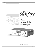
rhodium and finally ruthe-
nium. Ruthenium is the best
contact material known.
Refer to figure 28.
The glass assembly is then
placed in the center of a
multilayer coil of copper
wire. The entire assembly
is molded together in a tough shock absorbing mate-
rial. The switch and coil connectors extend from the
bottom in the form of printed circuit board terminals.
When a DC voltage is applied to the coil, current
flows and creates a magnetic field. The force of the
field causes the leads to bend and contact one another
inside the sealed glass tube. The inert gas eliminates
corrosion of the contacts and insures a low resistance,
distortion free switch.
All inputs, outputs, and data ports are controlled
by logic circuits in the C2300. The logic is changed
by Front Panel Push-buttons or by a microproces-
sor IR decoder. This microprocessor IR decoder is
programmed with exclusive McIntosh software. It
receives data from the Front Panel or Sensors and pro-
vides the command signals for input switching, data
switching, tone control and volume control.
Phono Circuitry
McIntosh has long been known for its expertise in low
noise discrete amplifier circuits. The MC Amplifier
consists of two stages, which together have a gain of
60dB at 1000Hz. The first stage (pre-preamplifier) is
a new design Moving Coil Preamplifier using special
ultra low noise circuitry with out the need for a step-
up transformer. It offers the ability to change the input
impedance from 25 ohms to 1000 ohms in six steps to
match a wide variety of Moving Coil Cartridges. The
C2300 utilizes a double filtered power supply design,
just for the Moving Coil Preamplifier.
The second (compensation) amplifier stage uses
12AX7A tubes. Its input stage has been optimized for
low noise and low distortion performance. With high
open loop gain, negative feedback is used around the
Phono Amplifier to further reduce noise, distortion
and has a very wide dynamic range. The feedback
network also provides precision RIAA frequency
compensation. The output is buffered by a unity gain
amplifier for low output impedance.
The MM Phono Amplifier uses 12AX7A tubes. Its
input stage has been optimized for low noise and low
distortion performance. It offers the ability to change
the load capacitance from 50 pF to 750 pF in 50 pF
steps to match a wide variety of Moving Magnet Car-
tridges. With high open loop gain, negative feedback
is used around the Phono Amplifier to further reduce
noise, distortion and has a very wide dynamic range.
The feedback network also provides precision RIAA
frequency compensation. The output is buffered by a
unity gain amplifier for low output impedance.
Tone Control Circuitry
A control attenuator inserts a series tuned circuit into
either the feedback or input section of the tone ampli-
fier. The level is set by a digitally controlled electronic
attenuator. This provides a 12dB boost or cut in 1dB
steps at the frequency of the tuned circuit. The Bass
turn-over frequency is 200Hz. The Treble turn-over
frequency is 2kHz. The overall gain of the stage is
0dB when the tone is adjusted to flat. The TONE
BYPASS switch removes all tone control circuits from
the signal path.
Volume Adjustments
The most frequently operated control on a Preampli-
fier is the Volume Control. So it is no surprise that
McIntosh has devoted a substantial amount of time in
pursuit of the “Perfect Volume Control System”.
Conventional Mechanical Controls have poor
tracking especially when it comes to maintaining
channel balance and after a period of time they tend
to introduce noise into the audio signal, as they are
rotated. The one desirable thing they have is the rate
of change in volume for degrees of rotation, known as
the audio taper. Using Electronic Circuitry for control-
ling, the volume can be designed to be free from noise
and maintain channel balance, however the audio
Technical Description
Figure 28
  • Page 1 1
  • Page 2 2
  • Page 3 3
  • Page 4 4
  • Page 5 5
  • Page 6 6
  • Page 7 7
  • Page 8 8
  • Page 9 9
  • Page 10 10
  • Page 11 11
  • Page 12 12
  • Page 13 13
  • Page 14 14
  • Page 15 15
  • Page 16 16
  • Page 17 17
  • Page 18 18
  • Page 19 19
  • Page 20 20
  • Page 21 21
  • Page 22 22
  • Page 23 23
  • Page 24 24

McIntosh C2300 Owner's manual

Category
Audio amplifiers
Type
Owner's manual

Ask a question and I''ll find the answer in the document

Finding information in a document is now easier with AI