
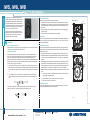
Aspire™ In-Wall Speakers
quickstart guide
IW5, IW6, IW8
www.crestron.com
888.273.7876 201.767.3400
Specifications subject to
change without notice.
IW5, IW6, IW8
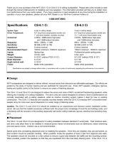
Mount/Remove Speakers
The in-wall speakers include six toggle clamps that simplify the mounting process. If the
grilles are mounted on the speakers, remove them before proceeding. (Refer to “Install/
Remove Grilles”, below.)
1. Connect the speaker cable wires to the spring terminals by pressing the top of the
terminals down and inserting the exposed strands into the hole. Make sure that the
+ wires go to the + (red coded) terminals, and the – wires go to the – (black coded)
terminals.
2. With the toggle clamps turned inward, insert the speaker into the opening. As the six
screws on the front of the speaker are tightened, the toggle clamps first rotate into
clamping position (refer to the figure to the right) and then begin holding the speaker
to the wall. Tighten the screws until the speaker is secured; do not overtighten.
3. Speaker removal is accomplished by reversing the procedures given in steps 1 and 2
above.
a. Loosen the front screws to unclamp the speaker. Continue to loosen the screws
until the toggle clamps rotate inward.
b. When the speaker is loose, carefully remove it from the opening.
c. Disconnect the wires from the terminals.
Install/Remove Grilles
The zero-bezel frameless grilles are held in place by powerful magnets. To remove the
grilles, grip the edges and pull away from the speaker.
1
1
Installation
QUICKSTART DOC. 7392B (2034592) 12.12
Determine Placement In Room
Speaker placement is largely a matter of personal preference. However, placing the speaker
near a corner will extend its low frequency response.
Prepare Mounting Holes
Rear View (Typical)
Front View (Typical)
Install Cables
Run the cables from the audio source to each speaker location following all appropriate
local codes. Strip the ends of the speaker cable wires 1/4” to 1/2” (6 mm to 12 mm) and
twist the exposed strands.
The product of expert Crestron
®
audio engineering,
ASPIRE™ speakers deliver high-end performance for
demanding residential installations. Select materials
and a refined appearance underscore the meticulous
design behind each model. The result is a complete line
of in-wall and in-ceiling speakers worthy of a place in
every room of the finest custom home.
The Aspire line strikes a perfect balance between
performance and price, delivering pristine, impactful
sound quality, with minimal impact on your décor
thanks to paintable zero-bezel grilles.
Before finalizing the speaker location, check to make sure there are no fixtures, pipes, air
ducts, joists, or other possible obstructions. Use a good quality stud finder to locate joists.
If there is no access to the area behind the wall, and it is uncertain that there are no
obstructions, carefully drill a small hole just through the wall near the middle of the proposed
speaker location(s) and use one of the commercially available inspection devices designed
for this purpose, or do one of the following:
● Use a piece of stiff wire, bent into an “L” shape, with one end long enough to explore an
area equal to the size of the speaker with the toggle clamps extended. Insert the wire into
the hole, make sure it rotates freely in a complete circle and that there is sufficient depth,
or
● Use a drywall saw to cut a small hole at a 45° angle toward the inside of the hole. An
angle cut simplifies repair since the removed piece can be reinserted to help plug the
hole.
Paint the Speaker Grilles
Speaker grille painting should be done prior to mounting.
1. Carefully remove the material on the underside of the grilles and set them aside for
reinstallation. It may be necessary to use a knife or other sharp instrument to free an
edge of the material so it can be peeled away. Use care to avoid cutting or tearing
the material.
2. Dry brush or lightly spray the surface to be painted. Use care to avoid clogging the
holes in the grilles.
3. Once the paint is dry, reinstall the material to the underside.
Tighten
Screws
Spring
Terminals (2)
Toggle
Clamps (6)
90°
If there are no obstructions, use the supplied template to trace outlines of the mounting
holes on the wall. Cut the final mounting holes at a 90° angle to the wall.
45°

Aspire™ In-Wall Speakers
quickstart guide
IW5, IW6, IW8
www.crestron.com
888.273.7876 201.767.3400
Specifications subject to
change without notice.
IW5, IW6, IW8
The specific patents that cover Crestron products are listed at patents.crestron.com.
Crestron, the Crestron logo, and Aspire are trademarks or registered trademarks of Crestron Electronics,
Inc. in the United States and/or other countries. Other trademarks, registered trademarks, and trade names
may be used in this document to refer to either the entities claiming the marks and names or their products.
Crestron disclaims proprietary interest in the marks and names of others.
©2012 Crestron Electronics, Inc.
Specifications
QUICKSTART DOC. 7392B (2034592) 12.12
2
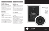
IW5, IW6, IW8 Specifications
2
Side and Rear Views (Typical)
Height
Cutout
Height
Features & Performance
Woofer
1
Tweeter
2
Crossovers
Crossover Frequency
Impedence
Frequency Response
Frequency Range
Power Handling
Sensitivity
Environmental
Temperature
Humidity
Dimensions
3
Height
Width
Depth
Minimum Mounting Depth
Recommended Cutout Size
Construction
Baffle
Grille
Mounting
IW5
10.42 in (265 mm)
7.90 in (201 mm)
3.18 in (81 mm)
3.00 in (77 mm)
9.80 in (249 mm) high,
7.30 in (186 mm) wide
ABS plastic, black
Steel with textured finish, paintable, magnetically-held zero bezel frameless
Flush wall mount using six integral spring-loaded toggle clamps, 1.35 in (34 mm)
maximum surface thickness
41° to 104° F (5° to 40° C)
10% to 90% RH (non-condensing)
For indoor use only
Connections
Input
Maximum Wire Size
(2) spring terminals
10 AWG
IW6 IW8
5.25 in (134 mm)
0.98 in (25 mm)
4th order hybrid
2.5 kHz
8 Ω nominal
55 Hz - 20 kHz (±3 dB)
45 Hz to 20 kHz (-10 dB)
100 watts program
88.0 dB @ (W/m)
1. Woven poly-glass composite with rubber surround, vented pole piece and steel basket
2. Advanced synthetic polymer dome, ferrofluid cooling
3. Dimensions shown are per speaker, positioned vertically
6.50 in (165 mm)
0.98 in (25 mm)
4th order hybrid
2.5 kHz
8 Ω nominal
53 Hz - 20 kHz (±3 dB)
45 Hz to 20 kHz (-10 dB)
125 watts program
89.0 dB @ (W/m)
8.00 in (203 mm)
0.98 in (25 mm)
4th order hybrid
2.5 kHz
8 Ω nominal
48 Hz - 20 kHz (±3 dB)
40 Hz to 20 kHz (-10 dB)
150 watts program
89.5 dB @ (W/m)
Weight
3
4.46 lb (2.1 kg)
Available Models
Available Accessories
Aspire 5.25” 2-Way
In-Wall Speaker, Pair,
White Textured
ASPIRE IW5-W-T
SPKA-NCTP-IW500
New-Construction
Speaker Templates
11.86 in (301 mm)
8.98 in (228 mm)
3.80 in (97 mm)
3.62 in (92 mm)
11.20 in (285 mm) high,
8.30 in (211 mm) wide
4.42 lb (2.1 kg)
Aspire 6.5” 2-Way
In-Wall Speaker, Pair,
White Textured
ASPIRE IW6-W-T
SPKA-NCTP-IW600
New-Construction
Speaker Templates
13.91 in (354 mm)
10.45 in (266 mm)
4.25 in (108 mm)
4.08 in (104 mm)
13.30 in (338 mm) high,
9.80 in (249 mm) wide
7.01 lb (3.2 kg)
Aspire 8” 2-Way
In-Wall Speakers, Pair,
White Textured
ASPIRE IW8-W-T
SPKA-NCTP-IW800
New-Construction
Speaker Templates
SPECIFICATION
Depth
Width
Cutout
Width
Minimum
Mounting
Depth
The following table provides corrective action for possible trouble situations.
If further assistance is required, please contact a Crestron customer service
representative.
Further Inquiries
Future Updates
TROUBLE
POSSIBLE CAUSE(S)
CORRECTIVE ACTION
No sound or
intermittent
sound from
speakers.
Cable connection
error.
Verify cable connections
between amplifier and speakers.
Amplifier not receiving
input signal or amplifier
malfunction.
Verify amplifier is functioning correctly,
that it is receiving an input signal and
that correct input source is selected.
Faulty device in system. Verify all devices in system are
functioning properly.
Constant
noise such as
buzz, hum, or
hiss from
speakers.
System grounding fault. Verify system grounding.
Poor low
frequency
output.
Incorrect polarity
connection at speaker.
Verify speaker connection polarity
(+ on speaker to + on amplifier).
3
Problem Solving
Troubleshooting
To locate specific information or resolve questions after reviewing this guide,
contact Crestron's True Blue Support at 1-888-CRESTRON [1-888-273-7876]
or refer to the listing of Crestron worldwide offices on the Crestron Web site
(www.crestron.com/offices) for assistance within a particular geographic region.
To post a question about Crestron products, log onto the Online Help section of
the Crestron Web site (www.crestron.com/onlinehelp).
First-time users must
establish a user account to fully benefit from all available features.
As Crestron improves functions, adds new features and extends the
capabilities of the Aspire IW5, IW6, and IW8, additional information may
be made available as manual updates. These updates are solely electronic
and serve as intermediary supplements prior to the release of a complete
technical documentation revision.
Check the Crestron Web site periodically for manual update avail
ability and
its relevance. Updates are identified as an “Addendum” in the Download
column.
-
 1
1
-
 2
2


Crestron on wall speaker Quick Start
- Category
- Soundbar speakers
- Type
- Quick Start
Ask a question and I''ll find the answer in the document
Finding information in a document is now easier with AI
Related papers
-
Crestron IC8DT Quick Start
-
-
-
-
-
-
-
-
-
Other documents
-
 NHT CS-6.3 Ci User manual
-
MartinLogan IC6-ST User manual
-
 Artison ARCHT-6-SSTT Installation guide
-
 Athena Technologies AS-IC6ST User manual
-
Triad TS-IW83 Quick start guide
-
Frigidaire FHWC3060LSA Installation guide
-
Tannoy iw6 DS User manual
-
 Crestron electronic TPS-15L User manual
-
-
Elan TP4RBKT-W User manual


