Page is loading ...

24" (61 cm) Wide
LAUNDRY CENTER
Washer- Electric Dryer
f
CENTRO DE LAVANDERIA
de 24" (61 cm) de ancho
Lavadora - Secadora eldctrica
Models/Modelos 110. 80754, 88752
v
i
,_1,//j../l_ 41/ -_r_/,
\
8576659 Sears Roebuck and Co., Hoffman Estates, IL 60179 U.S.A. www.sears.com

TABLEOF CONTENTS
PROTECTION AGREEMENTS ....................................................... 2
WARRANTY ..................................................................................... 3
WASHER/DRYER SAFETY ............................................................ 4
INSTALLATION INSTRUCTIONS .................................................. 5
Tools and Parts ............................................................................ 5
Alternate Parts .............................................................................. 5
Location Requirements ................................................................ 6
Drain System ................................................................................ 7
Electrical Requirements ................................................................ 7
Electrical Connection ................................................................... 9
Venting Requirements ............................................................... 14
Install Leveling Legs .................................................................. 15
Remove Foam Packing ............................................................. 15
Connect Drain Hose .................................................................. 15
Connect Inlet Hoses .................................................................. 16
Secure Drain Hose .................................................................... 16
Plan Vent System ...................................................................... 17
Install Vent System .................................................................... 18
Level Laundry Center ................................................................ 18
Connect Vent ............................................................................. 18
Complete Installation ................................................................. 18
WASHER USE .............................................................................. 19
Starting Your Washer ................................................................ 19
Cycles ........................................................................................ 20
Rinse and Spin .......................................................................... 20
Drain and Spin ........................................................................... 20
Understanding Washer Cycles .................................................. 21
Normal Sounds .......................................................................... 21
LAUNDRY TIPS ............................................................................ 21
Loading ...................................................................................... 21
DRYER USE ................................................................................. 22
Starting Your Dryer .................................................................... 22
Stopping and Restarting ........................................................... 22
Loading ...................................................................................... 22
Drying, Cycle and Temperature Tips ........................................ 23
Cycles ........................................................................................ 23
LAUNDRY CENTER CARE ......................................................... 24
Cleaning the Laundry Center Location ..................................... 24
Cleaning Your Washer ............................................................... 24
Water Inlet Hoses ...................................................................... 24
Cleaning the Lint Screen ........................................................... 24
Cleaning the Dryer Interior ........................................................ 25
Removing Accumulated Lint ..................................................... 25
Vacation, Storage and Moving Care ......................................... 25
TROUBLESHOOTING WASHER ................................................ 26
TROUBLESHOOTING DRYER .................................................... 28
PROTECTION AGREEMENTS
Master Protection Agreements
Congratulations on making a smart purchase. Your new
Kenmore ®product is designed and manufactured for years of
dependable operation. But like all products, it may require ive
maintenance or repair from time to time. That's when having a
Master Protection Agreement can save you money and
aggravation.
Purchase a Master Protection Agreement now and protect
yourself from unexpected hassle and expense.
The Master Protection Agreement also helps extend the life of
your new product. Here's what's included in the Agreement:
v' Expert service by our 12,000 professional repair specialists
v' Unlimited service and no charge for parts and labor on all
covered repairs
v' "No-lemon" guarantee - replacement of your covered
product if four or more product failures occur within twelve
months
v' Product replacement if your covered product can't be fixed
v' Annual ive Maintenance Check at your request - no extra
charge
v' Fast help by phone - phone support from a Sears technician
on products requiring in-home repair, plus convenient repair
scheduling
v' Power surge protection against electrical damage due to
power fluctuations
v' Rental reimbursement if repair of your covered product takes
longer than promised
Once you purchase the Agreement, a simple phone call is all that
it takes for you to schedule service. You can call anytime day or
night, or schedule a service appointment online.
Sears has over 12,000 professional repair specialists, who have
access to over 4.5 million quality parts and accessories. That's
the kind of professionalism you can count on to help prolong the
life of your new purchase for years to come. Purchase your
Master Protection Agreement today!
Some limitations and exclusions apply. For prices and
additional information, call 1-800-827-6655.
Sears Installation Service
For Sears professional installation of home appliances, garage
door openers, water heaters, and other major home items, in the
U.S.A. call 1-800-4-MY-HOME ®.

WARRANTY
Full One-Year Warranty on Mechanical and Electrical Parts
For one year from the date of purchase, when this laundry center
is installed and operated according to the instructions provided in
this Use and Care Guide, Sears will repair this laundry center, free
of charge, if defective in material or workmanship.
NOTE: Exhausting your laundry center with a plastic vent will
void this warranty. See "Installation Instructions" for the complete
exhaust requirements for this laundry center.
Limited Five-Year Warranty on Gearcase Parts
For the second through fifth years from the date of purchase,
Sears will replace any gearcase parts that are defective in
material or workmanship. You will be charged for labor after the
first year.
Limited Ten-Year Warranty on Plastic Tub
For the second through tenth years from the date of purchase,
Sears will replace the plastic tub if defective in material or
workmanship. You will be charged for labor after the first year.
Warranty Restriction
If the laundry center is subject to other than private family use,
the above warranty coverage is effective for only 90 days.
Warranty Service
Warranty service is available by contacting the nearest Sears
Service Center. This warranty applies only while the product is in
use in the United States.
This warranty gives you specific legal rights and you may also
have other rights which vary from state to state.
For Sears warranty information or to contact a Sears Service
Center, please reference the service numbers located on the
back page of this manual.
Sears, Roebuck and Co.
D/817WA, Hoffman Estates, IL 60179
Product Record
In the space below, record your complete model number, serial
number, and purchase date. You can find this information on the
model and serial number label, located at the top inside dryer
door well.
Have this information available to help you quickly obtain
assistance or service when you contact Sears concerning your
appliance.
Model number
Serial number
Purchase date
Inlet Hose replacement date
Inlet Hose replacement date
Inlet Hose replacement date
Replace inlet hoses after 5 years of use to reduce the risk of hose
failure.
Save these instructions and your sales receipt for future
reference,

WASHER/DRYER SAFETY
Your safety and the safety of others are very important.
We have provided many important safety messages in this manual and on your appliance. Always read and obey all safety
messages.
This is the safety alert symbol.
This symbol alerts you to potential hazards that can kill or hurt you and others.
All safety messages will follow the safety alert symbol and either the word "DANGER" or "WARNING."
These words mean:
You can be killed or seriously injured if you don't immediately
follow instructions.
You can be killed or seriously injured if you don't follow
instructions.
All safety messages will tell you what the potential hazard is, tell you how to reduce the chance of injury, and tell you what can
happen if the instructions are not followed.
iMPORTANT SAFETY INSTRUCTIONS
WARNUNG: To reduce the risk of fire, electric shock, or injury to persons when using the washer/dryer, follow basic
precautions, including the following:
m Read a(( instructions before using the washer/dryer.
m Do not place items exposed to cooking oils in your dryer.
items contaminated with cooking oils may contribute to a
chemical reaction that could cause a bad to catch fire.
m Do not wash or dry artic(es that have been previousiy
cieaned in, washed in, soaked in, or spotted with gasoline,
dry-cleaning solvents, other flammable, or explosive
substances as they give off vapors that could ignite or
explode.
m Do not add gasoline, dry-cleaning solvents, or other
flammable, or explosive substances to the wash water.
These substances give off vapors that could ignite or
explode.
m Do not allow children to play on or in the washer/dryer.
Close supervision of children is necessary when the
washer/dryer is used near children.
m Before the washer/dryer is removed from service or
discarded, remove the doors to the washer/dryer
compartments.
m Do not reach into the washer/dryer if the tub, agitator or
drum is moving.
m Do not install or store the washer/dryer where it will be
exposed to the weather.
m Do not tamper with controls.
m Clean dryer lint screen before or after each load.
m Under certain conditions, hydrogen gas may be produced in
a hot water system that has not been used for 2 weeks or
more. HYDROGEN GAS IS EXPLOSIVE. If the hot water
system has not been used for such a period, before using
the washing machine, turn on all hot water faucets and let
the water flow from each for several minutes. This will
release any accumulated hydrogen gas. As the gas is
flammable, do not smoke or use an open flame during this
time.
m Do not repair or replace any part of the washer/dryer or
attempt any servicing unless specifically recommended in
this Use and Care Guide or in published user-repair
instructions that you understand and have the skills to carry
out.
m Do not use fabric softeners or products to eIiminate static
unless recommended by the manufacturer of the fabric
softener or product.
m Do not use heat to dry articles containing foam rubber or
similarly textured rubber-Iike materials.
m Keep area around the exhaust opening and adjacent
surrounding areas free from the accumulation of lint, dust,
and dirt.
m The interior of the machine and dryer exhaust vent should
be cleaned periodicaUy by qualified service personnel.
m See "Electrical Requirements" section for grounding
instructions.
SAVE THESE iNSTRUCTmONS

INSTALLATION INSTRUCTIONS
Gather the required tools and parts before starting installation.
Read and follow the instructions provided with any tools listed
here.
Tools needed:
#2 Phillips and flat-blade
screwdriver
Adjustable wrench that
opens to 1" (2.5 cm) or
9/16"open-end wrench (for
adjusting dryer feet)
Wire stripper (direct wire
installations)
Tin snips (for new vent
installations)
1A"nut driver or socket
wrench (recommended)
• Caulking gun and
compound (for installing
new exhaust vent)
• Vent clamps
• Wood block (for leveling)
• Ruler or measuring tape
• Level
• Knife
• Pliers
• Scissors
Parts supplied:
Remove parts package from the washer basket. Check that all
parts were included.
OO
B C D
E
A. Water inlet hoses (2)
B. Inlet hose flat washers (4)
C. Rear leveling legs (2)
D. Front leveling legs (2)
E.Plastic strap
F. Drain hose
G. Yellow, single wire hose clamp
H. Silver, double-wire hose clamp
Parts needed:
Check local codes, electrical supply and venting, and read
"Electrical Requirements" and "Venting Requirements" before
purchasing parts.
Mobile home installations require metal exhaust system hardware
available for purchase from your local Sears store or Sears
Service Center. For further information, please call
1-800-4-MY-HOME ®(1-800-469-4663}.
Parts listed are available from your local Sears store or Sears
Service Center. For further information, please call
1-800-4-MY-HOME® (1-800-469-4663).
If You Have You Will Need to Buy
Laundry tub or Sump pump system (if not already
standpipe taller than available)
96" (2.4 m)
1" (2.5 cm) diameter 2" (5 cm) diameter to 1" (2.5 cm)
standpipe diameter standpipe adapter, Part
Number 3363920
Overhead sewer Standard 20 gal. (76 L) 34" (86.4 cm)
tall drain tub or utility sink and sump
pump (available from local plumbing
suppliers)
Floor drain Siphon break, Part Number 285320,
additional drain hose, Part Number
285702 and connector kit,
Part Number 285442
Drain hose too short Drain hose, Part Number 285664 and
connector kit, Part Number 285442
Lint clogged drain Drain protector, Part Number 367031
Water faucets 2 longer water fill hoses:
beyond reach of fill 6 ft (1.8 m) Part Number 76314,
hoses 10 ft (3.0 m) Part Number 350008

ExplosionHazard
Keepflammablemateriamsandvapors,suchas
gasoline,awayfromdryer.
Failuretodosocanresumtindeath,explosion,or fire.
You will need
• A location that allows for proper exhaust installation. See
"Venting Requirements."
• A separate30-amp circuit.
• A grounded electrical outlet located within 2 ft (61 cm) of
either side of the laundry center. See "Electrical
Requirements."
• A sturdy floor to support the laundry center weight (laundry
center, water and load) of 500 Ibs (226.8 kg).
A level floor with a maximum slope of 1" (2.5 cm) under entire
laundry center. Clothes may not tumble properly and
automatic sensor cycles may not operate correctly if laundry
center is not level. Installing on carpet is not recommended.
• A water heater set to deliver 120°F (49°C) water to the
washer.
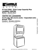
Laundry Center Dimensions
15%"
(39.05 ore)
71 ¾"
(182.25 cm)
23 7/_,,
* Most installations require a minimum 51/2'' (14 cm) clearance
behind the dryer for the exhaust vent with elbow. See "Venting
Requirements."
Minimum installation spacing for recessed area or closet
installation
The following dimensions shown are for the minimum spacings
allowed.
• Additional spacing should be considered for ease of
installation and servicing.
• Hot and cold water faucets located within 4 ft (1.2 m) of the
hot and cold water fill valves, and water pressure of 5-100 psi
(34.5-689.6 kPa). •
The laundry center must not be installed or stored in an area
where it will be exposed to water and/or weather.
Do not operate your washer in temperatures at or below
32°F (0°C). Some water can remain in the washer and can cause
damage in low temperatures. See "Vacation, Storage and Moving
Care" for winterizing information.
Do not operate your dryer at temperatures below 45°F (7°C). At
lower temperatures, the dryer might not shut off at the end of an
automatic cycle. This can result in longer drying times.
Check code requirements. Some codes limit, or do not permit,
installation of the laundry center in garages, closets, mobile
homes, or sleeping quarters. Contact your local building
inspector.
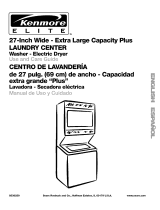
Installation Clearances
The location must be large enough to allow the dryer door to
open fully.
Additional clearances might be required for wall, door and
floor moldings.
For closet installation, with a door, minimum ventilation
openings in the top and bottom of the door are required.
Louvered doors with equivalent ventilation openings are
acceptable.
Rear clearance may be 1" (2.5 cm) when house exhaust
system is lined up directly with dryer exhaust.
© oo o
1"
i 48in_2 -
i (510cr_2)
i
24in,2 -}
(155¢rn2)
1" -->14-23Y8':-_-_'_--1" -_ 1' _ 27!4"-_I I_- 5!/z"
2,5cm 50,64cm 2.5cm 2,5cm (5&22cm} (14cm)
A B
J_
5" (7.6cm)
f
A. Recessed area
B. Side view - closet or confined area
C. Closet door with vents

Mobile Home - Additional Installation Requirements
This laundry center is suitable for mobile home installations.
The installation must conform to the Manufactured Home
Construction and Safety Standard, Title 24 CFR, Part 3280
(formerly the Federal Standard for Mobile Home Construction
and Safety, Title 24, HUD Part 280).
Mobile home installations require:
• Metal exhaust system hardware, which is available for
purchase from your local Sears store or Sears Service Center.
Special provisions must be made in mobile homes to
introduce outside air into the dryer. The opening (such as a
nearby window) should be at least twice as large as the dryer
exhaust opening.
The laundry center can be installed using the standpipe drain
system (floor or wall), the laundry tub drain system, or the floor
drain system. Select the drain hose installation method you need.
See "Alternate Parts."
Standpipe drain system - wall or floor (views A & B)
The standpipe drain requires a minimum diameter standpipe of
2" (5 cm). The minimum carry-away capacity can be no less than
17 gal. (64 L) per minute. A 2" (5 cm) diameter to 1" (2.5 cm)
diameter standpipe adapter kit is available. See "Alternate Parts."
The top of the standpipe must be at least 39" (99 cm) high and no
higher than 96" (2.4 m) from the bottom of the washer.
A B
Laundry tub drain system (view C)
The laundry tub needs a minimum 20 gal. (76 L) capacity. The top
of the laundry tub must be at least 34" (86.4 cm) above the floor
and no higher than 96" (2.4 m) from the bottom of the washer.
Floor drain system (view D)
The floor drain system requires a siphon break that may be
purchased separately. See "Alternate Parts."
The siphon break must be a minimum of 28" (71 cm) from the
bottom of the washer. Additional hoses might be needed.
It is your responsibility
• Tocontact a qualified electrical installer.
• To be sure that the electrical connection is adequate and in
conformance with the National Electrical Code, ANSI/NFPA
70-latest edition and all local codes and ordinances.
A copy of the above code standards can be obtained from:
National Fire Protection Association, One Batterymarch Park,
Quincy, MA 02269.
Tosupply the required 3 or 4 wire, single phase, 120/240 volt,
60 Hz., AC only electrical supply (or 3 or 4 wire, 120/208 volt
electrical supply, if specified on the serial/rating plate) on a
separate 30-amp circuit, fused on both sides of the line. A
time-delay fuse or circuit breaker is recommended. Connect
to an individual branch circuit. Do not have a fuse in the
neutral or grounding circuit.
• Do not use an extension cord.
• If codes permit and a separate ground wire is used, it is
recommended that a qualified electrician determine that the
ground path is adequate.
Electrical Connection
To properly install your laundry center, you must determine the
type of electrical connection you will be using and follow the
instructions provided for it here.
• This dryer is manufactured ready to install with a 3-wire
electrical supply connection. The neutral ground wire is
permanently connected to the neutral conductor (white wire)
within the dryer. Ifthe dryer is installed with a 4-wire electrical
supply connection, the neutral ground wire must be removed
from the internal ground connector (green screw), and
secured under the neutral terminal (center or white wire) of
the terminal block. When the neutral ground wire is secured
under the neutral terminal (center or white wire) of the
terminal block, the dryer cabinet is isolated from the neutral
conductor.
• If local codes do not permit the connection of a neutral
ground wire to the neutral wire, see "Optional 3-wire
connection" section.
• Use a 4-wire conductor cord when the dryer is installed in a
mobile home or an area where local codes do not permit
grounding through the neutral.
If using a power supply cord:
• Use a UL listed power supply cord kit marked for use with
clothes dryers. The kit should contain:
A UL listed 30-amp power supply cord, rated 120/240 volt
minimum. The cord should be type SRD or SRDT and be at
least 4 ft (1.22 m) long. The wires that connect to the dryer
must end in ring terminals or spade terminals with upturned
ends.
• A UL listed strain relief.
D

If your outlet looks like this:
4-wire receptacle (14-30R)
Then choose a 4-wire power supply cord with ring or spade
terminals and UL listed strain relief. The 4-wire power supply
cord, at least 4 ft (1.22 m) long, must have four 10-gauge copper
wires and match a 4-wire receptacle of NEMA Type 14-30R. The
ground wire (ground conductor) may be either green or bare. The
neutral conductor must be identified by a white cover.
If your outlet looks like this:
3-wire receptacle (10-30R)
Then choose a 3-wire power supply cord with ring or spade
terminals and UL listed strain relief. The 3-wire power supply
cord, at least 4 ft (1.22 m) long, must have three 10-gauge copper
wires and match a 3-wire receptacle of NEMA Type 10-30R.
If connecting by direct wire:
Power supply cable must match power supply (4-wire or 3-wire)
and be:
• Flexible armored cable or nonmetallic sheathed copper cable
(with ground wire), protected with flexible metallic conduit. All
current-carrying wires must be insulated.
• 10-gauge solid copper wire. (Do not use aluminum.)
• At least 5 ft (1.52 m) long.
GROUNDING INSTRUCTIONS
[] For a grounded, cord-connected washer/dryer:
This washer/dryer must be grounded. Hnthe event of
malfunction or breakdown, grounding wiII reduce the risk of
electric shock by providing a path of least resistance for
electric current. This washer/dryer uses a cord having an
equipment-grounding conductor and a grounding plug. The
plug must be plugged into an appropriate outlet that is
properly installed and grounded in accordance with alI local
codes and ordinances.
[] For a permanently connected washer/dryer:
This washer/dryer must be connected to a grounded metal,
permanent wiring system, or an equipment-grounding
conductor must be run with the circuit conductors and
connected to the equipment-grounding terminal or lead on
the washer/dryer.
WARNING: Hmproperconnection of the equipment-
grounding conductor can result in a risk of electric shock.
Check with a qualified electrician or service representative or
personnel if you are in doubt as to whether the washer/dryer
is properly grounded. Do not modify the plug on the power
supply cord: if it will not fit the outlet, have a proper outlet
installed by a qualified electrician.
SAVE THESE INSTRUCTIONS

Power Supply Cord Direct Wire
Fire Hazard
Use a new UL listed 30 amp power supply cord,
Use a UL listed strain retief.
Disconnect power before making e_ectrical connections,
Connect neutral wire (white or center wire) to center
terminal (silve0.
Ground wire (green or bare wire) must be connected to
green ground connector.
Connect remaining 2 supply wires to remaining
2 terminals (gold).
Securely tighten all electrical connections.
Failure to do so can result in death, fire, or
electrical shock.
Fire Hazard
Use 10 gauge solid copper wire.
Use a UL listed strain relief.
Disconnect power before making eiectdcal connections.
Connect neutral wire (white or center wire) to center
terminal (silver).
Ground wire (green or bare wire) must be connected to
green ground connector.
Connect remaining 2 supply wires to remaining
2 terminals (gold).
Securely tighten all eJectrical connections.
Failure to do so can result in death, fire, or
electrical shock.
1. Disconnect power, 3.
2. Remove the hold-down screw and terminal block cover.
D
B
S
/
/
C
Install strain relief.
Style 1: Power supply cord strain relief
Remove the screws from a 3/4"(1.9 cm) UL listed strain relief
(UL marking on strain relief). Put the tabs of the two clamp
sections into the hole below the terminal block opening so
that one tab is pointing up and the other is pointing down,
and hold in place. Tighten strain relief screws just enough to
hold the two clamp sections together.
A. Strain relief tab pointing up
B. Hole below terminal block opening
C. Clamp section
D. Strain relief tab pointing down
A. Center silver-colored terminal block screw
B. Hold-down screw
C. Terminal block cover
D. Internal ground conductor screw

Put power supply cord through the strain relief. Be sure that
the wire insulation on the power supply cord is inside the
strain relief. The strain relief should have atight fit with the
dryer cabinet and be in a horizontal position. Do not further
tighten strain relief screws at this point.
Style 2: Direct wire strain relief
Unscrew the removable conduit connector and any screws
from a 3/4"(1.9 cm) UL listed strain relief (UL marking on strain
relief). Put the threaded section of the strain relief through the
hole below the terminal block opening. Reaching inside the
terminal block opening, screw the removable conduit
connector onto the strain relief threads.
Electrical Connection Options
If your home has: And you will be Go to Section
connecting to:
4-wire receptacle A UL listed, 4-wire connection:
(NEMA Type 14-30R) 120/240-volt Power supply cord
minimum,
30-amp, dryer
power supply
cord*
4-wire direct A fused 4-wire connection:
disconnect or Direct Wire
circuit breaker
box*
(12J cm)
3-wire receptacle A UL listed,
(NEMA type 10-30R) 120/240-volt
[_ minimum,
30-amp, dryer
power supply
cord*
3-wire connection:
Power supply cord
3-wire direct A fused 3-wire connection:
disconnect or Direct Wire
circuit breaker
box*
4=
k..__
A. Removable conduit connector
B. Hole below terminal block opening
C. Strain relief threads
Put direct wire cable through the strain relief. The strain relief
should have a tight fit with the dryer cabinet and be in a
horizontal position. Tighten strain relief screw against the
direct wire cable.
Now complete installation following instructions for your type
of electrical connection:
4-wire (recommended)
3-wire (if 4-wire is not available)
*If local codes do not permit the connection of a frame-grounding
conductor to the neutral wire, go to "Optional 3-wire connection"
section.
zzzzzzzzzzzzzzzz __,_,zzzzzzzzzzzzzzzzzz
4-wire connection: Power supply cord
IMPORTANT: A 4-wire connection is required for all mobile
homes and where local codes do not permit the use of 3-wire
C D
connections.
B F
E G
A. 4-wire receptacle (NEMA type 14-30R)
B. 4-prong plug
C. Ground prong
D. Neutral prong
E.Spade terminals with upturned ends
F. _" (1.9 cm) UL listed strain relief
G. Ring terminals
10

1.
2.
Remove center, silver-colored terminal block screw.
Remove neutral ground wire from internal ground conductor
screw. Connect neutral ground wire and the neutral wire
(white or center wire) of power supply cord under center,
silver-colored terminal block screw. Tighten screw.
A
S
....................................B
ED C
A. Centersilver-colored terminalblock screw
B. Neutralground wire
C. Internalground conductor screw - Dotted lineshows
position of NEUTRALground wire before being
moved to center silver-colored terminalblock screw
D. Neutral wire (whiteor center wire)
E.3/4"(1.9cm) UL listed strain relief
Move the green painted screw from the internal to the
external ground conductor location. Connect ground wire
(green or bare) of power supply cord to external ground
conductor screw. Tighten screw.
B
7_
o
iiii
G F E D
A. Neutral wire (white or center wire)
B. Center silver-colored terminal block screw
C. Neutral ground wire
D. External ground conductor screw
E.Ground wire (green or bare) of power supply cord
F Internal ground conductor location
G. 3/4"(1.9 cm) UL listed, strain relief
4. Connect the other wires to outer terminal block screws.
Tighten screws.
5. Tighten strain relief screws.
6. Insert tab of terminal block cover into slot of dryer rear panel.
Secure cover with hold-down screw.
7. You have completed your electrical connection. Now go to
"Venting Requirements."
4-wire connection: Direct Wire
IMPORTANT: A 4-wire connection is required for mobile homes
and where local codes do not permit the use of 3-wire
connections.
Direct wire cable must have 5 ft (1.52 m) of extra length so
laundry center can be moved if needed.
Strip 5" (12.7 cm) of outer covering from end of cable, leaving
bare ground wire at 5" (12.7 cm). Cut 11/2'' (3.8 cm) from
3 remaining wires. Strip insulation back 1" (2.5 cm). Shape ends
of wires into a hook shape.
When connecting to the terminal block, place the hooked end of
the wire under the screw of the terminal block (hook facing right),
squeeze hooked end together and tighten screw. See example
below.
1.
2.
Remove center, silver-colored terminal block screw.
Remove neutral ground wire from internal ground conductor
screw. Connect neutral ground wire and place the hooked
end (hook facing right) of the neutral wire (white or center
wire) of direct wire cable under the center screw of the
terminal block. Squeeze hooked ends together. Tighten
screw.
A
,,S_
........................................B
A. Center silver-colored terminal block screw
B. Neutral ground wire
C. Internal ground conductor screw - Dotted line shows
position of NEUTRAL ground wire before being
moved to center silver-colored terminal block screw
D. Neutral wire (white or center wire)
E._/4" (1.9 cm) UL listed strain relief
11

3=
4=
Move the green painted screw from the internal to the 1.
external ground location. Connect ground wire (green or bare) 2.
of power supply cable to external ground conductor screw.
Tighten screw.
B
i--
o
A ......... __
............... C
A. Neutral wire (white or center wire)
B. Center silver-colored terminal block screw
C. Neutral ground wire
D. External ground conductor screw
E.Ground wire (green or bare) of power supply cable
F Internal ground conductor location
G. 3/4"(!.9 cm) UL listed, strain relief
Place the hooked ends of the other power supply cable wires
under the outer terminal block screws (hooks facing right).
Squeeze hooked ends together. Tighten screws.
5. Tighten strain relief screw.
6. Insert tab of terminal block cover into slot of dryer rear panel.
Secure cover with hold-down screw.
7. You have completed your electrical connection. Now go to
"Venting Requirements."
3-wire connection: Power supply cord
Use where local codes permit connecting cabinet-ground
conductor to neutral wire.
B D E
A ............
C G F
A. 3-wire receptacle (NEMA type 10-30R)
B. 3-wire plug
C. Ground prong
D. Spade terminals with up turned ends
EL_" (1.9 cm) UL listed strain relief
E Ring terminals
G. Neutral (white or center wire)
Loosen or remove center, silver-colored terminal block screw.
Connect neutral wire (white or center wire) of power supply
cord to the center, silver-colored terminal screw of the
terminal block. Tighten screw.
B
s
S
C
D
A.Neutral wire (white or center wire)
B.Center silver-colored terminalblock screw
C.Neutral ground wire
D.Internalground conductor screw
E.3/_,,(1.9cm) UL listed, strain relief
3. Connect the other wires to outer terminal block screws.
Tighten screws.
4. Tighten strain relief screws.
5. Insert tab of terminal block cover into slot of dryer rear panel.
Secure cover with hold-down screw.
6. You have completed your electrical connection. Now go to
"Venting Requirements."
3-wire connection: Direct Wire
Use where local codes permit connecting cabinet-ground
conductor to neutral wire.
Direct wire cable must have 5 ft (1.52 m) of extra length so
laundry center can be moved if needed.
Strip 31/2'' (8.9 cm) of outer covering from end of cable. Strip
insulation back 1" (2.5 cm). If using 3-wire cable with ground
wire, cut bare wire even with outer covering. Shape ends of wires
into a hook shape.
When connecting to the terminal block, place the hooked end of
the wire under the screw of the terminal block (hook facing right),
squeeze hooked end together and tighten screw.
12

1=
2.
Loosen or remove center, silver-colored terminal block screw.
Place the hooked end of the neutral wire (white or center wire)
of direct wire cable under the center screw of terminal block
(hook facing right). Squeeze hooked end together. Tighten
screw.
E
A. Neutral wire (white or center wire)
B. Center sliver-colored terminal block screw
C. Neutral ground wire
D. Internal ground conductor screw
E. 3/4"(1.9 cm) UL listed, strain relief
Place the hooked ends of the other power supply cable wires
under the outer terminal block screws (hooks facing right).
Squeeze hooked ends together. Tighten screws.
4. Tighten strain relief screw.
5. Insert tab of terminal block cover into slot of dryer rear panel.
Secure cover with hold-down screw.
6. You have completed your electrical connection. Now go to
"Venting Requirements."
Optional 3-wire connection
Use for direct wire or power supply cord where local codes
do not permit connecting cabinet-ground conductor to
neutral wire.
1. Remove center, silver-colored terminal block screw.
2. Remove neutral ground wire from internal ground conductor
screw. Connect neutral ground wire and the neutral wire
(white or center wire) of power supply cord/cable under
center, silver-colored terminal block screw. Tighten screw.
D
E
A. Neutral wire (white or center wire)
B. Neutral ground wire
C. External ground conductor screw
B
L
C
D. Grounding path determined by a qualified electrician
E. Internal ground conductor location
Connect the other wires to outer terminal block screws.
Tighten screws.
4. Tighten strain relief screws.
5. Move the green painted screw from the internal to the
external ground conductor location. Connect a separate
copper ground wire from the external ground conductor
screw to an adequate ground.
6. Insert tab of terminal block cover into slot of dryer rear panel.
Secure cover with hold-down screw.
13

• Remove excess flexible metal vent to avoid sagging and
kinking that may result in reduced airflow and poor
performance.
Fire Hazard
Use a heavy metal vent.
Do not use a plastic vent.
Do not use a metal foi vent,
Failure to follow these instructions can result in death
or fire.
• Do not install flexible metal vent in enclosed walls, ceilings or
floors.
Elbows
45° elbows provide better airflow than 90° elbows.
J I
Good Better
WARNING: To reduce the risk of fire, this laundw center
MUST BE EXHAUSTED OUTDOORS,
IMPORTANT: Observe all governing codes and ordinances.
The dwer exhaust must not be connected into any gas vent,
chimney, wall, ceiling, or a concealed space of a building.
If using an existing vent system
• Clean lint from the entire length of the system and make sure
exhaust hood is not plugged with lint.
Clamps
• Use clamps to seal all joints.
• Exhaust vent must not be connected or secured with screws
or other fastening devices that extend into the interior of the
duct. Do not use duct tape.
Clamp
• Replace any plastic or metal foil vent with rigid or flexible
heavy metal vent.
• Review Vent system chart. Modify existing vent system if
necessaw to achieve the best drying performance.
If this is a new vent system
Vent material
• Use a heavy metal vent. Do not use plastic or metal foil vent.
• 4" (10.2 cm) heavy metal exhaust vent and clamps must be
used. DURASAFE TM venting products are recommended.
4" (10.2cm) heavymetal exhaust vent
DURASAFE TM vent products can be purchased from your
dealer. For further information, please call
®
1-800-4-MY-HOME (1-800-469-4663) orvisit our website at
www.sears.com.
Rigid metal vent
• For best drying performance, rigid metal vents are
recommended.
• Rigid metal vent is recommended to avoid crushing and
kinking.
Flexible metal vent
• Flexible metal vents are acceptable only if accessible for
cleaning.
• Flexible metal vent must be fully extended and supported
when the laundry center is in its final position.
Exhaust
Recommended hood styles are shown here.
B
(10.2 cra}
A.Louvered hood style
B.Box hood style
The angled hood style (shown here) is acceptable.
4"
"_"k"_/2
(&4era)
• An exhaust hood should cap the vent to keep rodents and
insects from entering the home.
• Exhaust hood must be at least 12" (30.5 cm) from the ground
or any object that may be in the path of the exhaust (such as
flowers, rocks or bushes, snow line, etc.).
• Do not use an exhaust hood with a magnetic latch.
Improper venting can cause moisture and lint to collect
indoors, which may result in:
[] Moisture damage to woodwork, furniture, paint,
wallpaper, carpets, etc.
[] Housecleaning problems and health problems.
14

Excessive Weight Hazard
Use two or more people to move and install
washer/dryer.
Failure to do so can result in back or other injury.
To protect the floor, use a large flat piece of cardboard from the
shipping carton. Gently place the laundry center on its side, on
the cardboard.
Install the rear leveling legs
1. Push legs into holes in rear corners until they snap into place.
2. Check adjustability of rear legs by pushing in one leg. The
other leg should come out. Check both legs. If they do not
move freely, repeat Step 1.
Install the front leveling legs
1. Examine the front leveling legs. Find the diamond marking.
2. Screw front legs by hand, into the holes in the triangular
braces in the front corners. Use wrench to finish turning the
legs until the diamond marking is no longer visible.
3. Stand the laundry center upright.
1. Open the washer lid. The latch under the dryer will keep the
lid open.
2. Pull the foam packing ring out of the washer.
Proper connection of the drain hose protects your floors from
damage due to water leakage. To keep the drain hose from
coming off or leaking, it must be installed according to the
following instructions:
IMPORTANT: To ensure proper installation, this procedure must
be followed exactly.
f. Check the drain hose to see whether it is the proper length.
2. Wet the inside of the straight end of the drain hose with tap
water.
IMPORTANT: Do not use any lubricant other than water.
3. Squeeze ears of the silver, double-wire clamp with pliers to
open. Place clamp over the straight end of the drain hose
1A"(6.4 mm) from the end.
Open clamp. Twist hose back and forth while pushing onto
drain connector on the side of the laundry center. Continue
until hose contacts the ribbed stops on the cabinet.
5. Place clamp over the area marked "CLAMR" Release clamp.
For laundry tub or standpipe drain systems
1. Open the yellow, single-wire clamp and slide over the hooked
end of the drain hose to secure the rubber and corrugated
sections together.
A. Hooked end
B. Drain hose
NOTE: Keep the foam ring and use it when transporting your
laundry center. This packing material is used to keep the washer
tub stable during transport.
2. Put the hooked end of drain hose into laundry tub or
standpipe. Rotate hook to eliminate kinks.
To keep drain water from going back into the washer:
• Do not straighten hooked end of the drain hose and force
excess drain hose into standpipe. Hose should be secure but
loose enough to provide a gap for air.
• Do not lay excess hose on the bottom of the laundry tub.
For use with floor drain
Remove the drain hose hook from the corrugated drain hose. You
may need additional parts. See Floor drain under "Alternate
Parts."
15

Insert a new flat washer (supplied) into each end of the inlet
hoses. Firmly seat the washers in the couplings.
A B
A. Coupling
B. Washer
6. Using pliers, tighten the couplings with an additional two-
thirds turn.
NOTE: Do not overtighten or use tape or sealants on the valve.
Damage to the valves can result.
If you are working in a closet or recessed area
Move the laundry center into its final position and remove
cardboard from under laundry center. Remove the access panel
by removing 3 Phillips-head screws and one bumper, located at
the top of the access panel. Set panel, screws and bumper aside.
Complete hookup of water hoses and (on gas models) the flexible
gas connector through the access area. Replace access panel
upon completion of laundry center installation.
Connect the inlet hoses to the water faucets
Make sure the washer basket is empty.
2. Attach the hose labeled hot to the hot water faucet. Screw on
coupling by hand until it is seated on the washer.
3. Attach the hose labeled cold to the cold water faucet. Screw
on coupling by hand until it is seated on the washer.
4. Using pliers, tighten the couplings with an additional two-
thirds turn.
NOTE: Do not overtighten or use tape or sealants on the valve.
Damage to the valves can result.
Clear the water lines
• Run water through both faucets and inlet hoses, into a
laundry tub, drainpipe or bucket to get rid of particles in the
water lines that might clog the inlet valve screens.
• Check the temperature of the water to make sure that the hot
water hose is connected to the hot water faucet and that the
cold water hose is connected to the cold water faucet.
Connect the inlet hoses to the washer
1. Attach the hot water hose to the bottom inlet valve. Attaching
the hot water hose first makes it easier to tighten connection
with pliers.
2. Screw on coupling by hand until it is seated on the washer.
3. Using pliers, tighten the couplings with an additional two-
thirds turn.
NOTE: Do not overtighten or use tape or sealants on the valve.
Damage to the valves can result.
S
A. Cold water inlet valve (top)
B. Hot water inlet valve (bottom)
4. Attach the cold water hose to the top inlet valve.
5. Screw on coupling by hand until it is seated on the washer.
Check for leaks
7. Turn on the water faucets and check for leaks. A small
amount of water might enter the washer. You will drain this
later.
NOTE: Replace inlet hoses after 5 years of use to reduce the risk
of hose failure. Record hose installation or replacement dates for
future reference.
• If you connect only one water hose, you must cap off the
remaining water inlet port.
• Periodically inspect and replace hoses if bulges, kinks, cuts,
wear, or leaks are found.
• The apparatus must be connected to the water faucets using
the new hoses. Do not use old hoses.
1. Move the laundry center to its final location and remove any
cardboard used to move the laundry center.
2. Locate the plastic strap included in the parts package.
(2Z>
Beaded tie strap
3. Wrap the drain hose to the laundry tub leg or standpipe with
the plastic strap (A or B below) and secure.
B C
If the water faucets and the drain standpipe are recessed, put
the hooked end of the drain hose in the standpipe. Tightly
wrap the plastic strap around the water inlet hoses and the
drain hose (C above).
16

Refer to the manufacturer's instructions provided with the vent
Choose your exhaust installation type system.
Recommended exhaust installations
Typical installations vent the dryer from the rear of the washer/
dryer. Other installations are possible.
D
A. Dryer E. Elbow
B. Rigid metal or E Clamps
flexible metal vent G. Elbow
C. Clamps H. Exhaust hood
D. Wall
[',\
'\j ..........
i i
1,
\ ,
",,,j ............... '\,\, .................
B C
A. Loop system with standard elbows
B. Loop system with one offset and one standard elbow
C. Vent system with one periscope (2" [5 cm] clearance)
NOTE: The following kits for close clearance alternate
installations are available for purchase. To order, please call
1-800-4-MY-HOME ®(1-800-469-4663}.
• Over-the-Top Installation:
Part Number 26-49900
• Periscope Installation (For use with dryer vent to wall vent
mismatch):
Optional exhaust installations
This laundry center can be converted to exhaust out the right or
left side. To convert the laundry center, use Side Exhaust Kit Part
Number 279823. Ifyour laundry center was previously exhausted
from the right or left side, it can be converted to rear exhaust by
using standard offset connections. To cover the hole in the side,
one of the following plugs can be added:
692790 (white)
3979370 (graphite)
3977784 (biscuit)
Follow the instructions in the kit to install. Kits are available from
your local Sears store or Sears Service Center.
Part Number 26-49901 - Less than 5" (12.7 cm) mismatch
Part Number 26-49908 - 5" (12.7 cm) to 18" (45,7 cm)
mismatch
Part Number 26-49904 - 18" (45.7 cm) to 29" (73.7 cm)
mismatch
Part Number 26-49905 - 29" (73,7 cm) to 50" (127 cm)
mismatch
Special provisions for mobile home installations
The exhaust vent must be securely fastened to a noncombustible
portion of the mobile home structure and must not terminate
beneath the mobile home, Terminate the exhaust vent outside,
i i
= =
= =
iii I
i;:?
J
B C
A. Standard rear offset exhaust installation
B. Rear exhaust for offset close clearance connection
C. Left or right side exhaust installation
Alternate installations for close clearances
Venting systems come in many varieties. Select the type best for
your installation. Three close-clearance installations are shown.
Determine vent path
• Select the route that will provide the straightest and most
direct path outdoors.
• Plan the installation to use the fewest number of elbows and
turns.
• When using elbows or making turns, allow as much room as
possible,
17

• Bend vent gradually to avoid kinking.
• Use the fewest 90 °turns possible.
Determine vent length and elbows needed for best
drying performance
• Use the Vent system chart below to determine type of vent
material and hood combinations acceptable to use.
NOTE: Do not use vent runs longer than those specified in
the Vent system chart. Exhaust systems longer than those
specified will:
• Shorten the life of the dryer.
• Reduce performance, resulting in longer drying times and
increased energy usage.
The Vent system chart provides venting requirements that will
help to achieve the best drying performance.
Vent system chart
NOTE: Side exhaust installations add a 90° turn inside the
laundry center. To determine maximum exhaust length, add one
90° turn to the chart.
Number of Type of Vent Box or Angled
go° turns Louvered hoods
or elbows hoods
0 Rigid metal 43 ft (13.1 m) 36 ft (11.0 m)
Flexible metal 30 ft (9.1 m) 24 ft (7.3 m)
1 Rigid metal 33 ft (10.1 m) 26 ft (7.9 m)
Flexible metal 24 ft (7.3 m) 18 ft (5.5 m)
2 Rigid metal 24 ft (7.3 m) 16 ft (4.9 m)
Flexible metal 16 ft (4.9 m) 10 ft (3.0 m)
1.
2.
3.
Install exhaust hood. Use caulking compound to seal exterior
wall opening around exhaust hood.
Connect vent to exhaust hood. Vent must fit inside exhaust
hood. Secure vent to exhaust hood with 4" (10.2 cm) clamp.
Run vent to dryer location. Use the straightest path possible.
See "Determine vent path" in "Plan Vent System." Avoid 90°
turns. Use clamps to seal all joints. Do not use duct tape,
screws or other fastening devices that extend into the interior
of the vent to secure vent.
Properly leveling your laundry center averts excessive noise and
vibration.
1. Check the levelness of the laundry center by placing a level
on the top edge of the washer, first side to side, then front to
back.
2.
If the laundry center is not level, prop up the front with a
wood block and adjust the feet up or down as necessary.
Remove wood block and lower laundry center. Repeat this
step until the laundry center is level.
1. Using a 4" (10.2 cm) clamp, connect vent to exhaust outlet in
laundry center. If connecting to existing vent, make sure the
vent is clean. The vent must fit over the exhaust outlet and
inside the exhaust hood. Make sure the vent is secured to
exhaust hood with a 4" (10.2 cm) clamp.
2. Move laundry center into its final position. Do not crush or
kink vent. Make sure laundry center is level.
::::: :: ::::
1. Check that all parts are now installed. If there is an extra part,
go back through the steps to see which step was skipped.
2. Check that you have all of your tools.
3. Dispose of/recycle all packaging materials. Keep the plastic
foam for use if the laundry center should be transported.
4. Check the laundry center's final location. Be sure the vent is
not crushed or kinked.
5. Check that the laundry center is level and front leveling feet
are tight. See "Level Laundry Center."
6. For power supply cord installation, plug into an outlet. For
direct wire installation, turn on power.
7. Check that the water faucets are on.
8. Check for leaks around faucets and inlet hoses.
g. Remove the blue protective film on the console and any tape
remaining on the laundry center.
10. Read "Washer Use" and "Dryer Use."
11. Wipe the dryer drum interior thoroughly with a damp cloth to
remove any dust.
12. To test the washer, measure 1/2the normal recommended
amount of detergent and pour it into the washer. Close the lid.
Select HEAVY DUTY and pull out the Cycle Control knob.
Allow the washer to complete one whole cycle.
13. To test the dryer, set the dryer on a full heat cycle (not an air
cycle) for 20 minutes and start the dryer.
If the dryer will not start, check the following:
• Controls are set in a running or "On" position.
• PUSH TO START DRYER button has been firmly pushed.
• Laundry center is plugged into an outlet and/or electrical
supply is on.
• Household fuse is intact and tight, or circuit breaker has
not tripped.
• Dryer door is closed.
14. When the dryer has been running for 5 minutes, open the
dryer door and feel for heat. Ifyou feel heat, cancel cycle and
close the door.
If you do not feel heat, turn off the dryer and check the
following:
• There may be 2 household fuses or circuit breakers for
the dryer. Check to make sure both fuses are intact and
tight, or that both circuit breakers have not tripped. If
there is still no heat, contact a qualified technician.
NOTE: You may notice a burning odor when dryer is first heated.
This odor is common when the heating element is first used. The
odor will go away.
18

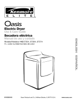
WASHER USE
SPt/V
WATERTEMP WATERLEVEL
HEAVYDUTY
RINSE
...............................................................................10 REGULAR
GEI_T[E
SHORT
PERMANENT
PRESS
SPIN
MEBUUM
WARM WAI{M LOAD
SMALL lARGE
COL{) WARM LOAD LOAD
68L_ HOT O ®
e RESET
SOAK
KNIT/DEL|CATE
Fire Hazard
Never pmace items in the washer that are dampened
with gasoline or other flammable fluids°
No washer can completely remove oH,
Do not dry anything that has ever had any type of oH on
it (including cooking oils).
Doing so can resumt in death, expmosion, or fire,
WARNING: To reduce the risk of fire, electric shock, or injury to
persons, read the IMPORTANT SAFETY INSTRUCTIONS before
operating this appliance.
The following is a guide to starting your washer. Periodic
references to other sections of this manual provide more detailed
information.
1. Pour measured powdered or liquid detergent into the washer.
If desired, add powdered or liquid color safe bleach.
2. Place a load of sorted clothes in the washer.
• Load evenly to maintain washer balance. Mix large and
small items. See "Loading."
• Items should move easily through the wash water.
Overloading can cause poor cleaning.
3. Close the washer lid.
4. Turn the WATER LEVEL selector knob to the correct setting
for your wash load and the type of fabric being washed.
WATER LEVEL
ME_gOM
LOA_
LOA_ LeAD
® 0
RESET
• Choose a load size that allows the load to move freely for
best fabric care. See "Loading."
• You may change the load size selection after the washer
has started filling by turning the selector to a different
setting.
Set the WATER TEMP selector to the correct setting for the
type of fabric and soils being washed.
WATER TEMP
W_61 WA_r_
C0LB WAR_4
COLD_f
COLO COLD
Use the warmest water safe for the fabric. Follow garment
label instructions.
Water Temp Use For
Hot Whites and pastels
Heavy soils
Warm Bright colors
Moderate to light soils
Cold Colors that bleed or fade
Light soils
NOTE: In wash water temperatures colder than 60°F (15.6°C),
detergents do not dissolve well. Soils can be difficult to
remove. Some fabrics can retain wear wrinkles and have
increased pilling (the formation of small lint-like bails on the
surface of garments).
Push in the Cycle Control knob and turn it clockwise to the
wash cycle you want. Pull out the Cycle Control knob to start
the washer.
To stop or restart your washer:
• To stop the washer at any time, push in the Cycle Control
knob.
• To restart the washer, close the lid (if open) and pull out
the Cycle Control knob.
19

This section describes the available wash cycles and will help
you make the best cycle selections for your wash loads. Each
cycle is designed for different types of fabric and soil levels.
• The washer pauses briefly throughout each cycle. These
pauses are normal. Refer to "Normal Sounds" for sounds you
may hear during a wash cycle.
• Refer to "Understanding Washer Cycles" to learn what
happens during a wash cycle.
RfNSE
SPtN
SOAK
Heavy Duty
Use this cycle for sturdy or heavily soiled loads. Wash combines
fast-speed agitation and fast-spin speeds.
• Use the Super or Regular settings for heavily soiled and
sturdy fabrics.
• Use the Short setting for light soil and sturdy fabrics.
Permanent Press
The Permanent Press Cycle includes a load-cooling process that
reduces wrinkling. Wash combines fast and slow-speed agitation
and slow spin speeds.
When the timer reaches Pause, the washer will drain and pause
for approximately 2 minutes while some of the wash water is
drained and replaced with rinse water.
Knit/Delicate
Use this cycle for lingerie and loosely knit items. Partway through
the cycle the washer pauses and soaks the load for more gentle
care of lightly soiled delicate items. Wash combines slow-speed
agitation for gentle soil removal and slow spin speeds to reduce
wrinkling.
Soak
The Soak cycle features 4 minutes of agitation followed by an
unlimited soak time to help remove heavy soils and stains that
need pretreatment. You will need to reset the washer to a SPIN
setting to remove water.
• The Soak cycle should be followed by the Heaw Duty or
Permanent Press or Prewash cycle with additional detergent.
NOTE: Hot water is not recommended for soaking. It may set
some stains.
Prewash
Use this cycle to get up to 4 minutes of agitation to help remove
heavy soils and stains that need pretreatment.
• The Prewash cycle should be followed by the Heavy Duty or
Permanent Press cycle with additional detergent.
When using extra detergent for heavily soiled clothes, or washing
special-care items, you may find an extra rinse and spin is
needed.
1. Push in the Cycle Control knob and turn it clockwise to any of
the RINSE settings.
• For fast agitation and spin, use the Heavy Duty cycle.
• For slow agitation and spin, use the Permanent Press
cycle.
2. Set the WATER LEVEL and WATER TEMP controls to the
desired setting.
3. Pull out the Cycle Control knob. The washer fills to the
selected load size, agitates, drains, and spins.
A drain and spin may help shorten drying times for some heavy
fabrics or special-care items by removing excess water.
1. Push in the Cycle Control knob and turn it clockwise to any of
the SPIN settings.
• For a fast spin, use the Heavy Duty cycle.
• For a slow spin, use the Permanent Press cycle.
2. Pull out the Cycle Control knob. The washer drains, then
spins.
2O
/