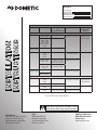
Dometic B57915.XX1C0 Installation guide
- Category
- Thermostats
- Type
- Installation guide
This manual is also suitable for

Read these instructions carefully. These
instructions MUST stay with this product.
USA
SERVICE OFFICE
Dometic Corporation
1120 North Main Street
Elkhart, IN 46514
SERVICE CENTER &
DEALER LOCATIONS
Please Visit:
www.eDometic.com
Roof Top Unit Used With 3314850.000 Air Distribution Box
Description Model Board Built In
OR
Electronic Control Kit
Thermostat Optional Indoor
Temperature
Sensor
Air Conditioner
CCC 2 Controls 541815, 541816
641815, 641816
Board Built In 3314082.000 CCC2-Blk
3314082.011 CCC2-Wht
3311931.000-20′
3311931.012-40′
3311931.020-60′
457915, 459516
459530, 540315
540316, 640310
640312, 640315
B57915, B59516
B57930
3312020.000
CCC 2 Controls
W/Electric Heat
641835 Board Built In
LCD SZ Controls 541915
541916
641915
641916
Board Built In 3313192.000 C/F-Wht
3313192.019 C/F-Blk
N/A
457915, 459516
540315, 540316
B57915, B59516
3313189.000 C/F-Wht
3313189.015 C/F-Blk
3313189.049 C/F/HS-Wht
3313189.056 C/F/HS-Blk
Thermostat Included
With Electronic Control Kit
640310, 640312
640315, 459530
B59530
3313189.000 C/F-Wht
3313189.015 C/F-Blk
LCD SZ Controls
W/Electric Heat
641935 Board Built In 3313194.000 C/F/HS-Wht
3313194.015 C/F/HS-Blk
B57935U, B57935Y
B59536U, B59536Y
Heat Pump
CCC 2 Controls 551816
651815
651816
Board Built In 3314082.000 CCC2-Blk
3314082.011 CCC2-Wht
3311931.000-20’
3311931.012-40’
3311931.020-60’
459186, B59186 3312020.000
LCD SZ Controls 551916
651916
Board Built In 3313193.000 C/F/HP-Wht
3313193.017 C/F/HP-Blk
N/A
459196
B59196
3313189.064 C/F/HP-Wht
3313189.072 C/F/HP-Blk
Thermostat Included
With Electronic Control Kit
This Unit is designed for OEM installation.
RECORD THIS INFORMATION FOR FUTURE
REFERENCE:
Model Number
Serial Number
ADB Model Number
ADB Serial Number
Date Purchased
REVISION G
Form No. 3315085.000 8/18
(French 3315442.000_G)
©2018 Dometic Corporation
LaGrange, IN 46761
INSTALLATION
INSTRUCTIONS

2
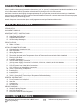
TABLE OF CONTENTS
INTRODUCTION ..................................................................................................................................................................2
DOCUMENT SYMBOLS.......................................................................................................................................................2
IMPORTANT SAFETY INSTRUCTIONS ............................................................................................................................3
A. Recognize Safety Information ...................................................................................................................................3
B. Understand Signal Words ..........................................................................................................................................3
C. Supplemental Directives ............................................................................................................................................ 3
D. General Safety Messages .........................................................................................................................................3
SPECIFICATIONS ................................................................................................................................................................4
A. Table - Unit Data ........................................................................................................................................................4
B. Roof Requirements ....................................................................................................................................................5
INSTALLATION INSTRUCTIONS .......................................................................................................................................6
A. Choosing Proper Location For Unit ...........................................................................................................................6
B. Roof Preparation .......................................................................................................................................................7
C. Wiring Requirements .................................................................................................................................................8
D. Choosing Thermostat Location ..................................................................................................................................9
E. Thermostat, Optional Indoor Temperature Sensor & Thermostat Communication Cable Installation ......................9
F. Placing Unit On Roof ...............................................................................................................................................10
G. Installation Preparation ............................................................................................................................................ 11
H. 120 Vac Power Supply Connection ......................................................................................................................... 11
I. 120 Vac Power Supply Connection For 541X1XA, 551X16A, 6418XXH, & 65181XH Models. ..............................12
J. Duct Divider Installation ........................................................................................................................................... 14
K. LCD SZ System Low Voltage Wire Connections .....................................................................................................14
L. CCC 2 System Low Voltage Wire Connections .......................................................................................................15
M. (CCC2SystemOnly)Conguration ........................................................................................................................16
N. Installing Unit ...........................................................................................................................................................17
O. Installing ADB ..........................................................................................................................................................18
P. (CCC 2 System Only) Reset & Checkout ................................................................................................................ 19
Q. (CCC2SystemOnly)Furnace/AquaTemperatureDierentialSetting ................................................................... 20
GENERAL INFORMATION ................................................................................................................................................21
A. Frost Formation On Cooling Coil .............................................................................................................................21
B. Heat Gain ................................................................................................................................................................21
C. Condensation ..........................................................................................................................................................21
D. Air Distribution .........................................................................................................................................................21
WIRING DIAGRAMS ..........................................................................................................................................................22
A. Simple RV Wiring Diagram ...................................................................................................................................... 22
B. Unit Wiring Diagrams ...............................................................................................................................................23
C. Electronic Control Kit Wiring Diagrams ...................................................................................................................25
DOCUMENT SYMBOLS
Indicates additional information that is NOT related
to physical injury.
Indicates step-by-step instructions.
INTRODUCTION
This air conditioner/heat pump (hereinafter referred to as “unit” or “product”) is designed and intended for installation on the
roof of a Recreational Vehicle (hereinafter referred to as RV) during the time it is manufactured.
Read these instructions and highlight the appropriate steps for your particular procedure before starting the installation.
This unit can be installed by one person with brief help from additional personnel. Use these instructions to ensure a properly
installed, and properly functioning product.
DometicCorporationreservestherighttomodifyappearancesandspecicationswithoutnotice.

3
IMPORTANT SAFETY INSTRUCTIONS
This manual has safety information and instructions to help
users eliminate or reduce the risk of accidents and injuries.
A. Recognize Safety Information
This is the safety alert symbol. It is used to
alert you to potential physical injury hazards.
Obey all safety messages that follow this
symbol to avoid possible injury or death.
B. Understand Signal Words
A signal word will identify safety messages and
property damage messages, and will indicate the
degree or level of hazard seriousness.
indicates a hazardous situation that,
if NOT avoided, could result in death or serious in-
jury.
indicates a hazardous situation that,
if NOT avoided, could result in minor or moderate
injury.
is used to address practices NOT
related to physical injury.
C. Supplemental Directives
Read and follow all safety information and
instructions to avoid possible injury or death.
Read and understand these instructions be-
fore [installing / using / servicing / performing
maintenance on] this product.
Incorrect [installation / operation / servicing /
maintaining] of this product can lead to seri-
ous injury. Follow all instructions.
The installation MUST comply with all ap-
plicable local or national codes, including
the latest edition of the following standards:
U.S.A.
● ANSI/NFPA70, National Electrical Code
(NEC)
● ANSI/NFPA 1192, Recreational Vehicles
Code
CANADA
● CSA C22.1, Parts l & ll, Canadian Electri-
cal Code
● CSA Z240 RV Series, Recreational
Vehicles
D. General Safety Messages
Failure to obey the following warn-
ings could result in death or serious injury:
● This product MUST be [installed / serviced] by a
qualiedservicetechnician.
● Do NOT modifythisproductinanyway.Modica-
tion can be extremely hazardous.
● Do NOT add any devices or accessories to this
product except those specically authorized in
writing by Dometic Corporation.

4
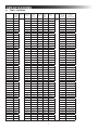
A. Table - Unit Data
Model No. Nominal
Capacity
(BTU HR)
Cooling
Electrical
Rating
Compressor
Rated Load
Amps
Compressor
Locked
Rotor
Amps
Fan Motor
Rated Load
Amps
Fan Motor
Locked
Rotor
Amps
Refrigerant
R-410A
(oz)
Minimum
Wire Size*
AC Circuit
Protection
***Installer
Supplied
Minimum
Generator
Size**
1 Unit / 2 Units
457915.70X 13,500 120 Vac
60 Hz 1 ph
12.4 63.0 2.5 5.8 18.0 12 AWG
Copper
Up to 24'
20 Amp 3.5 kW / 5.0 kW
457915.71X 13,500 12.4 68.0 2.5 5.8 18.0 20 Amp 3.5 kW / 5.0 kW
B57915.71X 13,500 12.4 68.0 2.5 5.8 16.0 20 Amp 3.5 kW / 5.0 kW
B57935U71X 13,500 12.7 68.0 2.7 5.8 16.0 20 Amp 3.5 kW / 5.0 kW
B57935Y71X 13,500 12.7 68.0 2.7 5.8 16.0 20 Amp 3.5 kW / 5.0 kW
459186.70X 15,000 13.3 66.0 2.0 5.6 29.0 20 Amp 3.5 kW / 5.0 kW
459186.71X 15,000 13.3 70.0 2.0 5.6 29.0 20 Amp 3.5 kW / 5.0 kW
B59186.71X 15,000 13.3 70.0 2.0 5.6 29.0 20 Amp 3.5 kW / 5.0 kW
459196.70X 15,000 13.3 66.0 2.0 5.6 29.0 20 Amp 3.5 kW / 5.0 kW
459196.71X 15,000 13.3 70.0 2.0 5.6 29.0 20 Amp 3.5 kW / 5.0 kW
B59196.71X 15,000 13.3 70.0 2.0 5.6 29.0 20 Amp 3.5 kW / 5.0 kW
459516.70X 15,000 13.3 66.0 2.0 5.6 27.5 20 Amp 3.5 kW / 5.0 kW
459516.71X 15,000 13.3 70.0 2.0 5.6 27.5 20 Amp 3.5 kW / 5.0 kW
B59516.71X 15,000 13.3 70.0 2.0 5.6 18.3 20 Amp 3.5 kW / 5.0 kW
459530.70X N/A 8.6 50.0 2.5 5.8 20.0 15 Amp 2.5 kW / 4.0 kW
B59530.71X N/A 8.6 50.0 2.5 5.8 20.0 15 Amp 2.5 kW / 4.0 kW
B59536U71X 15,000 13.2 70.0 2.7 5.6 18.3 20 Amp 3.5 kW / 5.0 kW
B59536Y71X 15,000 13.2 70.0 2.7 5.6 18.3 20 Amp 3.5 kW / 5.0 kW
540315.70X 13,500 12.4 63.0 3.0 8.5 18.5 20 Amp 3.5 kW / 5.0 kW
540315.71X 13,500 12.4 68.0 3.0 8.5 18.5 20 Amp 3.5 kW / 5.0 kW
540316.70X 15,000 13.3 66.0 2.8 7.6 29.5 20 Amp 3.5 kW / 5.0 kW
540316.71X 15,000 13.3 70.0 2.8 7.6 29.5 20 Amp 3.5 kW / 5.0 kW
541815A70X 13,500 12.4 63.0 3.0 8.5 18.5 20 Amp 3.5 kW / 5.0 kW
541815A71X 13,500 12.4 68.0 3.0 8.5 18.5 20 Amp 3.5 kW / 5.0 kW
541816A70X 15,000 13.3 66.0 2.8 7.6 29.5 20 Amp 3.5 kW / 5.0 kW
541816A71X 15,000 13.3 70.0 2.8 7.6 29.5 20 Amp 3.5 kW / 5.0 kW
541915A70X 13,500 12.4 63.0 3.0 8.5 18.5 20 Amp 3.5 kW / 5.0 kW
541915A71X 13,500 12.4 68.0 3.0 8.5 18.5 20 Amp 3.5 kW / 5.0 kW
541916A70X 15,000 13.3 66.0 2.8 7.6 29.5 20 Amp 3.5 kW / 5.0 kW
541916A71X 15,000 13.3 70.0 2.8 7.6 29.5 20 Amp 3.5 kW / 5.0 kW
551816.70X 15,000 12.8 60.0 2.8 7.6 29.5 20 Amp 3.5 kW / 5.0 kW
551816.71X 15,000 12.8 70.0 2.8 7.6 29.5 20 Amp 3.5 kW / 5.0 kW
551816A70X 15,000 12.8 60.0 2.8 7.6 29.5 20 Amp 3.5 kW / 5.0 kW
551816A71X 15,000 12.8 70.0 2.8 7.6 29.5 20 Amp 3.5 kW / 5.0 kW
551916A71X 15,000 12.8 70.0 2.8 7.6 29.5 20 Amp 3.5 kW / 5.0 kW
640310C45X N/A 8.8 5.6 2.6 8.5 20.5 15 Amp 2.5 kW / 4.0 kW
640312.80X 11,000 11.5 53.0 2.6 8.5 20.0 20 Amp 3.5 kW / 5.0 kW
640312.83X 11,000 12.5 63.0 2.6 8.5 18.0 20 Amp 3.5 kW / 5.0 kW
640312C35X 11,000 10.5 53.0 3.5 10.0 19.0 20 Amp 3.5 kW / 5.0 kW
640312C85X 11,000 11.5 53.0 2.6 8.5 20.0 20 Amp 3.5 kW / 5.0 kW
640315.80X 13,500 12.6 63.0 2.6 8.5 18.0 20 Amp 3.5 kW / 5.0 kW
640315.83X 13,500 12.5 63.0 2.6 8.5 19.0 20 Amp 3.5 kW / 5.0 kW
640315.84X 13,500 12.5 63.0 3.5 8.5 19.0 20 Amp 3.5 kW / 5.0 kW
640315C35X 13,500 12.5 61.0 3.5 10.0 17.5 20 Amp 3.5 kW / 5.0 kW
640315C75X 13,500 12.7 52.0 2.6 8.5 14.5 20 Amp 3.5 kW / 5.0 kW
640315C85X 13,500 12.6 63.0 2.6 8.5 18.0 20 Amp 3.5 kW / 5.0 kW
641815.80X 13,500 12.6 63.0 2.6 8.5 19.0 20 Amp 3.5 kW / 5.0 kW
641815C35X 13,500 12.5 61.0 3.5 10.0 17.5 20 Amp 3.5 kW / 5.0 kW
64181C75X 13,500 12.7 52.0 2.6 8.5 14.5 20 Amp 3.5 kW / 5.0 kW
64181C85X 13,500 12.6 63.0 2.6 8.5 19.0 20 Amp 3.5 kW / 5.0 kW
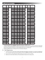
SPECIFICATIONS

5
Model No. Nominal
Capacity
(BTU HR)
Cooling
Electrical
Rating
Compressor
Rated Load
Amps
Compressor
Locked
Rotor
Amps
Fan Motor
Rated Load
Amps
Fan Motor
Locked
Rotor
Amps
Refrigerant
R-410A
(oz)
Minimum
Wire Size*
AC Circuit
Protection
***Installer
Supplied
Minimum
Generator
Size**
1 Unit / 2 Units
641815H75X 13,500 120 Vac
60 Hz 1 ph
12.7 52.0 2.6 8.5 14.5 12 AWG
Copper
Up to 24'
20 Amp 3.5 kW / 5.0 kW
641815H85X 13,500 12.6 63.0 2.6 8.5 19.0 20 Amp 3.5 kW / 5.0 kW
641816.80X Hi Cap 13.4 63.0 2.6 8.5 23.0 20 Amp 3.5 kW / 5.0 kW
641816C35X Hi Cap 12.3 61.0 3.3 8.5 23.0 20 Amp 3.5 kW / 5.0 kW
641816C75X Hi Cap 12.9 52.0 2.6 8.5 21.5 20 Amp 3.5 kW / 5.0 kW
641816C85X Hi Cap 13.4 63.0 2.6 8.5 23.0 20 Amp 3.5 kW / 5.0 kW
641816H75X HI Cap 12.9 52.0 2.6 8.5 21.5 20 Amp 3.5 kW / 5.0 kW
641816H85X Hi Cap 13.4 63.0 2.6 8.5 23.0 20 Amp 3.5 kW / 5.0 kW
641835.80X 13,500 12.6 63.0 2.6 8.5 19.0 20 Amp 3.5 kW / 5.0 kW
641835C35X 13,500 12.5 61.0 3.5 10.0 17.5 20 Amp 3.5 kW / 5.0 kW
641835C75X 13,500 12.7 52.0 2.6 8.5 14.5 20 Amp 3.5 kW / 5.0 kW
641835C85X 13,500 12.6 63.0 2.6 8.5 19.0 20 Amp 3.5 kW / 5.0 kW
641835H75X 13,500 12.7 52.0 2.6 8.5 14.5 20 Amp 3.5 kW / 5.0 kW
641835H85X 13,500 12.6 63.0 2.6 8.5 19.0 20 Amp 3.5 kW / 5.0 kW
641915.80X 13,500 12.6 63.0 2.6 8.5 19.0 20 Amp 3.5 kW / 5.0 kW
641915C35X 13,500 12.5 61.0 3.5 10.0 17.5 20 Amp 3.5 kW / 5.0 kW
641915C75X 13,500 12.7 52.0 2.6 8.5 14.5 20 Amp 3.5 kW / 5.0 kW
641915C85X 13,500 12.6 63.0 2.6 8.5 19.0 20 Amp 3.5 kW / 5.0 kW
641916.80X Hi Cap 13.4 63.0 2.6 8.5 23.0 20 Amp 3.5 kW / 5.0 kW
641916C35X Hi Cap 12.3 61.0 3.3 8.5 23.0 20 Amp 3.5 kW / 5.0 kW
641916C75X Hi Cap 12.9 52.0 2.6 8.5 21.5 20 Amp 3.5 kW / 5.0 kW
641916C85X Hi Cap 13.4 63.0 2.6 8.5 23.0 20 Amp 3.5 kW / 5.0 kW
641935.80X 13,500 12.5 63.0 2.6 8.5 19.0 20 Amp 3.5 kW / 5.0 kW
641935C35X 13,500 12.5 61.0 3.5 10.0 17.5 20 Amp 3.5 kW / 5.0 kW
641935C75X 13,500 12.7 52.0 2.6 8.5 14.5 20 Amp 3.5 kW / 5.0 kW
641935C85X 13,500 12.5 63.0 2.6 8.5 19.0 20 Amp 3.5 kW / 5.0 kW
651815.80X 13,500 13.1 63.0 2.6 8.5 24.0 20 Amp 3.5 kW / 5.0 kW
651815C35X 13,500 12.5 61.0 3.5 10.0 25.0 20 Amp 3.5 kW / 5.0 kW
651815C75X 13,500 12.7 52.0 2.6 8.5 19.0 20 Amp 3.5 kW / 5.0 kW
651815C85X 13,500 13.1 63.0 2.6 8.5 24.0 20 Amp 3.5 kW / 5.0 kW
651815H75X 13,500 12.7 52.0 2.6 8.5 19.0 20 Amp 3.5 kW / 5.0 kW
651815H85X 13,500 13.1 63.0 2.6 8.5 24.0 20 Amp 3.5 kW / 5.0 kW
651816.80X HI Cap 13.4 63.0 2.6 8.5 27.0 20 Amp 3.5 kW / 5.0 kW
651816C35X HI Cap 12.3 61.0 3.3 8.5 24.0 20 Amp 3.5 kW / 5.0 kW
651816C75X Hi Cap 13.0 52.0 2.6 8.5 23.0 20 Amp 3.5 kW / 5.0 kW
651816C85X HI Cap 13.4 63.0 2.6 8.5 27.0 20 Amp 3.5 kW / 5.0 kW
651816H75X Hi Cap 13.0 52.0 2.6 8.5 23.0 20 Amp 3.5 kW / 5.0 kW
651816H85X HI Cap 13.4 63.0 2.6 8.5 27.0 20 Amp 3.5 kW / 5.0 kW
651916.80X HI Cap 13.4 63.0 2.6 8.5 27.0 20 Amp 3.5 kW / 5.0 kW
651916C35X HI Cap 12.3 61.0 3.3 8.5 24.0 20 Amp 3.5 kW / 5.0 kW
651916C75X Hi Cap 13.0 52.0 2.6 8.5 23.0 20 Amp 3.5 kW / 5.0 kW
651916C85X HI Cap 13.4 63.0 2.6 8.5 27.0 20 Amp 3.5 kW / 5.0 kW
* For wire length over 24 ft., consult the National Electrical Code for proper sizing.
** Dometic Corporation gives GENERAL guidelines for generator requirements. These guidelines come from experiences
people have had in actual applications. When sizing the generator, the total power usage of your RV must be considered.
Keep in mind generators lose power at high altitudes and from lack of maintenance.
*** CIRCUIT PROTECTION: Time Delay Fuse or Circuit Breaker Required.
B. Roof Requirements
● A14-1/4″x14-1/4″(±1/8″)squareopening(hereinafterreferredtoas“roofopening”)isrequiredforinstallingthis
unit. This opening is part of the return air system of the unit and MUSTbenishedinaccordancewithNFPA1192.
● Roof construction with rafters/joists support frames on a minimum of 16 inch centers.
● Minimum of 2 inches and maximum of 4 inches distance between roof to ceiling of RV.
SPECIFICATIONS

6
INSTALLATION INSTRUCTIONS
A. Choosing Proper Location For Unit
Thisunitisspecicallydesignedforinstallationontheroof
of an RV. When determining your cooling requirements, the
following should be considered:
● Size of RV;
● Window area (increases heat gain);
● Amount of insulation in walls and roof;
● Geographical location where the RV will be
used;
● Personal comfort level required.
1. For one unit installation: The unit should be
mounted slightly forward of center (front to back)
and centered from side to side.
2. For two unit installations: Install one unit 1/3 and
one unit 2/3’s from front of RV and centered from
side to side.
Itispreferredthattheunitbeinstalledonarelativelyat
and level roof section measured with the RV parked on a
level surface. See table below for maximum acceptable tilt.
Model
Number
Max
Tilt
Model
Number
Max
Tilt
Model
Number
Max
Tilt
457915
B57915
B57935U
B57935Y
459186
B59186
459196
B59196
459516
B59516
459530
15° B59530
B59536U
B59536Y
540315
540316
541815
541816
541915
541916
551816
551916
15° 640310
640312
640315
641815
641816
641835
641915
641916
641935
651815
651816
651916
8°
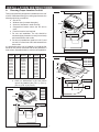
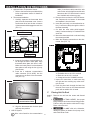
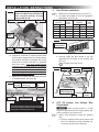
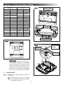
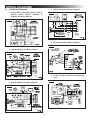
3. After Location Has Been Selected:
a. Check for obstructions in the area where
unit will be installed. See (FIG. 1), (FIG. 2),
(FIG. 3), (FIG. 4), & (FIG. 5).
Model
457915
459186
459196
459516
459530
29-7/8″
34-7/8″
13-1/8″
18″
Front
Dimensions Are Nominal
FIG. 1
Keep This Area Free Of Obstructions
Roof Opening
Center Line Of Unit
FIG. 2
Dimensions Are Nominal
Roof Opening
Keep This Area Free Of Obstructions
Center Line Of Unit
Front
18″
12-7/8″
29-5/8″
27-5/8″
Model
B57915
B57935U
B57935Y
B59186
B59196
B59516
B59530
B59536U
B59536Y
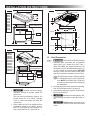
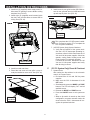
FIG. 3
Dimensions Are Nominal
Keep This Area Free Of Obstructions
Front
Center Line Of Unit
Roof Opening
18″
13″
39-5/8″
29-7/8″
Model
540315, 540316
541815, 541816
541915, 541916
551816, 551916

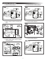
7
FIG. 4
Dimensions Are Nominal
9-1/2″
29″
40″
Roof Opening
Front
Center Line Of Unit
4″
4″
12″
Keep These Areas
Free Of Obstructions
Model
640312
640315
641815
641816
641835
641915
641916
641935
651815
651816
651916
FIG. 5
Dimensions Are Nominal
10-3/8″
29″
40-1/2″
Keep These Areas
Free Of Obstructions
Roof
Opening
Front
Center Line Of Unit
4″
4″
12″
Model
640310C
640312C
640315C
641815C & H
641816C & H
641835C & H
641915C
641916C
641935C
651815C & H
651816C & H
651916C
b. Maintain structural integrity.
Otherwise damage to product and/or RV
could occur.
The roof must be designed to support 130
pounds when RV is in motion. Normally
a 200 lb. static load design will meet this
requirement.
c. Check inside the RV for air distribution box
(hereinafter referred to as "ADB") obstruc-
tions (i.e. door openings, room dividers, cur-
tains,ceilingxtures,etc.).See(FIG.6).
FIG. 6
23-1/8″
21-1/8″
Dimensions Are Nominal
11-9/16″
11-9/16″
21-1/8″
3-7/16″
2-5/8″
3-7/16″
6″ 2-7/8″
Roof Opening
B. Roof Preparation
1. FIRE OR ELECTRICAL SHOCK
HAZARD. Make sure there are no obstacles
(wires, pipes, etc.) inside RV’s [roof / oor /
walls]. Shut OFF gas supply, disconnect 120
Vac power from RV, and disconnect positive (+)
12 Vdc terminal from supply battery BEFORE
drilling or cutting into RV. Failure to obey these
warnings could result in death or serious injury.
Opening Requirements - Before preparing
the ceiling opening, the type of system op-
tions MUST be decided upon. Read all of
the following instructions before beginning
the installation.
2. Carefully mark and cut the required roof opening.
See "B. Roof Requirements" on page (5).
3. Using the roof opening as a guide, cut the match-
ing hole in the ceiling.
4. Maintain structural integrity. Oth-
erwise damage to product and/or RV could oc-
cur.
NEVER create a low spot on RV
roof. Otherwise, water will pool and could cause
a leak.
INSTALLATION INSTRUCTIONS

8
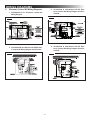
The opening created must be framed to provide
adequate support and prevent air from being
drawn from theroof cavity. Framingstock 3/4″
or more in thickness must be used. Remember
to provide an entrance hole for power supplies,
indoor temperature sensor (if applicable), ther-
mostat communication cable, and furnace wires
(if applicable) at the front of the opening. See
(FIG. 7).
3/4″ Min.
Leave Access For
Power Supply Wiring
FIG. 7
15″ Min. At
Front Of
Opening
Do Not Cut Roof
Structure Or
Rafters
Good-Rafters
Supported By
Cross Beams
Good Location
Between Roof
Rafters
Frame Opening So It
Won't Collapse When
Bolting Down Unit
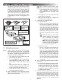
C. Wiring Requirements
1. Route a copper, with ground, 120 Vac supply
wire from the time delay fuse or circuit breaker
box to the roof opening. Use a listed/certied
non metallic - sheathed single strand cable. See
"A. Table - Unit Data" on page (4).
a. This supply wire must be located in the front
portion of the roof opening.
b. The power MUST be on an appropriately
sized separate time delay fuse or circuit
breaker. See "A. Table - Unit Data" on page
(4).
c. Make sure that at least 15″ of supply wire
extends into the roof opening. This ensures
an easy connection at the junction box.
d. Protect the wire where it passes into the
opening with approved method.
2. Route a dedicated 12 Vdc supply wire (18-22)
AWG) from the RV converter (ltered side) or
battery to the roof opening.
When a Comfort Control Center 2 (here-
inafter referred to as CCC 2) thermostat
is being installed with more than 2 zones,
route a dedicated 12 Vdc supply wire
(18-22 AWG) to zone 1 and zone 3 roof
opening.
a. This supply wire must be located in the front
portion of the roof opening.
b. Make sure that at least 15″ of supply wire
extends into the roof opening.
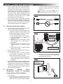
3. Thermostat Communication Cable
a. CCC 2 Thermostat
I. Route a 4 conductor communication ca-
ble from the roof opening to the thermo-
stat mounting location using the shortest
most direct route. Make sure that at least
15″ofthewireextendsintotheroofopen-
ing and 6″ extends from the wall at the
thermostat mounting location. See "D.
Choosing Thermostat Location" on page
(9).
When more than one unit is being
installed (additional zones) with the
CCC 2 thermostat, an additional
4 conductor communication cable
MUST be routed to each additional
unit roof opening. Make sure that
atleast15″ofthewireextendsinto
the roof opening. See (FIG. 47).
b. LCD SZ Thermostat
I. Route a 3 conductor communication ca-
ble, 18 to 22 AWG, from the roof open-
ing to the Liquid Crystal Display Single
Zone (hereinafter referred to a LCD SZ)
thermostat mounting location. Make sure
thatatleast15″ofthewireextendsinto
theroofopeningand6″extendsfromthe
wall at the thermostat mounting location.
See "D. Choosing Thermostat Location"
on page (9).
4. (CCC 2 system only) Optional Indoor Tempera-
ture Sensor
a. Route an indoor temperature sensor (option-
al) from the roof opening to the indoor tem-
perature sensor location. The 2 pin connec-
tor end goes to the roof opening. See indoor
temperature sensor installation instructions
for proper sensor location.
5. If system includes a gas furnace, route two 18
gauge thermostat wires from the furnace to the
roof opening of the unit that will control it. If more
than one furnace is to be used, route the second
set of thermostat wires to the second unit. Make
sure that at least 15″ of wire extends into the
opening.
INSTALLATION INSTRUCTIONS

9
connectors. Refer to the crimp tool manufac-
turer for crimping instructions. See (FIG. 8)
& (FIG. 9).
RJ-11-6C4P connectors MUST be in-
stalled as shown in (FIG. 8) & (FIG. 9).
FIG. 8
FIG. 9
Flat 4-Conductor
Communication Cable
RJ-11-6C4P
Connector
Pin 1
Black
Red
Green
Yellow
b. Route the communication cable through the
2" diameter hole in the wall required for the
thermostat. See (FIG. 10).
FIG. 10
CCC 2 Thermostat
(Rear View)
Wall
6. (CCC 2 system only) If an Energy Management
System (load shed feature) is to be used with
the control, two wires must be routed to the
roof opening of the zone to be managed. The
signal required for this function is normally an
open relay contact. When the EMS calls for the
compressortoshuto,therelaycontactsshould
close. Make sure that at least 15″ of the EMS
wire extends into the roof opening.
7. (CCC 2 system only) If an Automatic Generator
Start (AGS) kit will be installed, an additional 4
conductor communication cable must be routed
from the last unit to the location of the AGS kit.
Follow AGS kit instructions for installation.
D. Choosing Thermostat Location
1. CCC 2 system without an optional indoor tem-
perature sensor and LCD SZ system
a. The proper location of the thermostat is very
important to ensure that it will provide a com-
fortable RV temperature. Observe the follow-
ing rules when selecting a location.
● Locatethethermostat54″abovetheoor.
● Install the thermostat on a partition, not
on an outside wall.
● NEVER expose the thermostat to direct
heat from lamps, sun, or other heat pro-
ducing items.
● Avoid locations close to doors that lead
outside, windows, or adjoining outside
walls.
● Avoid locations close to supply registers
and the air from them.
2. CCC 2 system with an optional indoor tempera-
ture sensor in ALL zones
a. The thermostat may be mounted anywhere
in the RV that is convenient. Try to avoid
hard to reach and hard to see areas.
I. Refer to the instructions provided with the
indoor temperature sensor for details of
installation.
3. When multiple single zone thermostats are be-
ing utilized, each individual thermostat MUST be
installed in the room that the air conditioner is
responsible for cooling to prevent air condition-
ers from attempting to turn on at the same time
and overloading the breaker.
E. Thermostat, Optional Indoor
Temperature Sensor & Thermostat
Communication Cable Installation
1. CCC 2 System
a. The previously run communication cable (4
conductor telephone cable) must be termi-
nated with two (2) RJ-11-6C4P telephone
INSTALLATION INSTRUCTIONS

10
INSTALLATION INSTRUCTIONS
c. Optional Indoor Temperature Sensor
I. Refer to the instructions provided with the
indoor temperature sensor for details of
installation.
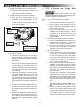
d. Thermostat Installation
I. Carefully separate the thermostat base
plate from the thermostat cover. Insert a
small screw driver into the slot on bottom
of thermostat and disengage the tab. See
(FIG. 11).
FIG. 11
Disengage Tab
CCC 2 Thermostat
II. Insert the 4 conductor communication ca-
ble through the hole in base plate. Align
thermostat base plate with hole in wall.
Make sure base plate is level and attach
base plate to wall using the four (4) sup-
plied screws.
III. Insert the 4 conductor communication
cable connector (RJ-11-6C4P) into the
connector on the back of the thermostat.
See (FIG. 12).
FIG. 12
4 Conductor
Communication Cable
IV. Align the thermostat with the back plate
and snap into position.
2. LCD SZ System
Wire colors listed for the communication
cable (3 conductor cable) match the wire
colors in the unit wire harness and the wire
harness at the LCD SZ electronic control
box. Available wire colors may vary.
a. Remove the cover from the LCD SZ thermo-
stat. Depress tab on bottom of thermostat
and separate it from the base.
b. Insert the previously run communication ca-
ble (3 conductor cable) through the hole in
the base assembly.
c. Cut back the outer cable shield approxi-
mately3inchesandstrip1/4″insulationfrom
each wire.
d. Mount the thermostat level on the wall using
the screws provided.
e. Make the following connections to the ther-
mostat. See (FIG. 13).
FIG. 13
12-
COMMS
12+
● Red/white wire to the 12V+ terminal
● Black wire to the 12V– terminal
● Orange wire to the "COMMS" terminal
f. Inspect all connections to make sure they
are tight and not touching any other termi-
nals or wires.
g. Push the wires back through the base into
the wall. Place cover on the thermostat and
push until an audible click is heard.
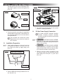
F. Placing Unit On Roof
1. Remove the unit from the carton and discard
carton.
2. LIFTING HAZARD. Use proper
lifting technique and control when lifting product.
Failure to obey this caution could result in injury.
Place unit on the roof.
3. Do NOT slide unit. Otherwise,
damage to gasket (on bottom of unit) may occur,
and could cause a leak.

11
Lift and place the unit over the prepared open-
ing using the gasket on the unit as a guide. See
(FIG. 14).
FIG. 14
Do Not Slide
Lift And Place
Front
4. Place the electronic control box kit (if applicable)
and the ADB kit inside the RV. These boxes con-
tain mounting hardware for the unit and will be
used inside the RV.
This completes the outside work. Minor
adjustments can be done from inside the
RV if required.
G. Installation Preparation
1. Check gasket alignment of the unit over the
roof opening and adjust if necessary. Unit may
be moved from below by slightly lifting. See
(FIG. 15).
FIG. 15
Center Unit From Below
Roof Gasket
2. Remove ADB and mounting hardware from car-
ton. See (FIG. 16).
FIG. 16
Duct Divider
Ceiling
Template
ADB
3. All models in this manual will use a four (4) bolt
pattern for installing the ADB kit.
H. 120 Vac Power Supply Connection
For models 541815A, 541816A, 541915A,
541916A, 551816A, 551916A, 641815H,
641816H, 641835H, 651815H, and 651816H
go to section "I".
1. ELECTRICAL SHOCK HAZARD.
Make sure 120 Vac power is disconnected from
RV. Failure to obey this warning could result in
death or serious injury.
2. ELECTRICAL SHOCK HAZARD.
Provide grounding in compliance with all appli-
cable electrical codes. Failure to obey this warn-
ing could result in death or serious injury.
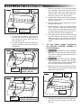
3. Reach up into the return air opening of the
unit and pull down the unit electrical cord and
power supply wires. See (FIG. 17), (FIG. 18) &
(FIG. 19).
INSTALLATION INSTRUCTIONS

12
FIG. 17
Electrical
Cord
Measure Ceiling
Thickness
AC Power
Supply
Models Using Electronic
Control Kit
a. For units with board built in, mount the junc-
tion box with screws to framing in front of
roof opening and install strain relief. See
(FIG. 18) & (FIG. 19).
b. For units with plastic electronic control box,
remove junction box cover. Save screws for
reinstallation.
FIG. 18
Electrical
Cord
AC Power Supply
Low Voltage Wires
Models With Board Built In
Except B57935U, B57935Y,
B59536U & B59536Y
FIG. 19
Electrical
Cord
AC Power
Supply
B57935U, B57935Y,
B59536U, & B59536Y Models
Low Voltage
Wires
4. Route the previously run 120 Vac power supply
wire through the strain relief and into the junc-
tion box. Tighten strain relief making sure not to
damage wires. Leave enough wire inside junc-
tion box to connect to unit 120 Vac wires.
5. Connect white to white; black to black; and green
to green or bare copper wire using appropriate
size wire connectors.
6. Tape the connectors to the supply wire to ensure
they don't vibrate loose.
7. Install junction box cover on all systems except
CCC 2 electronic control box. Push the wires
into the junction box and install junction box cov-
er using screw(s) provided. The cover for CCC 2
electronic control box will be installed later.
8. If the system has an electronic control box, plug
the 6 pin electrical cord from the unit into the
mating connector in the electronic control box.
Theplugispolarizedandwillonlytinonedi-
rection.
I. 120 Vac Power Supply Connection
For 541X1XA, 551X16A, 6418XXH, &
65181XH Models.
1. ELECTRICAL SHOCK HAZARD.
Make sure 120 Vac power is disconnected from
RV. Failure to obey this warning could result in
death or serious injury.
2. ELECTRICAL SHOCK HAZARD.
Provide grounding in compliance with all appli-
cable electrical codes. Failure to obey this warn-
ing could result in death or serious injury.
3. Reach up into the return air opening of the unit
and pull down the unit electrical cord and power
supply wires. See (FIG. 20).
FIG. 20
Low Voltage
Wires
AC Power
Supply
Electrical
Cord
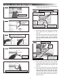
4. Carefully strip and prepare 120 Vac supply wire.
See (FIG. 21), (FIG. 22), (FIG. 23), (FIG. 24), &
(FIG. 25).
INSTALLATION INSTRUCTIONS

13
FIG. 21
Strip Jacket To 1″
FIG. 22
Hand Bend White
And Black Wires
Outward 90°
FIG. 23
Use Tip Of Pliers To Hold Wire In Place
While Hand Bending Wire At 90°
FIG. 24
Repeat With
Other Wire
FIG. 25
Trim Ground Wire To Length Of Outer Wires
5. Hold the clear strain relief cover with the bottom
facing upward. See (FIG. 26).
FIG. 26
Load Cable into Strain Relief
Wire Locator
Slots
Position Black Wire
Into Locator Slot
Strain Relief Cover
(Bottom Facing Upward)
Strain
Relief
Fingers
Roll Cable Sheath Into
Integral Strain Relief
6. Lay wire into locator slots, making sure the black
wire is placed into the polarization slot. See
(FIG. 26).
7. Press the cable sheath into the integral strain
relief slot. See (FIG. 26). Trimming of ground
wire and possibly others will be necessary.
Wires must not extend beyond the locators. See
(FIG. 27).
FIG. 27
Housing Assembly
Hinge
Slots
Strain Relief Cover
Wires Trimmed And
Correctly Located
In Locator Stops
Hinge
Posts
8. While holding the strain relief cover, position
the housing's hinge posts into the hinge slots
and press down until both lock into place. See
(FIG. 27).
9. Close the strain relief cover and housing by
hand. Squeeze the top and bottom closed with
tongue and groove pliers. See (FIG. 28). Pliers
mustbeaminimumof10″long.Squeezermly
on both sides, squarely across the connector
between ribs A and B to ensure wires seat com-
pletely into slots.
INSTALLATION INSTRUCTIONS

14
FIG. 28
Attaching Housing Assembly To Strain
Relief Cover With Tongue And Groove
Pliers, Squeeze Squarely & firmly
Between Ribs A & B
Strain Relief Cover 10″ Minimum
Rib A
Locking
Ramp
Locking
Latch
Rib B
Housing Assembly
10. Inspect the connector to ensure the wires have
been properly engaged into the housing assem-
bly contacts. A properly terminated wire is fully
seated into its proper slots with no signicant
bow of the cover. If the wires extend past the
insulation stops the wires must be re-terminated
with a NEW CONNECTOR. Once the cover has
been closed the connector cannot be re-used.
Failure to comply with this procedure may result
in the failure of the connector.
11. Mating and un-mating the completed connector
is illustrated below. See (FIG. 29).
FIG. 29
Housing
Assembly
Strain Relief
Cover
Depress Mating Latch
To Disconnect
To release the connector system, depress both mating
latches at the same time and pull the connectors apart.
To reconnect, simply re-mate the connectors and slide
them together until mating latches lock.
Strain Relief
Cover
Depress Mating
Latch To Disconnect
Housing
Assembly
"Hermaphroditic" Part Mates With Itself
J. Duct Divider Installation
1. Measure the ceiling thickness. See (FIG. 17).
2. Cut away the number of rows as indicated in
table below. See (FIG. 30).
Ceiling
Thickness
# Of
Rows
To Cut
Ceiling
Thickness
# Of
Rows
To Cut
Min. Max. Min Max.
6.0 6.5 0 3.5 4.0 5
5.5 6.0 1 3.0 3.5 6
5.0 5.5 2 2.5 3.0 7
4.5 5.0 3 2.0 2.5 8
4.0 4.5 4 1.5 2.0 9
FIG. 30
Remove Rows
Starting Here
3. Carefully install the duct divider in the roof
opening5-5/8″ from backofroofopening. See
(FIG. 31).
Foil back faces rear of unit.
FIG. 31
Rear
Base Pan
5-5/8″ From Back
Of Roof Opening
Duct Divider
Front
Black Side
To Front
K. LCD SZ System Low Voltage Wire
Connections
Make sure the positive (+) 12 Vdc
terminal is disconnected from supply battery. Oth-
erwise, damage to unit could occur.
1. Plastic Case Electronic Control Kit Systems
Only
a. Plug the supplied freeze control sensor and
the 4 wire harness into their matching con-
nectors in the electronic control box.
INSTALLATION INSTRUCTIONS

15
L. CCC 2 System Low Voltage Wire
Connections
Make sure the positive (+) 12 Vdc
terminal is disconnected from supply battery. Oth-
erwise, damage to unit could occur.
1. CCC 2 Electronic Control Kit Systems
a. Plug the 6 wire harness into the matching 6
pin connector in the electronic control box.
b. Plug the freeze control sensor into the P5
(Blue or Black) 2 pin matching connector in
the electronic control box.
c. Insert the freeze control sensor into the
evaporatorcoilnsapproximately1″above
the bottom of the coil ns and on the left
side.See(FIG.32).Bendnsoversensorto
secure in place.
2. All Heat Pump Electronic Control Kit Systems
a. Plug the outdoor temperature sensor from
the unit into the P3 (white) 2 pin matching
connector in the electronic control box.
b. Plug the 3 pin connector (reversing valve
wire) from the unit into the 3 pin matching
connector in the electronic control box.
3. All CCC 2 Systems
a. Connect the previously run 12 Vdc supply
wires to the red and black wires protruding
from the roof opening or the red and black
wires in the 6 wire harness at the electron-
ic control box. Connect +12 Vdc to the red
wire; –12 Vdc to the black wire.
b. Connect the previously run furnace thermo-
stat wires (if applicable) to the blue wires
protruding into the roof opening or the blue
wires in the 6 wire harness at the electronic
control box. The polarity of this connection
does not matter.
c. Terminate the 4 conductor communication
cable(s) protruding from the roof opening.
The cable(s) must be terminated with a tele-
phone RJ-11-6C4P connector. Refer to the
crimp tool manufacturer for crimping instruc-
tions.
RJ-11-6C4P connectors MUST be in-
stalled as shown in (FIG. 8) & (FIG. 9).
d. Plug the 4 conductor communication cable
into one of the couplers protruding from the
roof opening or in the electronic control box.
If more than one zone is used, the second
coupler is used to join each additional zone.
2. All Heat Pump Electronic Control Kit Systems
a. Plug the outdoor temperature sensor from
the unit into the white 2 pin matching con-
nector in the electronic control box.
3. All LCD SZ Electronic Control Kit Systems
a. Insert the freeze control sensor into the
evaporator coil ns approximately 2″ to 3″
abovethebottomofthecoilnsandonthe
leftside.See(FIG.32).Bendnsoversen-
sor to secure in place.
FIG. 32
Route Up Through
Return Air Opening
Remove
Hang Tag
Freeze Control
Sensor
4. All LCD SZ Systems
a. Connect the previously run +12 Vdc supply
wire to the red wire protruding from the roof
opening or to the red wire at the electronic
control box.
b. Connect the previously run –12 Vdc supply
wire to both the black wire protruding from
the roof opening or to the black wire at the
electronic control box and to the wire of the
three wire cable that goes to the thermostat
12V– terminal.
c. Connect the previously run furnace thermo-
stat wires (if applicable) to the blue wires
protruding from the roof opening or to the
1/4″connectorsattheelectroniccontrolbox
usingthesupplied1/4″insulatedconnectors.
The polarity of this connection does not ma-
ter.
d. Connect the red/white wire protruding from
the roof opening or the red/white wire at the
electronic control box to the wire of the three
wire cable that goes to the thermostat 12V+
terminal.
e. Connect the orange wire protruding from the
roof opening or the orange wire at the elec-
tronic control box to the wire of the three wire
cable that goes to the thermostat COMMS
terminal.
INSTALLATION INSTRUCTIONS

16
Dip switches are in the "OFF" position
when shipped from the factory except
heat pump and factory installed heat strip
models. On these models the appropriate
dip switch, heat pump or heat strip, is in
the "ON" position from the factory.
To gain access to the dip switches on mod-
els with board built in, the out side plastic
shroud MUST be removed from the unit.
Next remove the electrical box cover. The
electrical box will be on the curb side of
the RV after installation. See (FIG. 33).
Installations using the electronic control
box the dip switches are visible through
the opening in the electronic control box.
See (FIG. 34).
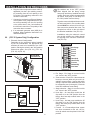
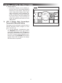
FIG. 35
Dip Switches
Zone 2
Ext. Stage
Zone 3
Zone 4
Stage
Heat Strip
Heat Pump
Furnace
Dehumidify
Gen Start
a. Ext. Stage - Ext. Stage is not used on this
unit. Leave in the "OFF" position.
b. Zone selection - Each CCC 2 thermostat can
have up to 4 zones. When only one unit is in-
stalled it becomes Zone 1 and no dip switch
setting is required. Each additional unit must
be assigned a zone (2 through 4). Each unit
musthaveadierentzonesetting.
c. Stage selection - Stage is not used on this
unit. Leave in the "OFF" position.
d. Heat Strip - On heat strip models the #6
dip switch is in the "ON" position from the
factory. Non heat strip models leave in the
"OFF" position.
e. Heat Pump - On heat pump models the #7
dip switch is in the "ON" position from the
factory. Non heat pump models leave in the
"OFF" position.
f. Furnace - If a Furnace/Aqua heat system
has been connected to this unit, the fur-
nace dip switch must be placed in the "ON"
position.
e. Plug the indoor temperature sensor cable (if
applicable) into the 2 pin matching connec-
tor protruding from the roof opening or the
P4 (white) 2 pin matching connector in the
electronic control box.
f. Connect the previously run Energy Manage-
ment System wires (if applicable) to the yel-
low wires protruding from the roof opening
or the yellow wires in the 6 wire harness at
the electronic control box. The polarity of this
connection does not matter.
g. If an automatic generator start (AGS) kit is
installed, follow installation instructions fur-
nished with AGS kit.
M. (CCC 2 System Only) Conguration
1. ElectronicControlConguration
Depending on the equipment options installed
by the RV manufacturer, the appropriate dip
switches will need to be switched to the "ON"
position. Placing the switch in the "ON" position
selects that option. See (FIG. 33), (FIG. 34),
(FIG. 35), & (FIG. 36).
FIG. 33
Models With
Board Built In
Dip Switches
FIG. 34
Dip
Switches
Models With Electronic Control Box
INSTALLATION INSTRUCTIONS

17
INSTALLATION INSTRUCTIONS
g. Dehumidify - Dehumidify is not used on this
unit. Leave in the "OFF" position.
h. Gen Start selection - Leave in the "OFF"
position.
i. Install unit electrical box cover and out side
plastic shroud or the electronic control box
cover whichever applies.
j. Repeat this procedure for each additional
zone.
FIG. 36
On Position
O Position
N. Installing Unit
1. If system includes an electronic control box in-
stall it at this time. Make sure all wiring has been
completed and that the electronic control box
cover has been installed. To secure electronic
control box to ceiling template drive two (2) #6
x3/8″(plasticcontrolbox)ortwo(2)#10x3/8″
(metal control box) blunt point Phillips head
screws (provided) through the ceiling template
and into holes in the electronic control box. See
(FIG. 37).
FIG. 37
Blunt Point
Screw
Ceiling
Template
Electronic
Control
Box
Metal Electronic
Control Box Shown
2. If your installation includes the optional electric
heat kit, install it at this time. Follow the instruc-
tions with heat kit package for its installation pro-
cedure.
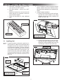
3. Ceiling Template Installation
a. Hold the ceiling template up to the roof open-
ing and line up the channel in the ceiling
template with the previously installed duct
divider. See (FIG. 38).
FIG. 38
Duct Divider
Channel
Model With Electronic
Control Box Shown
b. Hold the ceiling template up to the roof open-
ing and start each mounting bolt by hand,
through the ceiling template and up into the
unit base pan. See (FIG. 39) & (FIG. 40).
FIG. 39
Mounting Bolt
Mounting Bolt

18
Mounting Bolt Pattern Table
See (FIG. 40)
Model Bolt Location
457915 A, D, E & H
B57915 A, D, E & H
B57935U A, D, E & H
B57935Y A, D, E & H
459186 A, D, E & H
B59186 A, D, E & H
459196 A, D, E & H
B59196 A, D, E & H
459516 A, D, E & H
B59516 A, D, E & H
459530 A, D, E & H
B59530 A, D, E & H
B59536U A, D, E & H
B59536Y A, D, E & H
540315 B, C, F & G
540316 B, C, F & G
541815 B, C, F & G
Mounting Bolt Pattern Table
See (FIG. 40)
Model Bolt Location
541816 B, C, F & G
541915 B, C, F & G
541916 B, C, F & G
551816 B, C, F & G
551916 B, C, F & G
640310 B, C, F & G
640312 B, C, F & G
640315 B, C, F & G
641815 B, C, F & G
641816 B, C, F & G
641835 B, C, F & G
641915 B, C, F & G
641916 B, C, F & G
641935 B, C, F & G
651815 B, C, F & G
651816 B, C, F & G
651916 B, C, F & G
FIG. 40
A
HG
FE
D
C
B
c. Tighten mounting bolts to
correct torque specications. Overtighten-
ing could damage unit’s base pan or ceiling
template. Not enough torque will allow an in-
adequate roof seal, and could cause a leak.
d. Tighten all four (4) mounting bolts EVENLY
with in 40 to 50 inch pounds. See (FIG. 39).
O. Installing ADB
1. Align ADB with ceiling template. See (FIG. 41)
& (FIG. 42).
Front and rear vent doors are supplied
loose. Do NOT install them until all screws
are installed in step 2 & 3.
INSTALLATION INSTRUCTIONS
FIG. 41
ADB Alignment Holes
Ceiling Template
Alignment Holes
FIG. 42
ADB Hole
Alignment
Hole In Ceiling
Template
Hole In
ADB Cover

19
INSTALLATION INSTRUCTIONS
2. Install two (2) (supplied) sheet metal screws in-
side return air opening to secure ADB to ceiling
template. See (FIG. 43).
3. Install eight (8) (supplied) wood screws inside
the front, rear, and side doors to secure ADB to
ceiling. See (FIG. 43).
FIG. 43
2 Sheet
Metal Screws
8 Wood Screws
4. Install front and rear doors.
5. Place lterinto returnair vent grille.It mayal-
ready be installed on some units. See (FIG. 44).
FIG. 44
Filter
Return Air
Vent Grille
6. Install return air vent grille into the ADB. Slide re-
turn air vent grille tab into slot in ADB and rotate
up and snap in place. See (FIG. 45).
FIG. 45
Slot In ADB
Return Air
Vent Grille
This completes the LCD SZ system installa-
tion. (Proceed to section "P" to complete the
CCC 2 system installation).
7. (LCD SZ System Only) System Checkout
a. Verify that all features of the system work.
See the LCD SZ thermostat Operating In-
structions or User's Guide. Reconnect the 12
Vdc and 120 Vac power supplies. Check fan
speeds, cooling mode, heating mode, and
furnace mode (if connected) operation.
If features do not work, disconnect the 120
Vac and 12 Vdc power supplies and verify
that all wiring is correct.
P. (CCC 2 System Only) Reset & Checkout
1. System Reset
After setting the dip switches in the electronic
control, do a system reset.
a. Re-connect the 12 Vdc and 120 Vac power
supplies.
b. Make sure the CCC 2 thermostat is in the
OFF mode.
c. Simultaneously press the MODE and ZONE
buttons. The LCD will display "IniT" and all
available zones.
d. Release the MODE and ZONE buttons.
e. Press the ON/OFF button to exit system set
up.
f. When a dip switch is turned on after initial
conguration,asystemresetwillneedtobe
done before the CCC 2 thermostat will rec-
ognize the updated selection.

20
INSTALLATION INSTRUCTIONS
2. System Checkout
a. Verify that all features of the installed sys-
tem work. See CCC 2 thermostat Operating
Instructions or User's Guide. Check the fan
mode, cooling mode, heating mode (if appli-
cable), and furnace mode (if applicable) op-
eration. If features do not work, disconnect
the 120 Vac and 12 Vdc power supplies and
verify that all wiring is correct and that the
correct dip switches have been set to the
"ON" position.
Q. (CCC 2 System Only) Furnace/Aqua
Temperature Dierential Setting
Thissystemcanbeconguredtooperateusingan
ON//OFFdierentialofeither1degreeFor2de-
gree F. See (FIG. 46).
1. To set the dierential, simultaneously press
the PROGRAM button and the up button
on the CCC 2 thermostat. “diF1” will appear in
the display while the buttons are pressed. See
(FIG.46).Tosetthe2degreedierential,simul-
taneously press the PROGRAM button and the
down button “diF2” will appear in the display
while the buttons are pressed.
FIG. 46
Page is loading ...
Page is loading ...
Page is loading ...
Page is loading ...
Page is loading ...
-
 1
1
-
 2
2
-
 3
3
-
 4
4
-
 5
5
-
 6
6
-
 7
7
-
 8
8
-
 9
9
-
 10
10
-
 11
11
-
 12
12
-
 13
13
-
 14
14
-
 15
15
-
 16
16
-
 17
17
-
 18
18
-
 19
19
-
 20
20
-
 21
21
-
 22
22
-
 23
23
-
 24
24
-
 25
25


Dometic B57915.XX1C0 Installation guide
- Category
- Thermostats
- Type
- Installation guide
- This manual is also suitable for
Ask a question and I''ll find the answer in the document
Finding information in a document is now easier with AI
Related papers
-
Dometic Roof top AC 640312-640315_Use Installation guide
-
-
-
-
-
-
-
-
-
Dometic 600315.326 Operating instructions
Other documents
-
Voyager Advent Air Owner's manual
-
Inter-Tech 88885125 Datasheet
-
-
Black & Decker FSCP200 User manual
-
 RVP 6535 SERIES Installation Instructions Manual
-
Ideal 182S, 2-Wire Female Side, Carton of 1,000 Operating instructions
-
 Duo-Therm 3109228.001 Operating Instructions Manual
-
 Duo-Therm 3109228.001 Operating Instructions Manual
-
-


