
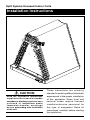
Split System Uncased Indoor Coils
Installation Instructions
CAUTION:
Read the Installation Instructions
supplied with furnace/air handler
and observe all safety r e q ui r e me n t s
o u t l i n e d i n instructions and/or
furnace/air handler markings
be fore proceeding with installation
of the coil.
These instructions are primarily
intended to assist qualified individuals
experienced in the proper installation
of this appliance. Some local and
national codes require licensed
installation/service personnel for
this type of equipment. Read all
instructions carefully before starting
the installation.

2

3
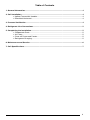
Table of Contents
1. General Information ................................................................................................................. 4
2. Coil Installation ........................................................................................................................ 4
.
Upflow Furnace/Air Handler ......................................................................................... 4
.
Downflow/Horizontal .................................................................................................... 4
3. Pressure Verification ............................................................................................................... 4
4. Refrigerant Line Connections ................................................................................................ 5
5. Completing the Installation..................................................................................................... 5
.
Condensate Drain ........................................................................................................ 5
.
Air Filters ..................................................................................................................... 5
.
Close-off Plates and Panels ......................................................................................... 5
.
Refrigerant Charging ................................................................................................... 5
6. Maintenance and Service ........................................................................................................ 6
7. Coil Specifications................................................................................................................... 7

4
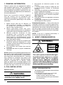
1. GENERAL INFORMATION
These C-series coils are designed for upflow
and downflow applications. They are equipped
with brazing stub refrigerant connections for
easy installation. Horizontal conversion kits are
available. Refer to the Specifications Table below
for more information.
Read the installation manual supplied
with the outdoor unit for refrigerant line
connection procedure, required line sizes,
and other information pertaining to the system
installation.
1. Make certain that the air delivery of
the furnace/air handler is adequate
to handle the static pressure drop of
the coil, filter, and duct work.
2. When applicable check the coil's
orifice size and confirm that it is suitable for
application with the intended outdoor unit.
3. Where precise forming of the
refrigerant lines is required, a copper
tubing bender designed for the size
lines used is recommended. Avoid
sharp bends and contact of the refrigerant
lines with metal surfaces.
4. Refrigerant lines should be wrapped with
pressure sensitive neoprene or other
suitable material where they pass through
the raw edges of holes.
5. Coil enclosure and suction line must be
insulated.
6. Coil must be level for proper condensate
drainage.
NOTE: Optional cooling/heating equipment must
be properly sized and installed in accordance
with the furnace manufacturer’s specifications
and approved recommendations. “Heating
only” furnace air circulators may have to be
replaced with multi-speed “Heating/Cooling”
blowers to upgrade the air delivery (CFM)
when an add-on coil is installed. Refer to Coil
Specifications for recommended CFM and allow
for pressure drop across the coil and filters.
2. COIL INSTALLATION
Upflow Furnace:
WARNING:
Electric furnaces may be connected to
more than one supply circuit.
1. Disconnect all electrical power to the
furnace.
2. If needed, make a plate to adapt the coil
to the furnace/air handler air discharge
opening.
3. Install the coil and level it as needed to allow
proper condensate drainage.
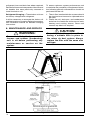
4. Make a plenum to enclose the coil or drop
the duct directly over it. Insulate as required.
(See Figure 2)
5. Seal the enclosure as required to minimize
air leakage.
6. Connect the refrigerant lines as outlined in
the Refrigerant Lines section.
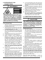
Downflow/Horizontal — These coils may be
installed in downflow or horizontal applications.
Installation of the coils in these applications only
requires that the coil be securely mounted and
that the proper horizontal drain kit be added.
Refer to the Specifications section for the proper
kit numbers.
NOTE: If the coil is installed horizontally, a
horizontal drain kit must be used.
3. VERIFY PRESSURIZATION
WARNING:
This coil is pressurized with Nitrogen.
Avoid direct face exposure or contact
with valve when gas is escaping.
Always ensure adequate ventilation
is present during the depressurization
process. Any uncertainties should be
addressed before proceeding.
VERIFY PRESSURIZATION:
- Test by depressing Schrader valve and listen
for escaping gas
- If no pressure is found, test coil for leak
- If no leak is found, install coil
- If leak is found, clearly mark leak
location and return coil to your distributor
for processing
NITROGEN
HEALTH
FLAMMABILITY
REACTIVITY
0 Minimal Hazard
1 Slight Hazard
1
0
0

5
4. REFRIGERANT LINE
CONNECTIONS
WARNING:
This coil is pressurized with Nitrogen.
Avoid direct face exposure or contact
with valve when gas is escaping.
Always ensure adequate ventilation
is present during the depressurization
process. Any uncertainties should be
addressed before proceeding.
Line Connections:
1. Remove the valve cap from the end of the
liquid line. Relieve all pressure from the coil
by depressing the valve.
2. Remove the valve core and valve core holder
on the liquid line. DO NOT reuse the valve,
threaded valve holder or O-ring.
3. It is recommended to wrap a wet rag around
the suction line between the sensing bulb
and the line set braze joint before applying
any heat.
4. Unbraze and remove the cap on the suction line.
5. Properly dispose of all removed parts.
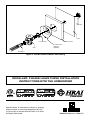
6. When included, install condensation
deflector and lock washer onto TXV.
Condensation deflector is to be installed
so that any condensation collecting on
the TXV is directed away from the cabinet
insulation and towards the drain pan. Fix
TXV into position using nut. See Figure 3.
Condensation deflector is not required if
TXV is not installed directly on cabinet.
7. Cut the line set tubing to the proper
length. Be sure that the tubing has been
sized in accordance with the outdoor unit
specifications.
8. Inspect both refrigerant lines. The ends
of the lines must be round, clean, and free
of any burrs.
9. Insert the suction line set tube into the coil
suction tube stub until it bottoms out.
10. Slip the nut from the schrader valve holder
onto the liquid line - check for correct
orientation. Insert liquid line into liquid line
stub until it bottoms out. Liquid line stub is
shipped with the coil, but is not attached.
11. It is recommended to wrap a wet rag around
the suction line between the sensing bulb
and the lineset braze joint before applying
any heat.
12. Braze the individual connections with dry
nitrogen flowing through the joint to eliminate
internal oxidation and scaling.
13. Fasten nut to secure the liquid line to the
bulkhead fitting. No O-Ring is required.
14. Check the assembly for leaks.
15. On horizontal applications of models with
TXV valve, re-position the sensing bulb on
the suction line so it is in the 4 o'clock or 8
o'clock position on the suction tube.
5. COMPLETING THE INSTALLATION
CAUTION:
The indoor coil must be checked to
ensure a level installation. Failure to do
so may result in improper condensate
disposal, causing structural damage,
premature equipment failure, or
possible personal injury.
Condensate Drain
—
1. The coil condensate pan is furnished with
3/4" NPSC drain connections. Use a PVC
or similar material fitting to attach the drain
line to the pan. The fitting should be only
hand tightened.
Overtightening may crack the drain pan
and create a condensate leak.
2. Connect the drain line and run to a suitable
drain avoiding sharp bends and pinching of
the line. Install a condensate trap and prime
with water.
3. During the system checkout, inspect the
drain line and connections to verify proper
condensate disposal.
4. Perform any necessary adjustments to the
coil components to ensure that all drip points
fall within the outline of the drain pan.
Air Filter — Air filters are not provided as an
integral part of this coil, however, a filter must
be installed upstream of the coil and inspected
frequently. When the filter becomes clogged with
dust or lint, it should be replaced (disposable type)
or cleaned (washable type). The filter should be
inspected and replaced or cleaned at least twice
during the year, generally at the start of each
heating and cooling season.
Close-Off Plates and Panels — Install the
necessary air close-off plates around the
NITROGEN
HEALTH
FLAMMABILITY
REACTIVITY
0 Minimal Hazard
1 Slight Hazard
1
0
0

6
19 1/2
W
2 1/2
HS
HL
3 1/8
Figure 1.
Figure 2.
refrigerant lines and drain line where required.
Reinstall all inner and outer panels of the furnace/
air handler that were previously removed to
install the indoor coil.
Refrigerant Charging — These indoor coils are
not factory charged with refrigerant.
It will be necessary to evacuate the indoor coil
and line set prior to charging. Refer to the outdoor
unit installation manual for detailed charging
instructions.
6. MAINTENANCE AND SERVICE
WARNING:
Ensure that all electrical power to the
furnace and outdoor (condensing)
unit is off before performing any
maintenance or service on the
system.
To ensure optimum system performance and
to minimize the possibility of equipment failure,
the following periodic maintenance should be
performed on the coil:
1. The air filter installed with the system should
be checked and cleaned or replaced twice
per year.
2. Check the coil, drain pan, and condensate
drain line for cleanliness at the start of each
heating and cooling season. Clean and
remove any debris as required.
CAUTION:
Do not operate the system without
having a suitable filter in place in
the return air duct system. Always
replace the filter with the same size
and type.

7
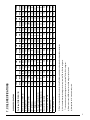
7. COIL SPECIFICATIONS
C6 COIL SPECIFICATIONS
Coil Model C6BA, C6BH (1)(2)
T24-A T30-A T24-B T30-B T36-B T42-B T36-C T42-C T48-C T60-C T42-D T48-D T60-D
X24-A X30-A X35-A X24-B X30-B X35-B X36-B X42-B X36-C X42-C X48-C X60-C X42-D X48-D X60-D
Nominal Capacity BTUH (3) 24,000 30,000 36,000 24,000 30,000 36,000 36,000 42,000 36,000 42,000 48,000 60,000 42,000 48,000 60,000
Metering Device TXV TXV TXV TXV TXV TXV TXV TXV TXV TXV TXV TXV TXV TXV TXV
Nominal Airflow (CFM) 800 1,000 1,000 800 1,000 1,200 1,200 1,400 1,200 1,400 1,600 2,000 1,400 1,600 2,000
W - Width (in.) 12 3/4 12 3/4 12 3/4 16 16 16 16 16 19 1/2 19 1/2 19 1/2 19 1/2 23 23 23
H - Height (in.) 1 9 1 9 19 19 19 19 24 3/4 24 3/4 23 3/4 23 3/4 28 3/4 28 3/4 24 28 1/4 28 1/4
HL - Height of Liquid Line (in.) 17 1/2 17 1/2 17 1/2 17 1/2 17 1/2 17 1/2 23 1/2 23 1/2 23 1/2 23 1/2 27 27 27 27 27
HS - Height of Suction Line (in.) 15 1/2 15 1/2 15 1/2 15 1/2 15 1/2 15 1/2 21 1/2 21 1/2 21 1/2 21 1/2 25 25 25 25 25
Connection - Liquid Line 3/8 3/8 3/8 3/8 3/8 3/8 3/8 3/8 3/8 3/8 3/8 3/8 3/8 3/8 3/8
Connection - Suction Line 3/4 3/4 3/4 3/4 3/4 3/4 7/8 7/8 7/8 7/8 7/8 7/8 7/8 7/8 7/8
Metering Device TXV TXV TXV TXV TXV TXV TXV TXV TXV TXV TXV TXV TXV TXV TXV
Horizontal Drain Kit (4) 920265 920265 920265 920265 920265 920265 920266 920266 920266 920266 920267 920267 920267 920267 920267
(1) Refer to sales specification sheets for Listed/Certified combinations of equipment and required accessories.
(2) X in the model description designates factory installed TXV for R-410a refrigerant.
T in the model description designates factory installed TXV for R-22 refrigerant.
(3) Refer to the current ARI Directory for certified ratings of split systems.
(4) Not required for "H" horizontal ready coils.

INSTALLER: PLEASE LEAVE THESE INSTALLATION
INSTRUCTIONS WITH THE HOMEOWNER
TXV
Lock Washer
Condensation
Deflector
(690071)
Insulation
Case
Nut
(606287)
Distributor
Figure 3. Condensation Deflector Positioning
708821D (Replaces 708821C)
Specifications & illustrations subject to change
without notice or incurring obligations (07/15).
O’Fallon, MO, © Nortek Global HVAC LLC 2015.
All Rights Reserved.
-
 1
1
-
 2
2
-
 3
3
-
 4
4
-
 5
5
-
 6
6
-
 7
7
-
 8
8


Ask a question and I''ll find the answer in the document
Finding information in a document is now easier with AI
Related papers
-
Broan C6B(A,H)-T Installation guide
-
Broan JS6BD-K Installation guide
-
Broan C6B(A,H)-T Installation guide
-
-
-
Broan C6BH-E Installation guide
-
Broan C7B(A,H)M0 Installation guide
-
Broan C7B(A,H)MX Installation guide
-
-
Other documents
-
Intertherm B6BX Installation guide
-
 GEARVITA T42 Hard reset manual
-
Intertherm C3(D,Q)-0 Installation guide
-
Carrier CSPVA Installation guide
-
Carrier CVPVA User manual
-
 APR SUPPLY EVM4X Cased Cooling Only Evaporator Coil Multipoise User manual
-
Allied EC1P Installation guide
-
Johnson Controls AV*(C) Series User manual
-
Gibson GB5BW Installation guide
-
Trane 4NXCD063BC3HCA Installer's Manual

