
www.PTN-electronics.com
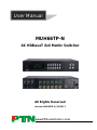
MUH66TP-N
4K HDBaseT 6x6 Matrix Switcher
All Rights Reserved
Version: MUH66TP-N_2015V1.1
User Manual

4K HDBaseT 6x6 Matrix Switcher
PTN Electronics Limited www.PTN-electronics.com
Preface
Read this user manual carefully before using this product. Pictures shown in this manual
is for reference only, different model and specifications are subject to real product.
This manual is only for operation instruction only, not for any maintenance usage. The
functions described in this version are updated till April 2015. Any changes of functions
and parameters since then will be informed separately. Please refer to the dealers for
the latest details.
All product function is valid till 2015-4-13.
Trademarks
Product model, PTN and its logo are trademarks of PTN Electronics Limited.
Any other trademarks mentioned in this manual are acknowledged as the properties of
the trademark owner. No part of this publication may be copied or reproduced without
the prior written consent of PTN Electronics Limited.
FCC Statement
This equipment generates, uses and can radiate radio frequency energy and, if not
installed and used in accordance with the instructions, may cause harmful interference
to radio communications. It has been tested and found to comply with the limits for a
Class B digital device, pursuant to part 15 of the FCC Rules. These limits are designed
to provide reasonable protection against harmful interference in a commercial
installation.
Operation of this equipment in a residential area is likely to cause interference, in which
case the user at their own expense will be required to take whatever measures may be
necessary to correct the interference
Any changes or modifications not expressly approved by the manufacture would void
the user’s authority to operate the equipment.

4K HDBaseT 6x6 Matrix Switcher
PTN Electronics Limited www.PTN-electronics.com
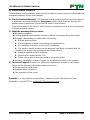
SAFETY PRECAUTIONS
To insure the best from the product, please read all instructions carefully before using
the device. Save this manual for further reference.
Unpack the equipment carefully and save the original box and packing material for
possible future shipment
Follow basic safety precautions to reduce the risk of fire, electrical shock and injury
to persons.
Do not dismantle the housing or modify the module. It may result in electrical shock
or burn.
Using supplies or parts not meeting the products’ specifications may cause damage,
deterioration or malfunction.
Refer all servicing to qualified service personnel.
To prevent fire or shock hazard, do not expose the unit to rain, moisture or install this
product near water.
Do not put any heavy items on the extension cable in case of extrusion.
Do not remove the housing of the device as opening or removing housing may
expose you to dangerous voltage or other hazards.
Install the device in a place with fine ventilation to avoid damage caused by
overheat.
Keep the module away from liquids.
Spillage into the housing may result in fire, electrical shock, or equipment damage. If
an object or liquid falls or spills on to the housing, unplug the module immediately.
Do not twist or pull by force ends of the optical cable. It can cause malfunction.
Do not use liquid or aerosol cleaners to clean this unit. Always unplug the power to
the device before cleaning.
Unplug the power cord when left unused for a long period of time.
Information on disposal for scrapped devices: do not burn or mix with general
household waste, please treat them as normal electrical wastes.

4K HDBaseT 6x6 Matrix Switcher
PTN Electronics Limited www.PTN-electronics.com
Contents
1. Introduction ................................................................................................................. 1
1.1 Introduction to the MUH66TP-N ........................................................................ 1
1.2 Features ............................................................................................................ 1
1.3 Package List ...................................................................................................... 1
2. Product Appearance of the MUH66TP-N .................................................................... 2
2.1 Front Panel ........................................................................................................ 2
2.2 Rear Panel ......................................................................................................... 3
3. System Connection ..................................................................................................... 5
3.1 System Applications .......................................................................................... 5
3.2 Usage Precautions ............................................................................................ 5
3.3 Connection Diagram .......................................................................................... 5
3.4 Connection Procedure ....................................................................................... 5
3.5 Connection with TPHD402PR ........................................................................... 6
4. System Operations ..................................................................................................... 7
4.1 Front Panel Button Control ................................................................................ 7
4.1.1 Switching I/O connection ......................................................................... 7
4.1.2 EDID Management .................................................................................. 8
4.1.3 Inquiry ...................................................................................................... 9
4.1.4 Clear operation ...................................................................................... 10
4.2 IR Control ........................................................................................................ 10
4.2.1 Usage of IR Remote .............................................................................. 11
4.2.2 IR Operations ........................................................................................ 12
4.3 RS232 Control ................................................................................................. 15
4.3.1 Connection with RS232 Communication Port ........................................ 15
4.3.2 Installation/uninstallation of RS232 Control Software ............................ 15
4.3.3 Basic Settings ........................................................................................ 15
4.3.4 RS232 Communication Commands ...................................................... 16
4.3.5 RS232 Control Modes ........................................................................... 24
4.3.6 Control 3rd-Party Device from Local ...................................................... 24
4.3.7 Bi-directional RS232 Control ................................................................. 25
4.4 TCP/IP Control................................................................................................. 26

4K HDBaseT 6x6 Matrix Switcher
PTN Electronics Limited www.PTN-electronics.com
4.4.1 Control Modes ....................................................................................... 26
4.4.2 GUI for TCP/IP control ........................................................................... 26
4.4.3 GUI Update............................................................................................ 30
4.5 Firmware Update via USB ............................................................................... 31
5. Specification ............................................................................................................. 32
6. Panel Drawing .......................................................................................................... 33
7. Troubleshooting & Maintenance ............................................................................... 34
8. After-sales Service .................................................................................................... 36

4K HDBaseT 6x6 Matrix Switcher
PTN Electronics Limited 1 www.PTN-electronics.com
1. Introduction
1.1 Introduction to the MUH66TP-N
MUH66TP-N is a professional 6x6 HDBaseT Matrix Switcher that accommodates 6
HDMI IN (4k signal at max), 6 auxiliary audio IN, 6 IR IN.
Select HDMI input by front panel buttons, IR, RS232, or GUI. The selected source is
delivered to HDMI Output 1~3 (for HDMI input 1~3) & HDBaseT outputs 1~6 (easy
extension to 70m at 1080p and 40m at 4Kx2K on a single CAT5e/6 connection with
HDBaseT receivers, with PoC) simultaneously. The unit also supports EDID
management and HDCP.
Except embedded HDMI audio, MUH66TP-N provides 6 auxiliary audio outputs. Audio
source is selectable via RS232 command. Selected audio is output via HDMI outputs&
HDBaseT outputs and the audio output sockets.
The unit also supports bi-directional RS232& IR control.
1.2 Features
Support HDMI 1.4, 4Kx2K& 1080p 3D
HDCP1.4 compatible, support manual HDCP management and auto-detecting
Transmit 4Kx2K signal for 8m via HDMI port, 40m via HDBT port
Audio source selectable via RS232 command
6 HDBaseT outputs, for easy extension to 70m at 1080p and 40m at 4Kx2K on a
single CAT5e/6 cable
Support PoC
LCD screen shows real-time I/O connection status, switching status, HDCP status,
and output resolution.
Controllable via front panel, RS232, IR and TCP/IP
Support bi-directional IR& RS232 control
Built-in GUI for TCP/IP control
Powerful EDID management
Support off memory for reliable operation
Support firmware upgrade through Micro USB port
Easy installation with rack-mounting design
1.3 Package List
1 x MUH66TP-N
2 x Mounting ears (6 x Screws)

4K HDBaseT 6x6 Matrix Switcher
PTN Electronics Limited 2 www.PTN-electronics.com
1 x RS232 cable
1 x IR Receiver
4 x Plastic cushions (4 x Black Screws)
1 x IR remote
1 x Power cord
18 x Pluggable Terminal Blocks
1 x User manual
Notes: Confirm if the product and the accessories are all included, if not, please
contact with the dealers.
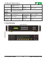
2. Product Appearance of the MUH66TP-N
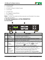
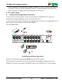
2.1 Front Panel
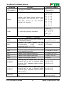
No.
Name
Description
①
Firmware
Micro USB port for updating firmware
②
Power
Indicator
Illuminate red when power on
Illuminate yellow in standby mode
③
IR
In-built IR sensor, receive IR signals sent from IR remote.
④
LCD Screen
Display real-time operation status.
⑤
INPUTS/
Menu
buttons
Normal mode: Back-lit buttons, ranging from "1" to "6".
Inquiry mode (buttons 1~4): Press ―ENTER‖ for more than
3 seconds to enter this mode. Dial to select
different menus, to select different options.
⑥
OUTPUTS
buttons/
EDID
Manageme
nt buttons
Normal mode: Back-lit buttons, ranging from "1" to "6".
Output 1~3 support synchronous local HDMI output.
EDID Invoking mode: press and hold EDID button for 3
seconds or more to enter this mode, buttons 1~6
correspond to the 6 embedded EDID data separately.
Press any of the 6 buttons to invoke embedded EDID data.
SYS TEM MON ITOR
CLEAR
ALL
OUTPUTS
INPUTS
MENU
2
3
4
5
6
ENTER
FIR MWARE
EDID
IR
1

4K HDBaseT 6x6 Matrix Switcher
PTN Electronics Limited 3 www.PTN-electronics.com
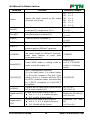
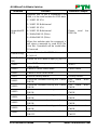
⑦
Function
buttons
ALL: Select all inputs/ outputs
Example: To transfer both AV and IR signals from input
channel No.1 to all output channels.
Operation: Press buttons in this order: ―1‖, ―ALL‖, ―ENTER‖
EDID management button: Enable input port to manually
capture and learn the EDID data of output devices.
Example: Input channel No.2 captures and learns the EDID
data of output channel No.4
Operation: Press buttons in this order: ―EDID‖, ―2‖, ―4‖,
―ENTER‖
CLEAR: Withdraw an operation like switching output
channel, learning EDID data before it comes into effect.
Meanwhile, the matrix will return to the previous status.
ENTER: Confirm operation. Press and hold it for 3 seconds
to enter in Inquiry mode.
Notes: Pictures shown in this manual are for reference only, different model and
specifications are subject to real product.
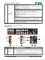
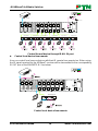
2.2 Rear Panel
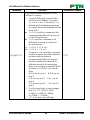
No.
Name
Description
①
INPUTS
a. IR OUT: 6 in total, connect with IR emitters to deliver the
IR signal sent from the far-end receivers connected to the
HDBaseT ports.
These IR OUT sockets make up an IR matrix with the IR
IN sockets on the far-end receivers, and all can be
RS2 32TCP /IP
IR ALL I N
IR EY E
L R
HDB aseT
RS23 2 AUDI O
OUT PUT 1
Tx Rx
HDM I
1
L R
HDB aseT
RS23 2 AUDI O
OUT PUT 2
Tx Rx
HDM I
2
L R
HDB aseT
RS23 2 AUDI O
OUT PUT 3
Tx Rx
HDM I
3
L R
HDB aseT
RS23 2 AUDI O
OUT PUT 4
Tx Rx
4
L R
HDB aseT
RS23 2 AUDI O
OUT PUT 5
Tx Rx
5
L R
HDB aseT
RS23 2 AUDI O
OUT PUT 6
Tx Rx
6
IR INIR INIR INIR INIR INIR IN
HDM I 6 HDM I 5
5
IR OU T
INP UT
AUDI O
5
L R
L R
6
6
HDM I 4 HDM I 3
3
IR OU T
INP UT
AUDI O
3
L R
L R
4
4
HDM I 2 HDM I 1
1
IR OU T
INP UT
AUDI O
1
L R
L R
2
2
Matrix
4K
RS232TCP/IP
IR ALL IN
IR EYE
HDMI 2 HDMI 1
1
IR OUT
INPUT
AUDIO
1
L R
L R
2
2
L R
HDBaseT
RS232 AUDIO
OUTPUT 1
Tx Rx
HDMI
1
IR IN

4K HDBaseT 6x6 Matrix Switcher
PTN Electronics Limited 4 www.PTN-electronics.com
switched synchronously with the AV signal, or separately
switching.
In default setting, the 6 IR OUT corresponds with the 6 IR
IN, i.e. IR OUT1→IR IN1, IR OUT2→IR IN2, …IR OUT6
→IR IN6.
b. AUDIO: Auxiliary audio input ports, 6 in total, connect with
analog audio sources
c. HDMI: HDMI input ports,6 in total, type A female HDMI
connector, connect with HDMI input source devices.
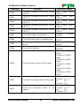
②
OUTPUTS
d. IR IN: Connect with IR receiver (with carrier), 6 in total,
correspond to the 6 IR OUT, cannot be switched
separately. It makes up an IR bi-directional transmission
with the IR OUT on the corresponding far-end receiver.
e. RS232: 3-pin pluggable terminal blocks, 6 in total,
correspond to 6 output sources separately, communicate
with the RS232 port on corresponding HDBaseT receiver,
cannot be switched separately. When controlled by
HDBaseT receiver, the communication protocol must be
the same with the MUH66TP-N’s.
f. AUDIO: stereo audio output ports, 6 in total
g. HDMI: Local HDMI output ports for HDMI Inputs 1~3,
synchronously switched with HDBaseT Output 1~3
h. HDBaseT: output extension ports, works with HDBaseT
receivers to extend signals and energize far-end
HDBaseT receiver on a single CAT5e/6 cable.
③
RS232
Serial port for unit control, 9-pin female connector, connects
with control device such as a PC.
④
IR Control
IR ALL IN: Input port for IR control signal, connect with IR
receiver (with carrier), delivers the received IR signal to all the
6 far-end receivers.
IR EYE: Connect with extended IR receiver, use the IR remote
to control the MUH66TP-N.
⑤
TCP/IP
TCP/IP port for unit control
⑥
GROUND
Connect to grounding, make the unit ground well.
⑦
Power
Power Trigger: Press the button to turn on/off the matrix. The
indicator turns red when power on.
Power port: Connect to an AC 100V~240V power adapter via
the included power cord
Note: Pictures shown in this manual are for reference only, different model and
specifications are subject to real product.

4K HDBaseT 6x6 Matrix Switcher
PTN Electronics Limited 5 www.PTN-electronics.com
3. System Connection
3.1 System Applications
As its good performance in control and transmission, the MUH66TP-N can be widely
used in computer realm, monitoring, large screen displaying, conference system,
television education and bank securities institutions etc.
3.2 Usage Precautions
1) System should be installed in a clean environment and has a prop temperature and
humidity.
2) All of the power switches, plugs, sockets and power cords should be insulated and
safe.
3) All devices should be connected before power on.
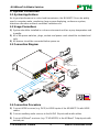
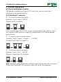
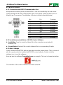
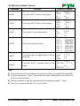
3.3 Connection Diagram
3.4 Connection Procedure
1) Connect HDMI sources (e.g. DVD) to HDMI inputs of the MUH66TP-N with HDMI
cables.
2) Connect auxiliary audio sources to the AUDIO IN ports with audio cables.
3) Connect HDBaseT receivers (e.g. TPHD402PR) to the HDBaseT Output ports with
twisted pair.
TPHD402PR
VCR
DVD
Laptop
HDTV
PoC
Speaker
IR Transmitter
RS232
PTN Control Panel

4K HDBaseT 6x6 Matrix Switcher
PTN Electronics Limited 6 www.PTN-electronics.com
4) Connect HDMI displays (e.g. HDTV) to HDMI outputs of the MUH66TP-N or the
receivers with HDMI cables
5) Connect speakers/earphones to AUDIO output ports
6) Connect the RS232 port of control device (e.g. a PC) to the RS232 port of either
MUH66TP-N or far-end receivers. RS232 signal can be transmitted bi-directionally
between MUH66TP-N and far-end receivers.
7) MUH66TP-N can collect IR signal sent by the included IR remote via its built-in IR
sensor or through external IR receiver connected to the IR IN/ IR EYE/ IR ALL IN
port. The IR signal can be transmitted bi-directionally between MUH66TP-N and
far-end receivers.
8) Connect an AC 100V~240V power outlet and the MUH66TP-N with the AC power
cord.
Note:
1. Connect HDBT ports of MUH66TP-N and far-end receiver with straight-through
cable.
2. Output audio is selectable via RS232 command Audio/[X]:[Y]. It’s free to select
whether analog audio or HDMI audio to output. Default is HDMI audio.
3. IR receivers connected to IR IN& IR ALL IN should be with carrier. If not, send
command %0900. or %0901.to activate native carrier mode or force carrier mode in
the IR matrix launched between MUH66TP-N and far-end receivers.
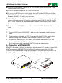
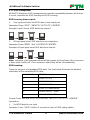
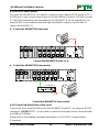
3.5 Connection with TPHD402PR
MUH66TP-N boasts 6 HDBaseT output ports which support PoC solution. Connect the
HDBT output ports of MUH66TP-N to HDBaseT Receivers supporting PoC (like
TPHD402PR) via twisted pair. Plug a power supply to the power port of MUH66TP-N,
the HDBaseT Receivers will be energized synchronously with PoC solution.
P
o
C
1
0
0
V
~
2
4
0
V
A
C
TPHD402PR

4K HDBaseT 6x6 Matrix Switcher
PTN Electronics Limited 7 www.PTN-electronics.com
4. System Operations
4.1 Front Panel Button Control
The operation examples are showed in 2.1 Front Panel. Here we make a brief
introduction to the system operations.
4.1.1 Switching I/O connection
1) To convert one input to an output:
Operation: ―input‖+―output‖+―ENTER‖
Example: input 1 to output 2
Note: In default status, the 6 IR OUT sockets correspond with 6 HDMI INPUTS. When
you convert an HDMI input to an output, the corresponding IR OUT will be switched
synchronously.
2) To convert an input to several outputs:
Operation: ―input‖ + ―output‖ + ―output‖ +… + ―ENTER‖
Example: Switch input 2 to output 2, 4
3) To convert an input to all outputs:
Operation: ―input‖ + ―ALL‖ + ―ENTER‖
Example: Convert input 1 to all outputs
Note: Indicators of the pressed buttons will blink green for three times if the conversion
is done, then it will be off. If the conversion failed, they will be off immediately.

4K HDBaseT 6x6 Matrix Switcher
PTN Electronics Limited 8 www.PTN-electronics.com
4.1.2 EDID Management
MUH66TP-N features EDID management to maintain compatibility between all devices.
It can be controlled via EDID learning and EDID invoking.
EDID Learning (from output):
One input port learns the EDID data of one output port
Operation: Press ―EDID‖, ―INPUTS‖+―OUTPUTS‖+―ENTER‖.
Example: Input 2 learns EDID data from output 4
All input ports learn EDID data from one output port
Operation: Press ―EDID‖, ―ALL‖+―OUTPUTS‖+―ENTER‖
Example: All input ports learn EDID data from output 4
Note: Indicators of the pressed buttons will blink green for three times if the conversion
is done, then it will be off. If the conversion failed, they will be off immediately.
EDID invoking:
There are six types of embedded EDID data. The chart below illustrates the detailed
information of the embedded EDID data:
Output Button
EDID Data
1
1080P 3D 2CH
2
1080P 3D Multichannel
3
1080P 2D 2CH
4
1080P 2D Multichannel
5
3840x2160 2D(30Hz)
6
4096x2160 2D(30Hz)
Format: Press and hold ―EDID‖ for 3 seconds, ―INPUTS‖+―OUTPUTS‖+―ENTER‖.
Operations:
Set EDID data for one input
Operation: Press ―EDID‖ (hold for 3 seconds to enter in EDID setting status),

4K HDBaseT 6x6 Matrix Switcher
PTN Electronics Limited 9 www.PTN-electronics.com
―INPUTS‖+―OUTPUTS‖+―ENTER‖.
Example: Set the EDID data of INPUT 4 to the forth type of embedded EDID data:
Press (hold for 3 seconds) .
Note: If the conversion is successful, indicators of the pressed buttons will blink green
for three times at normal speed; if the conversion failed, they will blink for three times
quickly.
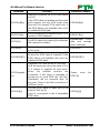
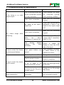
4.1.3 Inquiry
Check status
Press and hold the button ―ENTER‖ for 3 seconds, it will enter into system inquiry menu.
Use Left and Right direction button to navigate checking the previous/next items.
Function Items
Example
Description
Check the
connection
status of inputs
Y means the corresponding port
is connected with input device, N
means not.
Check the
connection
status of outputs
Y means the corresponding port
is connected with output device,
N means not.
Correspondence
between inputs
and outputs
Shows the correspondence
between the 6 inputs and 6
outputs.
Check if the
input is with
HDCP
Y means the input signal is with
HDCP, N means not.
Check if the
output is with
HDCP
Y means the output signal is with
HDCP, N means not.
Check the
output resolution
Use button to check the 6
output resolutions separately.
Output check
Press any output button to check its corresponding input.

4K HDBaseT 6x6 Matrix Switcher
PTN Electronics Limited 10 www.PTN-electronics.com
Example: Check which one is the corresponding input for output 2. (Presume Output 2
corresponds to Input 1.)
Operation: Press Output 2 button, LCD screen display ―AV: 1->2 IR: 1->2‖, and
indicators of input 1 and output 2 turn on and last for 3 seconds. Then output 2
corresponds to input 1.
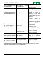
4.1.4 Clear operation
When you switch output channel, learn EDID data, or set EDID data, press Clear button
to withdraw the operation before you press ―ENTER‖ to carry it on. When you press it,
the matrix will return to the previous status.
4.2 IR Control
By using IR & HDBaseT transmission technology, the MUH66TP-N has some functions
as follows:
1) Control far-end output device from local.
2) Control local input/output device remotely.
3) Control the MUH66TP-N locally/remotely.

4K HDBaseT 6x6 Matrix Switcher
PTN Electronics Limited 11 www.PTN-electronics.com
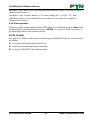
4.2.1 Usage of IR Remote
① Standby button, press it to enter/ exit standby
mode
② Input channels, range from 1~6 (buttons 7, 8
are not available), corresponding IR signal
switched synchronously when switching input
channels.
③ Menu buttons, ALL, EDID and CLEAR, same
with the corresponding front panel buttons.
Please refer to 4.1 Front Panel Button Control
for details.
④ : Navigation buttons.
ENTER: Confirm button.
⑤ Output channels, range from 1~6 (buttons 7,
8 are not available).
Each channel has 1 IR IN, 1 HDBaseT, 1
RS232, and 1 AUDIO outputs, and channel
1~3 have HDMI outputs.
Note: With this IR remote, MUH66TP-N can be controlled by the built-in IR, the
extended IR receiver connected to the ―IR EYE‖/‖IR ALL IN‖ and the IR receiver on the
far-end receiver.

4K HDBaseT 6x6 Matrix Switcher
PTN Electronics Limited 12 www.PTN-electronics.com
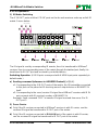
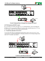
4.2.2 IR Operations
1) IR Matrix Switching
The 6 ―IR OUT‖ ports and the 6 ―IR IN‖ ports on the far-end receivers make up an 6x6 IR
matrix. See as below:
IR Matrix
The IR signal is sent by corresponding IR remote, then it is transferred to HDBaseT
receiver, then to corresponding zone of the matrix through the twisted pair, finally it is
transferred to IR OUT port and received by controlled device.
Switching Operation: (6 IR IN ports correspond with 6 HDMI input ports separately in
default mode.)
a) Sending command (reference to 4.3 RS232 Control): [x1]R[x2].
x1: Corresponding to the 6 IR OUT ports of the matrix, the IR transmitter connected
to this port can be placed at IR receiving area of output device or MUH66TP-N
itself.
x2: Corresponding to the zone (receive IR signal from HDBaseT receiver with IR IN
port connects with IR receiver) number of MUH66TP-N.
Example: Send command ―3R2.‖ to transfer IR signal received from zone 2 to IR
OUT port 3.
2) Force Carrier
a) Only if the IR receiver connected to HDBaseT receiver is with IR carrier, can the
received IR signal be transferred to IR OUT port of the matrix.
b) Only if the IR receiver connected to IR ALL IN port of the matrix is with IR carrier,
can the received IR signal be transferred to IR OUT port of the matrix.
IR Transmitter
HDM I 6
HDM I 4
HDM I 2
HDM I 5
HDM I 3
HDM I 1
5 63 41 2
5 63 41 2
RS23 2 AUDIO RS23 2 AUDIO RS232 AUDI O RS23 2 AUDI O RS23 2 AUDIO RS232 AUDI OAUDI OAUDI OAUD IO
L R
Tx Rx
L R
Tx Rx
L R
Tx Rx
L R
Tx Rx
L R
Tx Rx
L R
Tx Rx
L R
L R
L R
L R
L R
L R
HDM I
HDM I
HDM I
HDB aseT
HDB aseT
HDB aseT
HDB aseT
HDB aseT
HDB aseT
1 2 3 4 5 6
IR INIR INIR INIR INIR INIR IN
IR OU TI R OUTIR OU T
OUT PUT 1 OUT PUT 2 OUT PUT 3 OUT PUT 4 OU TPUT 5 OU TPUT 6
INP UTINP UTINP UT
RS2 32TCP /IP
IR ALL IN
IR EY E
Matrix
4K
Tx Rx
RS23 2IR IN IR OUT
24V
HDMI O UTHDBT I N
PoC
Tx Rx
RS23 2IR IN IR OUT
24V
HDMI O UTHDBT I N
PoC
Tx Rx
RS23 2IR IN IR OUT
24V
HDMI O UTHDB T IN
PoC
Tx Rx
RS23 2IR IN IR OUT
24V
HDMI O UTHDBT I N
PoC
Tx Rx
RS23 2IR IN IR OUT
24V
HDMI O UTHDBT I N
PoC
Tx Rx
RS23 2IR IN IR OUT
24V
HDMI O UTHDBT I N
PoC
TPHD402PR 1
TPHD402PR 2
TPHD402PR 3
TPHD402PR 4
TPHD402PR 5
TPHD402PR 6

4K HDBaseT 6x6 Matrix Switcher
PTN Electronics Limited 13 www.PTN-electronics.com
If the IR receiver connected with HDBaseT receiver or IR ALL IN port of the matrix is
not with IR carrier, send the command ―%0901.‖ to enter infrared carrier enforcing
mode, and then IR signal can be transferred to IR OUT port.
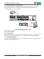
3) IR control setting
Control far-end output device from local
Connect an IR receiver with IR carrier to the IR IN port of MUH66TP-N, users can
control far-end output displayer via its IR remote from local.
In that case, the IR signal is transferred via twisted pair. Only the corresponding IR OUT
port can emit control signals to the remote display.
See the figure below:
Control far-end device from Local
Note: The IR receiver connected to IR IN must be with IR carrier
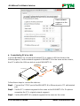
The IR signal received from IR ALL IN port will be transmitted to all the six far-end
HDBaseT receivers connected to HDBaseT ports of the MUH66TP-N. See as below:
DVD
HDTV
Tx Rx
RS2 32IR IN IR OUT
24V
HDMI OUTHDBT IN
PoC
TPHD402PR
IR Remote
HDTV
HDM I 6
HDM I 4
HDM I 2
HDM I 5
HDM I 3
HDM I 1
5 63 41 2
5 63 41 2
RS2 32 AUD IO R S232 A UDIO RS23 2 AUDI O RS 232 A UDIO RS23 2 AUDI O RS 232 AU DIOAUD IOAUD IOAUD IO
L R
Tx Rx
L R
Tx Rx
L R
Tx Rx
L R
Tx Rx
L R
Tx Rx
L R
Tx Rx
L R
L R
L R
L R
L R
L R
HDM I
HDM I
HDM I
HDB aseT
HDB aseT
HDB aseT
HDB aseT
HDB aseT
HDB aseT
1 2 3 4 5 6
IR INIR INIR INIR INIR INIR IN
IR OU TIR O UTIR OUT
OUT PUT 1 O UTPUT 2 OUT PUT 3 O UTPUT 4 OUT PUT 5 O UTPUT 6INP UTINP UTINP UT
RS2 32
TCP /IP
IR ALL IN
IR EY E
Matrix
4K

4K HDBaseT 6x6 Matrix Switcher
PTN Electronics Limited 14 www.PTN-electronics.com
Control far-end device through IR ALL IN port
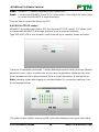
Control local device from remote
User can control local source devices with their IR remote from remote too. When using,
the IR signal received by the HDBaseT receiver will be transmitted to the corresponding
IR OUT port of the MUH66TP-N. See below:
Control local device from remote
HDM I 6
HDM I 4
HDM I 2
HDM I 5
HDM I 3
HDM I 1
5 63 41 2
5 63 41 2
RS23 2 AUDIO RS232 AUD IO R S232 AUD IO R S232 AUD IO R S232 AUD IO R S232 AUD IOAUDI OAUDI OAUDI O
L R
Tx R x
L R
Tx R x
L R
Tx R x
L R
Tx R x
L R
Tx R x
L R
Tx R x
L R
L R
L R
L R
L R
L R
HDM I
HDM I
HDM I
HDBa seT
HDBa seT
HDBa seT
HDBa seT
HDBa seT
HDBa seT
1 2 3 4 5 6
IR INIR INIR I NIR INIR INIR I NIR OUTIR O UTIR OUT
OUTP UT 1 OUTP UT 2 OUTP UT 3 OUTP UT 4 OUTP UT 5 OUTP UT 6INPU TINPUTIN PUT
RS2 32TCP /IP
IR ALL IN
IR EY E
Mat rix
4K
Tx Rx
RS23 2IR IN I R OUT
24V
HDMI O UTHDBT I N
PoC
Tx Rx
RS23 2IR IN I R OUT
24V
HDMI O UTHDBT I N
PoC
Tx Rx
RS23 2IR IN I R OUT
24V
HDMI O UTHDBT I N
PoC
Tx Rx
RS23 2IR IN I R OUT
24V
HDMI O UTHDBT I N
PoC
Tx Rx
RS23 2IR IN I R OUT
24V
HDMI O UTHDBT I N
PoC
Tx Rx
RS23 2IR IN I R OUT
24V
HDMI O UTHDBT I N
PoC
TPHD402PR 1
TPHD402PR 2
TPHD402PR 3
TPHD402PR 4
TPHD402PR 5
TPHD402PR 6
DVD
IR Remote
HDTV
HDTV
HDTV
HDTV
HDTV
HDTV
HDM I 6
HDM I 4
HDM I 2
HDM I 5
HDM I 3
HDM I 1
5 63 41 2
5 63 41 2
RS2 32 AUD IO RS23 2 AUDI O R S232 AUD IO RS232 AUD IO RS23 2 AUD IO RS232 AU DIOAUD IOAU DIOAUDIO
L R
Tx Rx
L R
Tx Rx
L R
Tx Rx
L R
Tx Rx
L R
Tx Rx
L R
Tx Rx
L R
L R
L R
L R
L R
L R
HDM I
HDM I
HDM I
HDB aseT
HDB aseT
HDB aseT
HDB aseT
HDB aseT
HDB aseT
1 2 3 4 5 6
IR INI R INIR INIR I NI R INIR INIR OU TIR OUTIR O UT
OUT PUT 1 OUTP UT 2 OUTP UT 3 O UTPUT 4 OU TPUT 5 OU TPUT 6
INP UTIN PUTI NPUT
RS2 32TCP /IP
IR ALL I N
IR EY E
Matri x
4K
Tx Rx
RS2 32IR IN IR OUT
24V
HDM I OUTHDB T IN
PoC
TPHD402PR
DVD
HDTV
HDTV
IR Remote

4K HDBaseT 6x6 Matrix Switcher
PTN Electronics Limited 15 www.PTN-electronics.com
4.3 RS232 Control
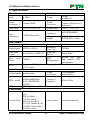
4.3.1 Connection with RS232 Communication Port
Except the front control panel, the MUH66TP-N can be controlled by far-end control
system through the RS232 communication port. This RS232 communication port is a
female 9-pin D connector. The definition of its pins is listed in the table below.
No. Pin Function
1 N/u Unused
2 Tx Transmit
3 Rx Receive
4 N/u Unused
5 Gnd Ground
6 N/u Unused
7 N/u Unused
8 N/u Unused
9 N/u Unused
4.3.2 Installation/uninstallation of RS232 Control Software
Installation Copy the control software file to the computer connected with
MUH66TP-N.
Uninstallation Delete all the control software files in corresponding file path.
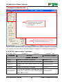
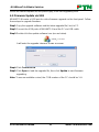
4.3.3 Basic Settings
Firstly, connect MUH66TP-N with an input device and an output device. Then, connect it
with a computer which is installed with RS232 control software. Double-click the
software icon to run this software.
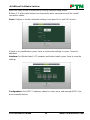
Here we take the software CommWatch.exe as example. The icon is showed as below:
The interface of the control software is showed as below:
Page is loading ...
Page is loading ...
Page is loading ...
Page is loading ...
Page is loading ...
Page is loading ...
Page is loading ...
Page is loading ...
Page is loading ...
Page is loading ...
Page is loading ...
Page is loading ...
Page is loading ...
Page is loading ...
Page is loading ...
Page is loading ...
Page is loading ...
Page is loading ...
Page is loading ...
Page is loading ...
Page is loading ...
Page is loading ...
Page is loading ...
Page is loading ...
-
 1
1
-
 2
2
-
 3
3
-
 4
4
-
 5
5
-
 6
6
-
 7
7
-
 8
8
-
 9
9
-
 10
10
-
 11
11
-
 12
12
-
 13
13
-
 14
14
-
 15
15
-
 16
16
-
 17
17
-
 18
18
-
 19
19
-
 20
20
-
 21
21
-
 22
22
-
 23
23
-
 24
24
-
 25
25
-
 26
26
-
 27
27
-
 28
28
-
 29
29
-
 30
30
-
 31
31
-
 32
32
-
 33
33
-
 34
34
-
 35
35
-
 36
36
-
 37
37
-
 38
38
-
 39
39
-
 40
40
-
 41
41
-
 42
42
-
 43
43
-
 44
44


Ask a question and I''ll find the answer in the document
Finding information in a document is now easier with AI
Related papers
Other documents
-
KanexPro FLEX-MMX32 User manual
-
ALFAtron MUH88E User manual
-
 PRO SIGNAL PSG3445 Operating instructions
-
 PRO SIGNAL PSG3446 Operating instructions
-
Vanco 4x3 HDBaseT Technical Support
-
AVGear AVG-MS88-HDBT User manual
-
DigitaLinx DL-RMKTC2H-W Installation guide
-
Polaris Big Bos 6x6 Owner's manual
-
-

