Page is loading ...

CONDENSING GAS FIRED
FLOOR OR WALL MOUNTED
BOILER
Manufactured by:
ECR International Inc.
2201 Dwyer Avenue, Utica, NY 13501
Tel. 800 325 5479
www.ecrinternational.com
PN 240011664 REV. L [11/01/2020]
Model
DMG-380
INSTALLATION, OPERATION &
MAINTENANCE MANUAL

2
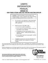
Fully Assembled Boiler Safety Relief Valve
Temperature Pressure
Gauge
Drain Valve
Used for measuring outside
temperature
Includes essential documents
Gas Shuto Valve Outdoor Sensor Document Package
Manifold (See page 13
5.8 for install instructions)
VERIFY CONTENTS RECEIVED
PN 240011664, Rev. L [11/01/2020]
For Parts lists see manual included with your boiler literature package.

3
TABLE OF CONTENTS
9.8 Before Gas Conversion .................................... 51
9.9 Gas Conversion (Propane) ...............................51
9.11 Combustion Setup (Low-Fire) ......................... 52
9.12 Operational Check .........................................52
9.10 Combustion Setup (High-Fire) ........................ 52
9.13 User Level Parameters ................................... 53
9.14 Installer Level Parameters .............................. 53
9.15 Parameters Settings ...................................... 54
9.16 Reading Measured Values .............................. 57
9.17 Status And Sub-Status .................................. 58
9.18 Return To The Factory Settings: ...................... 59
10 - Operating Instructions .................................... 60
10.1 Sequence Of Operation ..................................60
10.2 Operating Instructions ................................... 60
.......................... 60
11 - General Maintenance And Cleaning ................. 61
11.1 Beginning Of Each Heating Season .................. 61
11.2 Annual Shut Down Procedure ......................... 62
11.3 Annual Inspection And Cleaning Of Boiler Components 62
11.4 Maintenance And Routine Servicing ................. 63
11.5 Component Replacement And Cleaning ............ 63
11.6 Draining The Boiler .......................................64
12 - Ratings And Capacities .................................... 65
13 - Trouble Shooting ............................................. 66
13.1 Troubleshooting ............................................ 66
13.2 Shutdowns And Lock-Outs.............................. 68
13.3 Error History ................................................ 71
13.4 Error History Readout .................................... 71
13.5 Optional Sensors .......................................... 72
Troubleshooting Chart 1 ........................................73
Troubleshooting Chart 2 ........................................74
Troubleshooting Chart 3 ........................................75
Troubleshooting Chart 4 ........................................76
Troubleshooting Chart 5 ........................................77
Troubleshooting Chart 6 ........................................78
Troubleshooting Chart 7 ........................................79
Troubleshooting Chart 8 ........................................79
Troubleshooting Chart 9 ........................................80
Troubleshooting Chart 10 ...................................... 81
Troubleshooting Chart 11 ...................................... 82
Temperature-Resistance Chart ..............................83
14 - Glossary .......................................................... 84
1 - Important Information
........................................ 5
2 - Introduction ........................................................ 6
3 - Component Listing .............................................. 7
4 - Locating Boiler .................................................... 8
5 - Hydronic Piping ................................................. 10
5.1 General .........................................................10
5.2 Special Conditions .......................................... 10
5.3 Safety Relief Valve And Air Vent ........................ 11
.......................................... 11
5.5 Trim Piping .................................................... 12
5.6 System Piping ................................................ 12
5.7 Heating System And Refrigeration ..................... 13
5.8 Labor Savor Manifold Installation (Supplied) ...... 13
6 - Combustion Air And Vent Piping ........................ 17
6.1 General .........................................................17
6.2 Removal Of Existing Boiler From Common Vent System 17
..................................................... 18
6.4 Approved Venting Materials .............................. 19
6.5 Coaxial .......................................................... 19
6.6 Twin Pipe Polypropylene And Cpvc Systems ........ 21
6.7 Twin Pipe Spring Clamp Instructions ................. 21
....................................23
6.9 Side Venting Terminal Requirements ................ 27
6.10 Multiple Boiler Venting - General ................... 30
6.11 Multiple Boiler Venting - Mounting Procedure ... 30
6.12 Multiple Boiler Venting - Venting Layout ........... 32
6.13 Multiple Boiler Venting - Parameter Settings ..... 34
6.14 Condensate Piping ........................................ 35
7 - Gas Supply Piping ............................................. 36
7.1 General .........................................................36
7.2 Lp Conversion ................................................ 36
7.3 Leak Check Gas Piping .................................... 37
8 - Electrical Connections ....................................... 38
8.1 General .........................................................38
8.2 Electric Knockouts ......................................... 38
8.3 Electrical Connections ..................................... 38
8.4 Access To Connection Block .............................. 39
8.5 Main Supply Connection .................................. 39
8.6 Shutdown Input ............................................. 40
8.7 Release Input ................................................. 40
8.8 Optional Electrical Connections: ....................... 40
....... 43
8.10 Central Heating Thermostat ........................... 43
.................. 44
8.12 Frost Protection ............................................ 44
8.13 Pump Anti-Seize Protection ............................ 44
9 - Start Up Procedure ............................................ 47
9.1 Fill Condensate Trap With Water ....................... 47
9.2 Commission Setup (Water) .............................. 47
9.3 Commission Setup (Gas) ................................. 48
9.4 Commission Setup (Electric) ............................ 48
9.5 Control Panel..................................................49
9.6 Deaeration Function ........................................50
9.7 Commissioning ............................................... 51
PN 240011664, Rev. L [11/01/2020]

4
Table 1: Physical Data
Model
380
Width (A)
Height (B)
Depth (C)
Bottom Cabinet (D)
Access from Back or Sides of Jacket
Water
Connections
Size 1-½ (38.1mm)
Location (G)
Location (H)
Return
Location (I)
Supply
Gas
Connection
Location (L)
Size
Condensate Drain
Connection (J)
Location (J)
Size
Weight
Shipping 255 LBS (115.7)
Unit 225 LBS (102.1kg)
Vent Connector - Concentric
110/160 mm
Electrical Cord Length
5 ft. (1.5m)
PHYSICAL DATA
Dimensions
Vent Connector
Combustion
Air
A
B
Front View
Top View
Bottom View
Dimensions
H
G
C
J
Condensate Drain
Connection
Return Water
Gas Connection
Bottom View
Connection
Identication
Supply Water
50 psi safety relief valve (3.44 bar)
(22.2m)
Wire Knockouts
D
Front of Boiler
Front of Boiler
L
Front of Boiler
I
PN 240011664, Rev. L [11/01/2020]

5
1 - IMPORTANT INFORMATION
CAUTION
Indicates a hazardous situation which, if not avoided,
could result in minor or moderate injury.
!!
WARNING
Indicates a hazardous situation which, if not avoided,
could result in death or serious injury.
!
DANGER
Indicates a hazardous situation which, if not avoided,
WILL result in death or serious injury.
!
This is the safety alert symbol. Symbol alerts you
to potential personal injury hazards. Obey all safety
messages following this symbol to avoid possible injury or
death.
Become familiar with symbols identifying potential hazards.
glossary for additional information.
1. Safety Information
WARNING
Do not tamper with or use this boiler for any purpose
other than its intended use. Failure to follow these
instructions could result in death or serious injury.
Use only manufacturer recommended parts and
accessories.
!
CAUTION
Laceration, burn hazard. Metal edges and parts
may have sharp edges and/or may be hot. Use
appropriate personal protection equipment to include
safety glasses and gloves when installing or servicing
this boiler. Failure to follow these instructions could
result in minor or moderate injury.
!!
WARNING
Fire, explosion, asphyxiation and electrical shock
hazard. Improper installation could result in death or
serious injury. Read this manual and understand all
requirements before beginning installation.
!
FOR YOUR SAFETY READ BEFORE OPERATING
Hot Water Can Scald!
Water heated to temperature for clothes washing,
dish washing and other sanitizing needs can scald
and cause permanent injury.
persons are more likely to be permanently injured by
tap or draw their own bath.
above description, or if state laws or local codes
require certain water temperatures at hot water
taps, you must take special precautions:
• Use lowest possible temperature setting.
• Install some type of tempering device, such
as an automatic mixing valve, at hot water
tap or water heater. Automatic mixing valve
must be selected and installed according
to manufacturer's recommendations and
instructions.
• Water passing out of drain valves may be
extremely hot. To avoid injury:
• Make sure all connections are tight.
•
DANGER
!
Water
Temperature
Seng
1st Degree Burn
Exposure Time For
An Adult
2nd and 3rd Degree Burn
Exposure Time For An
Adult
120° F 1 minute 5 minutes
130° F 5 seconds 30 seconds
140° F 2 seconds 5 seconds
150° F 1 second 1.5 seconds
160° F Instantaneous 0.5 seconds
Note: Warning for Infants, Children, and Elderly: Great
care must be taken when exposing the aforementioned
groups to warm or hot water as they can be badly burned
in exposure times less than half of the time for an adult.
Note
Used to address practices not related to
personal injury.
WARNING
Fire, Explosion, Asphyxiation, Electrical shock hazard!
Flooding will result in damages such as electrical
problems, corrosion, inoperative parts, mold and
other unforeseen issues which can occur over time.
Any equipment determined by a professional as
other liquid, shall be replaced. Failure to follow these
directions will result in a Hazardous Situation.
!
PN 240011664, Rev. L [11/01/2020]

6
Check our website frequently for updates: www.ecrinternational.com
Information and specications outlined in this manual in eect at the
time of printing of this man ECR International reserves the right to
discontinue, change specications or system design at any time without
notice and without incurring any obligation, whatsoever.
2 - INTRODUCTION
2.5 Designated Use
• Hot water heating boiler.
• Indoor installation.
• Closet or alcove installation.
• Direct vent boiler or single vent pipe.
•
(LP/propane).
2.6 The unit MUST NOT:
• Directly heat potable water. Indirect heating is acceptable.
• Heat water with non-hydronic heating system chemicals
present (example, swimming pool water).
• Exceed 50 psig (3.44 bar) maximum allowable working
pressure, or drop below minimum system pressure 7.25
psig (.50 bar)
• Exceed 176°F (80°C) system design temperature.
2.7 Operational Features
• Modulating: 10:1 ratio.
• Integral Dual Limit.
•
• Outdoor Temperature Reset.
• Heat exchanger over heat protection.
• Recommended system pressure (cold) 21.7 psig (1.5
bar)
2.8 CSD-1 Compliance
Consult authority having jurisdiction prior to installation.
Field source:
•
• Manual Reset External High Temperature Limit.
2 - Introduction
2.1 Installation shall conform to requirements of authority
having jurisdiction or in absence of such requirements:
• United States
•
.
•
2.2 Where required by authority having jurisdiction,
installation shall conform to Standard for Controls and Safety
2.3 Requirements for Commonwealth of Massachusetts:
Boiler installation must conform to Commonwealth of
Massachusetts code 248 CMR which includes but is not limited
to:
2.4 Manufacturer recommends use of Carbon
Monoxide monitor may be requirement of local
jurisdiction.
PN 240011664, Rev. L [11/01/2020]

7
3 - COMPONENT LISTING
1 Condensate trap
2 Gas Valve
3 Fan
4 Air/gas mixer
5 Heat exchanger
6 Thermal fuse (#6 on wire diagram)
7
8 Exhaust test port
9 Intake test port
10 Flue sensor
11 Automatic air vent
12
wire diagram)
13 Burner sight glass
14 Ignition/Flame detection electrode
15 Spark generator
16 Auxiliary control board box
17 Air/gas venturi
18 Pump
19 Boiler drain
20 Low water pressure switch
A Condensate trap drain
B Gas inlet connection
C Heating supply connection
D Heating return connection
1
2
3
4
5
7
6
8
9
10
11
13
12
14
15
16
17
18
19
20
PN 240011664, Rev. L [11/01/2020]
DMG-380

8
4 - LOCATING BOILER
4.1 Boiler Location Considerations
• Ambient room temperature always above 32°F (0°C) to
prevent freezing of liquid condensate.
• Approved for installation in closets or alcove provided it
is correctly designed for that purpose.
•
• Protect gas ignition system components from water
(dripping, spraying, rain, etc.) during operation and
service (circulator replacement, condensate trap, control
replacement, etc.).
• Access to outdoors to meet minimum and maximum
pipe lengths for combustion air and vent piping. See
section 6.
• Disposal of condensate. See section 6.
• Drainage of water (or water - antifreeze solution) during
boiler service or from safety relief valve discharge. See
section 5.
• Access to system water piping, gas supply, and electrical
service. See sections 5, 7 and 8.
• Clearances to combustible materials and service
•
supporting the weight of the boiler.
• Do not install on carpet.
• Boiler may be installed in any room or internal space,
special attention shall be given to the requirements
of the current electrical provisions with respect to the
installation of the boiler in a room or internal space
containing a bath or shower. Where a room- sealed
boiler is installed in a room containing a bath or shower,
it must not be possible for a person using the bath or
shower to touch any electrical switch or boiler control
utilizing line voltage electricity.
• Multiple Boilers can be placed side by side, or back to
back.
TABLE 2: BOILER CLEARANCES
Dimension
Combustible
Materials
(1)
Service
(1)(2)
Model DMG - 380
Top (A)
15-3/4
(400 mm)
Left Side (B))
(45 mm)
(45 mm)
Right Side (C)
(45 mm)
(45 mm)
Front (D)
(45 mm)
(450 mm)
Back (E)
Bottom (F)
Combustion Air/Vent
piping
(1)
Required distances measured from boiler jacket.
(2)
Service, proper operation clearance recommendation.
* Allowance for piping at the bottom of boiler not included.
WARNING
Fire Hazard! Do not install on carpeting. Failure to
follow these instructions could result in death or
serious injury.
!
Note
piping can be damaged if subjected to excessive
torque.
PN 240011664, Rev. L [11/01/2020]

9
4 - LOCATING BOILER
A
E
E
D
A
CB
A
FLOOR
FLOOR
Boiler Front
View
Boiler Left Side View
FIGURE 4-1a Clearance to Combustible Materials FIGURE 4-2a Service Clearances - Boiler Front View
FIGURE 4-1b Clearance to Combustible Materials
FIGURE 4-2b Service Clearances - Boiler Left Side
View
Boiler
Front View
FIGURE 4-2c Combustible Clearances - Closet
Installation
Boiler Left
Side View
Minimum Service
clearance to front
of boiler
17 3/4 "
(
mm)
TOP VIEW
1 3/4 "
(
mm)
1 3/4 "
(
mm)
1 3/4 "
(
mm)
BACK
CLEARANCES REQUIRED FOR CLOSET
INSTALLATION
0 in. /0 mm between the Back of the Unit and the wall
(See Table 2, page 8)
(45mm)
(45mm)
(45mm)
(See Table 2, page 8)
PN 240011664, Rev. L [11/01/2020]

10
• It is necessary to semi-annually check the water quality
of central heating systems.
• Flush system to remove any solid objects such as metal
•
separately. If purge valves and isolation valves are not
installed, install them to properly clean the system.
• When purging installations that include standing iron
radiators and systems with manual vents at high points,
start with nearest manual air vent. Open the vent until
working toward furthest air vent.
• Install a basket strainer if large amounts of sediment is
present. Keep basket clear of sediment build up.
• Install a magnetic dirt separator in the hydronic system
where there are cast iron or steel components, or where
the previous boiler was a cast iron heat exchanger. The
and can deposit onto heat exchange surfaces and
and premature wear.
• Flush system until water runs clean and piping is free of
sediment.
• Manufacturer recommends a water treatment product
be used for sediment removal.
5.2 Special Conditions
Note
• System piping exposed to freezing conditions: Use
manufacturer for use with closed water heating system.
Do not use automotive or ethylene glycol.
• Boiler installed above radiation level (or as required
by authority having jurisdiction). Integral low water
pressure switch is provided in boiler.
• Boiler used in connection with refrigeration system.
Install piping in parallel with boiler, with appropriate
valves to prevent chilled medium from entering boiler.
• System piping connected to heating coils located in air
handling unit exposed to refrigerated air circulation.
prevent gravity circulation of boiler water during cooling
cycle.
5 - HYDRONIC PIPING
5.1 General
• Primary/Secondary piping required.
• Install piping in accordance with authority having
jurisdiction.
• Support system piping and safety relief valve discharge
piping. Boiler's internal piping and wall mount bracket
can be damaged if subjected to excessive weight.
• Size central heating pump (and domestic hot water
pump, if used) for system requirements only. Internal
heat exchanger pump compensates for pressure drop
through boiler internal piping and heat exchanger.
•
boiler.
• If oil is present in system water, use approved detergent
to wash system.
Note
Boiler rated at 80 psig (551.6 kPa) maximum
allowable working pressure. Boiler provided with
50 psig (345 kPa) safety relief valve. Field source
safety relief valves for system pressures greater
than 50 psig (345 kPa).
WARNING
• Poison hazard. Ethylene glycol is toxic. Do not
use ethylene glycol.
•
antifreeze, even ethylene glycol made for
hydronic systems.
• Ethylene glycol can attack gaskets and seals used
in hydronic systems.
• Do not use petroleum based cleaning or sealing
compounds boiler system.
•
water.
• Use only inhibited propylene glycol solutions
use with closed water heating system.
•
glycol before installing new Boiler.
• Provide user with Material Safety Data Sheet
!
Do not expose boiler and condensate piping to
freezing temperatures.
Note
When installing safety relief valve it must be
installed in a vertical position with spindle at top.
PN 240011664, Rev. L [11/01/2020]

11
WARNING
Burn and scald hazard. Safety relief valve could
discharge steam or hot water during operation.
Install discharge piping per these instructions.
!
FIGURE 5-1 Safety Relief Valve Discharge Piping
5 - HYDRONIC PIPING
5.3 Safety Relief Valve and Air Vent
•
• Install safety relief valve with spindle in vertical position.
•
relief valve.
• Install discharge piping from safety relief valve.
•
• Use pipe suitable for temperatures of 375°F (191°C) or
greater.
• Individual boiler discharge piping shall be independent
of other discharge piping.
• Size and arrange discharge piping to avoid reducing
safety relief valve relieving capacity below minimum
relief valve capacity stated on rating plate.
• Run pipe as short and straight as possible to location
protecting user from scalding and properly drain piping.
• Install union, if used, close to safety relief valve outlet.
• Install elbow(s), if used, close to safety relief valve
outlet and downstream of union (if used).
• Terminate pipe with plain end (not threaded).
Check Local Codes For Check Local Codes For
Maximum Distance To Maximum Distance To
FloorFloor
5.4 Low Water Cuto
• Boiler is equipped with Low Water Pressure Switch.
•
between boiler and LWCO probe..
• If using separate stand pipe, install air vent using tee to
avoid nuisance shutdowns.
• Arrange piping to prevent water dripping onto boiler.
• Connect probe signal wires to shutdown terminal (BL) on
control board, so it does not interfere with post purge.
WARNING
Fire, explosion hazard. Mount boiler vertically or
slightly tilted backward to insure proper function of
could result in death or serious injury.
!
Safety Relief Valve
FIGURE 5-2 System Piping - LWCO Probe Location
Viewed from Back of Boiler
System
Supply
ACCEPTABLE
HEIGHT FOR
LWCO PROBE
Check Local Codes
For Maximum
Distance To Floor
12” (305mm)
Maximum
Separation
System
Return
System
Supply
PN 240011664, Rev. L [11/01/2020]

12
WARNING
Burn and scald hazard. Primary/Secondary piping
with closely spaced supply and return lines is
mandatory for ASME Code Compliance. Failure to
follow these instructions could result in death or
serious injury.
!
Check Local Codes Check Local Codes
For Maximum For Maximum
Distance To FloorDistance To Floor
5.5 Trim Piping
• Temperature - Pressure Gauge. Install temperature
visible.
• Boiler has integral drain valve located inside jacket directly
underneath pump. Install provided external drain valve.
5.6 System Piping
•
•
be required by local authority having jurisdiction to have
•
for general
guidance. Additional considerations:
• Boiler control is designed for single central heating
pump. Installer responsible for integration of
multiple central heating pumps.
• Boiler control allows domestic hot water
prioritization. Function could be lost if central heating
pump not directly connected to control system.
• Multiple boiler system.
for general
guidance. Additional considerations:
• Control system requires equivalent water
temperatures entering each boiler to properly sequence
and adjust system supply temperature.
WARNING
Burn and scald hazard. Verify all plastic caps are
removed from boiler connections. Failure to follow
these instructions could result in death or serious
injury.
!
•
•
• Ensure washers supplied are utilized.
•
• Fit union connections to supply and return on boiler.
A. If soldering to boiler,
ensure unions are not connected
to the supply and return piping,
otherwise internal seals
may be damaged.
B.
C. Fit pressure relief valve connection vertically before
heating isolating valve.
• Connect system valve pipe work to the boiler.
FIGURE 5-3 Temperature Pressure Gauge and Safety
Relief Valve Installation - Viewed from Back of Boiler
5 - HYDRONIC PIPING
Safety Safety
Relief Relief
ValveValve
Temperature Temperature
Pressure Pressure
GaugeGauge
LWCOLWCO
System
Return
System
Supply
ACCEPTABLE
HEIGHT FOR
LWCO PROBE
12” (305mm)
Maximum
Separation
PN 240011664, Rev. L [11/01/2020]

13
WARNING
Burn and scald hazard. Safety relief valve could
discharge steam or hot water during operation.
Install discharge piping per these instructions.
!
•
Follow local code with respect to necessary distance to the
• Verify all valves are closed.
• Connect supplied condensate trap to a drain. Verify there is
continuous slope towards the drain, avoid level horizontal
sections of tubing.
5.7 Heating System And Refrigeration
Boiler when used in connection with refrigeration system,
must be installed so chilled medium is piped in parallel with
the boiler with appropriate valves to prevent chilled medium
from entering the boiler.
Boiler piping system of hot water boiler connected to heating
coils located in air handling units where they may be exposed
control valves or other automatic means to prevent gravity
circulation of the boiler water during the cooling cycle.
5 - HYDRONIC PIPING
5.8 Labor Savor Manifold Installation (supplied) See
Figure 5-3
1.
Boiler is supplied with union connection installed on boiler
piping for connection to manifold.
2.
Note
Identify BOILER supply and return when
installing manifold.
3.
Tighten manifold in place. Check for leaks.
PN 240011664, Rev. L [11/01/2020]

14
Table 4 - System Piping Congurations
Single Boiler
Primary/Secondary Pumping
Figure 5-4
Figure 5-5
Multiple Boilers
See Application Manual 240012832
5 - HYDRONIC PIPING
Note
Illustrations are meant to show system piping
concept only. Installer responsible for all
equipment and detailing required by authority
having jurisdiction.
Piping Legend
Boiler
WARNING
Burn, Scald Hazard! Water temperature over 125°F
(51°C) can cause severe burns and scalding. See
User's Manual before setting water temperature.
Failure to follow these instructions could result in
death or serious injury.
!
PN 240011664, Rev. L [11/01/2020]

15
5 - HYDRONIC PIPING
FIGURE 5-4 - Primary/Secondary, Zoned, WITH ZONE VALVES, (Optional) Indirect Tank
1
12” (305mm) Maximum
Separation required if Labor
Saver is NOT used.
Note
Note
* Manufacturer requires all domestic
hot water (DHW) installations use
an anti-scald valve. Local codes
may require additional equipment
(expansion tank, relief valves,
etc.) Select and size equipment
to suit installation and meet code
requirements.
T & P Relief
Valve to
Drain
Cold
Water
Supply
Optional
Indirect
DHW Tank
BOILER
Make-up
Water
Supply
Tank
Sensor
CH /System
Pump
ASME
Relief
Valve
1
DHW Pump
* Hot
Water
Supply
Tempered
S
Note
Refer to pump manufacturer
literature for proper pump sizing.
PN 240011664, Rev. L [11/01/2020]

16
5 - HYDRONIC PIPING
FIGURE 5-5 - Primary/Secondary, Zoned, WITH ZONE PUMPS, (Optional) Indirect Tank
T & P Relief
Valve to
Drain
Cold
Water
Supply
Optional
Indirect
DHW Tank
BOILER
Make-up
Water
Supply
Tank
Sensor
CH /System
Pump
ASME
Relief
Valve
1
DHW Pump
1
1
Note
Note
* Manufacturer requires all domestic
hot water (DHW) installations use
an anti-scald valve. Local codes
may require additional equipment
(expansion tank, relief valves,
etc.) Select and size equipment
to suit installation and meet code
requirements.
* Hot
Water
Supply
Tempered
S
Note
Control to interface system pump to boiler.
12” (305mm) Maximum
Separation required if Labor
Saver is NOT used.
Note
Refer to pump manufacturer
literature for proper pump sizing.
PN 240011664, Rev. L [11/01/2020]

17
6 - COMBUSTION AIR AND VENT PIPING
WARNING
Fire, explosion, and asphyxiation hazard. Improper
installation could result in death or serious
injury. Read these instructions and understand all
requirements before beginning installation.
!
•
•
• Assemble piping in accordance with pipe manufacturer's
instructions.
•
manufacturer's recommendation whichever is greater, back
toward the boiler.
• Support horizontal sections of vent pipe to prevent sags
capable of accumulating condensation. Unless otherwise
strapping or equivalent.
•
lubrication during assembly of vent pipe.
• Check for proper joint construction when joining pipe to
.
• Manufacturer requires use of an approved mechanical
fastener, which may vary per vent pipe manufacturer, at
every
polypropylene vent system.
WARNING
ABS/PVC venting shall not to be used this product.
Use of DWV plumbing pipes to vent this boiler shall
be prohibited.
Use of cellular core PVC (ASTM F891), cellular core
CPVC, or Radel® (polyphenolsulfone) in venting
systems shall be prohibited.
thermal insulation shall be prohibited.
Failure to follow these instructions could result in
death or serious injury.
!
Note
Follow venting manufacturer's equivalent lengths
for speciality ttings.
6.2 Removal of Existing Boiler From Common Vent
System
When existing boiler is removed from common venting
system, common venting system is likely to be too large for
proper venting of appliances remaining connected to it.
After removal of existing boiler, following steps shall be
followed with each appliance remaining connected to common
venting system placed in operation, while other appliances
remaining connected to common venting system are not in
operation:
• Seal any unused openings in common venting system.
• Visually inspect venting system for proper size and
horizontal pitch. Determine there is no blockage or
could cause an unsafe condition.
• When practical, close all building doors, windows, and
all doors between space in which appliances remaining
connected to common venting system are located and
other spaces of building. Turn on clothes dryer and any
appliance not connected to common venting system.
Turn on exhaust fans, such as range hoods and bathroom
exhaust so they will operate at maximum speed. Do not
• Turn on appliance being inspected. Follow lighting
instructions. Adjust thermostat so appliances will operate
continuously.
• Test for spillage at draft hood relief opening after 5
candle, smoke from cigarette, cigar or pipe.
6.1 General
• Installations shall comply with Authority having jurisdiction
and in absence of such with:
»
» CSA B149.1 in Canada.
• This boiler requires a dedicated direct vent system or may
be category IV Indoor air.
• Vent connections serving appliances vented by natural draft
shall not be connected into any portion of mechanical draft
systems operating under positive pressure.
• Materials used in the U.S. shall comply with Authority
ULC S636.
• Canadian installations only: All venting material, primer
and glue must be listed to ULC S636.
• Canadian installations only: First 3 ft. (0.9m) of plastic vent
pipe from vent connector must be readily accessible for
visual inspection.
• Support piping in accordance with pipe manufacturer's
instruction and authority having jurisdiction. In absence
of manufacturer's instruction use pipe hooks, pipe straps,
brackets, or hangers of adequate and strength located
at intervals of 3 ft (1m) or less. Allow for expansion/
contraction of pipe.
• Venting system must be free to expand and contract.
• Vent system shall have unrestricted movement through
walls, ceilings and roof penetrations.
• Wall and roof openings must be framed to provide support
attachment of termination assemblies.
PN 240011664, Rev. L [11/01/2020]

18
• Determine each appliance remaining connected to common
venting system properly vents when tested as outlined
above. Then return doors, windows, exhaust fans and any
other gas-burning appliance to their previous condition of
use.
• Any improper operation of common venting system
re-sizing any portion of common venting system, common
venting system should be re-sized to approach minimum
size as determined using appropriate tables in Chapter 13
B149.1.
6 - COMBUSTION AIR AND VENT PIPING
6.3 Denitions
1.
Coaxial piping – exhaust and air intake pipe have a
common axis.
2.
Twin Pipe – Figure Exhaust and intake air are separate
pipes, can be terminated using single wall terminals from
elbows or tees.
PN 240011664, Rev. L [11/01/2020]

19
6 - COMBUSTION AIR AND VENT PIPING
WARNING
Manufacturer recommends this condensing boiler
be vented with approved polypropylene venting
material. Use only materials listed below for vent
could result in death or serious injury.
!
WARNING
ABS/PVC venting shall not to be used this product.
Use of DWV plumbing pipes to vent this boiler shall
be prohibited.
Use of cellular core PVC (ASTM F891), cellular core
CPVC, or Radel® (polyphenolsulfone) in venting
systems shall be prohibited.
thermal insulation shall be prohibited.
Failure to follow these instructions could result in
death or serious injury.
!
Note
Follow venting manufacturer's equivalent lengths
A. Vent Material Options:
1.
110 /160 mm Polypropylene coaxial (4 inch / 6 inch)
or
2.
110 mm polypropylene twin pipe (MUST be polypropylene
on BOTH intake and exhaust) (4 inch) - conversion kit
required.
or
3.
4 inch CPVC (PVC optional intake only).
B. Approved Polypropylene Manufacturers:
Must comply with UL 1738 or ULC S636. The following
manufacturers have been evaluated:
•
• DuraVent
®
• Centrotherm
•
®
C. Vent Termination
• Do not include terminations for equivalent length
calculations.
•
concentric vent kit.
Use horizontal pipe for vent and 90° elbow for combustion
• Separate vent terminal from air inlet terminal to prevent
away from vent terminal.
• Locate combustion air intake termination as far as possible
from swimming pool, swimming pool pump house, and
other sources of airborne chlorine.
• Locate combustion air and vent terminals as required by
authority having jurisdiction.
• Use black ultra violet stabilized polypropylene when
exposed to sunlight, wind, or prone to freeze ups.
6.5 Coaxial
A. Coaxial Vent Screw Placement
Fasten two (2) screws through the outer intake pipe behind
the gaskets at equal distances approximately 180º apart.
Use zinc coated sheet metal screws in accordance with vent
pipe manufacturer's instructions.
1.
Before securing the screws, verify pipe is inserted in
accordance with pipe manufacturer's instructions.
2.
When connecting vent pipes, follow vent pipe
manufacturer's instructions regarding lubrication.
WARNING
Asphyxiation hazard. Before securing the screws
ensure the pipe has been pushed in a minimum of
pipe. Failure to follow these instructions could result
in death or serious injury.
!
FIGURE 6-1 Coaxial Vent Screw Placement
6.4 Approved Venting Materials
Installation shall conform to requirements of authority having
jurisdiction or in absence of such requirements:
•
PN 240011664, Rev. L [11/01/2020]

20
6 - COMBUSTION AIR AND VENT PIPING
FIGURE 6-2 Side Wall Coaxial Venting
WARNING
•
thermal insulation shall be prohibited.
•
result in death, or serious injury.
• Coaxial venting shall be fastened with screws.
!
FIGURE 6-3 Roof Mount Coaxial Venting
2” (50 mm)
X
Maximum Length = L
A B 21’ (6.4 m)
E F 21’ (6.4 m)
L1
L2
L = L1 + L2
Canada) clearance
above highest
anticipated snow level
roof or ground
Ground
Anticipated
Snow Line
Ground
Anticipated
Snow Line
Canada) clearance
above highest
anticipated snow level
roof or ground
Anticipated
Snow Line
Clearance to
Illustration shows examples of maximum equivalent lengths.
Coaxial Elbows - Equivalent length
Elbow Total Length Reduction
45°
90°
B. Coaxial Flue Options
• Standard horizontal termination is suitable only for
horizontal applications.
• Maximum permissible equivalent vent length is 21 ft.
(6.4 m)
•
consideration
Elbow Total Length Reduction
45°
90°
•
equivalent length calculations
A. Venting Instructions
PN 240011664, Rev. L [11/01/2020]
/