Page is loading ...

Juhend
PN 51-1056/rev.I
Märts 2012
1056
KAHE-SISENDILINE INTELLIGENTNE ANALÜSAATOR
DUAL-INPUT INTELLIGENT ANALYZER
Instruction Manual
PN 51-1056/rev.I
March 2012
1056

ESSENTIAL INSTRUCTIONS
READ THIS PAGE BEFORE PROCEEDING!
Your instrument purchase from Rosemount
Analytical, Inc. is one of the finest available for your
particular application. These instruments have been
designed, and tested to meet many national and
international standards. Experience indicates that its
performance is directly related to the quality of the
installation and knowledge of the user in operating
and maintaining the instrument. To ensure their con-
tinued operation to the design specifications, per-
sonnel should read this manual thoroughly before
proceeding with installation, commissioning, opera-
tion, and maintenance of this instrument. If this
equipment is used in a manner not specified by the
manufacturer, the protection provided by it against
hazards may be impaired.
• Failure to follow the proper instructions may
cause any one of the following situations to
occur: Loss of life; personal injury; property dam-
age; damage to this instrument; and warranty
invalidation.
• Ensure that you have received the correct model
and options from your purchase order. Verify that
this manual covers your model and options. If
not, call 1-800-854-8257 or 949-757-8500 to
request correct manual.
• For clarification of instructions, contact your
Rosemount representative.
• Follow all warnings, cautions, and instructions
marked on and supplied with the product.
• Use only qualified personnel to install, operate,
update, program and maintain the product.
• Educate your personnel in the proper installation,
operation, and maintenance of the product.
• Install equipment as specified in the Installation
section of this manual. Follow appropriate local
and national codes. Only connect the product to
electrical and pressure sources specified in this
manual.
• Use only factory documented components for
repair. Tampering or unauthorized substitution of
parts and procedures can affect the performance
and cause unsafe operation of your process.
• All equipment doors must be closed and protec-
tive covers must be in place unless qualified per-
sonnel are performing maintenance.
Equipment protected throughout by double insulation.
• Installation and servicing of this product may expose personel
to dangerous voltages.
• Main power wired to separate power source must be
disconnected before servicing.
• Do not operate or energize instrument with case open!
• Signal wiring connected in this box must be rated at least
240 V.
• Non-metallic cable strain reliefs do not provide grounding
between conduit connections! Use grounding type bushings
and jumper wires.
• Unused cable conduit entries must be securely sealed by
non-flammable closures to provide enclosure integrity in
compliance with personal safety and environmental protection
requirements. Unused conduit openings must be sealed with
NEMA 4X or IP65 conduit plugs to maintain the ingress
protection rating (NEMA 4X).
• Electrical installation must be in accordance with the National
Electrical Code (ANSI/NFPA-70) and/or any other applicable
national or local codes.
• Operate only with front panel fastened and in place.
• Safety and performance require that this instrument be
connected and properly grounded through a three-wire
power source.
• Proper use and configuration is the responsibility of the
user.
This product generates, uses, and can radiate radio frequency
energy and thus can cause radio communication interference.
Improper installation, or operation, may increase such interfer-
ence. As temporarily permitted by regulation, this unit has not
been tested for compliance within the limits of Class A comput-
ing devices, pursuant to Subpart J of Part 15, of FCC Rules,
which are designed to provide reasonable protection against
such interference. Operation of this equipment in a residential
area may cause interference, in which case the user at his own
expense, will be required to take whatever measures may be
required to correct the interference.
This product is not intended for use in the light industrial,
residential or commercial environments per the instru-
ment’s certification to EN50081-2.
Emerson Process Management
2400 Barranca Parkway
Irvine, CA 92606 USA
Tel: (949) 757-8500
Fax: (949) 474-7250
http://www.rosemountanalytical.com
© Rosemount Analytical Inc. 2012
WARNING
RISK OF ELECTRICAL SHOCK
CAUTION
CAUTION
PÕHIJUHISED
ENNE ALUSTAMIST TUTVU SELLE
LEHEKÜLJEGA!
Sinu ostetud Rosemount Analytical Inc. seade on
üks parimaid saadaolevatest valikutest konkreetse
kasutusala tarbeks. Need seadmed on projekteeritud
vastavalt mitmetele riiklikele ja rahvusvahelistele
standarditele ning need on läbinud vastavad
testid. Kogemused näitavad, et seadme töövõime
on otseses seoses paigalduse kvaliteediga ning
kasutaja oskusega seadet käitada ja hooldada. Et
seade toimiks järjepidevalt vastavalt oma tehnilisele
kirjeldusele, peaks personal enne selle paigaldamist,
kasutuselevõtmist, käitamist ja hooldamist käesoleva
kasutusjuhendiga põhjalikult tutvuma. Kui seadet
kasutatakse viisil, mida tootja ei ole ette näinud, võib
selle pakutav kaitse ohtude vastu nõrgeneda.
• Täpsete juhiste eiramine võib
põhjustada järgmisi olukordi:
Inimohver; tervisekahjustus; varaline kahju,
seadme kahjustus; garantii tühistamine.
• Veendu, et saadud mudel ja valikud vastavad sinu
ostutellimusele. Kontrolli, kas käesolev juhend
käsitleb sinu mudelit ja valikuid. Kui mitte, siis
helista numbrile 18008548257 või 9497578500
ning küsi endale õige juhend.
• Juhiste täpsustamiseks võta ühendust oma
Rosemounti esindajaga.
• Järgi kõiki toote peal ja sellega kaasas olevaid
hoiatusi, ettevaatusabinõusid ja juhiseid.
• Lase toodet paigaldada, käitada, uuendada,
programmeerida ja hooldada üksnes selleks
kvalitseeritudpersonalil.
• Tutvusta oma personalile toote õiget paigaldamist,
käitamist ja hooldamist.
• Paigalda seade vastavalt käesoleva juhendi
Paigaldamise peatükis olevatele juhistele. Järgi
asjakohaseid kohalikke ja riiklikke eeskirju. Ühenda
toode üksnes juhendis nimetatud elektri- ja
rõhuallikatega.
• Kasuta remontimisel ainult tehase poolt
dokumenteeritud komponente. Seadme osade
ja protseduuride rikkumine või nende volitamata
väljavahetamine võib töövõimet kahjustada ning
muuta protsessi ohtlikuks.
• Seadme kõik luugid peavad olema suletud ja
kaitsekaaned paigaldatud, välja arvatud siis, kui
kvalitseeritudpersonalteostabhooldust.
Kogu seade on kaitstud kahekordse isolatsiooniga.
• Toote paigaldamisel ja hooldamisel võib personal puutuda
kokku ohtliku pingega.
• Enne hooldust tuleb eraldiseisva vooluallikaga ühendatud
peamine toitejuhe lahti ühendada.
• Ära käita ega käivita seadet, kui korpus on avatud!
• Karbis ühendatud signaalijuhtmestiku nimipinge peab
olema vähemalt 240 V.
• Mittemetallist tõmbetõkised kaablitel ei loo maandust
juhtmeliitmike vahel! Kasuta maanduse tüüpi läbiviike ja
vahekuid.
• Kaablikarbiku kasutamata sisendid tuleb mittesüttivast
materjalist sulguritega kindlalt sulgeda, et tagada korpuse
terviklikkus vastavalt isiku- ja keskkonnakaitse nõuetele.
Kasutamata juhtmesisendid tuleb sulgeda NEMA 4X või
IP65 korkidega, et säilitada seadmele omistatud IP-koodi
(NEMA 4X).
• Elektriliste seadmete paigaldamine peab olema kooskõlas
National Electrical Code'iga (ANSI/NFPA-70) ja/või kõigi
teiste kehtivate riiklike või kohalike nõuetega.
• Käita seadet ainult siis, kui esipaneel on kinnitatud ja
paigas.
• Ohutuse ja töövõime huvides peab seade olema ühendatud
ja korralikult maandatud kolmejuhtmelise toiteallika kaudu.
• Korrektse kasutamise ja kongureerimise eest vastutab
kasutaja.
See toode tekitab, kasutab ja võib kiirata raadiosagedusel
energiat ning võib seega põhjustada kahjulikku interferentsi
raadiosidevahenditele.
Ebaõige paigaldus või kasutus võib seda interferentsi
suurendada. Nagu määrustikus ajutiselt lubatud, ei ole
testitud selle seadme vastavust A-klassi arvutusseadmete
piirväärtustele FCC eeskirja 15. peatüki alajaotuse J alusel, mis
on mõeldud pakkuma mõistlikku kaitset seesuguse interferentsi
eest. Seadme kasutamine elurajoonis võib põhjustada
interferentsi, mispuhul kasutaja peab omal kulul rakendama
kõiki vajalikke meetmeid selle interferentsi kõrvaldamiseks.
Vastavalt standardile EN50081-2, millele seade on tunnistatud
vastavaks, ei ole see toode mõeldud kasutamiseks tootmis-,
elu- ega ärirajoonides.
HOIATUS
ELEKTRILÖÖGI OHT
Emerson Process Management
2400 Barranca Parkway
Irvine, CA 92606 USA
Tel: (949) 757-8500
Faks: (949) 474-7250
http://www.rosemountanalytical.com
© Rosemount Analytical Inc.
ETTEVAATUST
ESSENTIAL INSTRUCTIONS
READ THIS PAGE BEFORE PROCEEDING!
Your instrument purchase from Rosemount
Analytical, Inc. is one of the finest available for your
particular application. These instruments have been
designed, and tested to meet many national and
international standards. Experience indicates that its
performance is directly related to the quality of the
installation and knowledge of the user in operating
and maintaining the instrument. To ensure their con-
tinued operation to the design specifications, per-
sonnel should read this manual thoroughly before
proceeding with installation, commissioning, opera-
tion, and maintenance of this instrument. If this
equipment is used in a manner not specified by the
manufacturer, the protection provided by it against
hazards may be impaired.
• Failure to follow the proper instructions may
cause any one of the following situations to
occur: Loss of life; personal injury; property dam-
age; damage to this instrument; and warranty
invalidation.
• Ensure that you have received the correct model
and options from your purchase order. Verify that
this manual covers your model and options. If
not, call 1-800-854-8257 or 949-757-8500 to
request correct manual.
• For clarification of instructions, contact your
Rosemount representative.
• Follow all warnings, cautions, and instructions
marked on and supplied with the product.
• Use only qualified personnel to install, operate,
update, program and maintain the product.
• Educate your personnel in the proper installation,
operation, and maintenance of the product.
• Install equipment as specified in the Installation
section of this manual. Follow appropriate local
and national codes. Only connect the product to
electrical and pressure sources specified in this
manual.
• Use only factory documented components for
repair. Tampering or unauthorized substitution of
parts and procedures can affect the performance
and cause unsafe operation of your process.
• All equipment doors must be closed and protec-
tive covers must be in place unless qualified per-
sonnel are performing maintenance.
Equipment protected throughout by double insulation.
• Installation and servicing of this product may expose personel
to dangerous voltages.
• Main power wired to separate power source must be
disconnected before servicing.
• Do not operate or energize instrument with case open!
• Signal wiring connected in this box must be rated at least
240 V.
• Non-metallic cable strain reliefs do not provide grounding
between conduit connections! Use grounding type bushings
and jumper wires.
• Unused cable conduit entries must be securely sealed by
non-flammable closures to provide enclosure integrity in
compliance with personal safety and environmental protection
requirements. Unused conduit openings must be sealed with
NEMA 4X or IP65 conduit plugs to maintain the ingress
protection rating (NEMA 4X).
• Electrical installation must be in accordance with the National
Electrical Code (ANSI/NFPA-70) and/or any other applicable
national or local codes.
• Operate only with front panel fastened and in place.
• Safety and performance require that this instrument be
connected and properly grounded through a three-wire
power source.
• Proper use and configuration is the responsibility of the
user.
This product generates, uses, and can radiate radio frequency
energy and thus can cause radio communication interference.
Improper installation, or operation, may increase such interfer-
ence. As temporarily permitted by regulation, this unit has not
been tested for compliance within the limits of Class A comput-
ing devices, pursuant to Subpart J of Part 15, of FCC Rules,
which are designed to provide reasonable protection against
such interference. Operation of this equipment in a residential
area may cause interference, in which case the user at his own
expense, will be required to take whatever measures may be
required to correct the interference.
This product is not intended for use in the light industrial,
residential or commercial environments per the instru-
ment’s certification to EN50081-2.
Emerson Process Management
2400 Barranca Parkway
Irvine, CA 92606 USA
Tel: (949) 757-8500
Fax: (949) 474-7250
http://www.rosemountanalytical.com
© Rosemount Analytical Inc. 2012
WARNING
RISK OF ELECTRICAL SHOCK
CAUTION
CAUTION

KIIRKÄIVITUSE JUHEND
1056 Kahesisendiline analüsaator
1. Paigaldamisjuhiseid vaata peatükist 2.0.
2. Ühenda andur(id) signaalmooduli külge. Juhtmete paigalduse juhiseid vaata peatükist 3.0. Lisateabe
saamiseks vaata anduri tehnilist juhendit. Ühenda vooluväljundid, häirereleed ja toiteplokk.
3. Kui ühendused on kinnitatud ja kontrollitud, lülita analüsaatori vooluvõrku.
4. Analüsaatori esmakordsel käivitamisel kuvatakse Kiirkäivituse aken. Kiirkäivituse kasutusjuhised on
järgmised:
a. Taustvalgusega väljal on näidatud kursori asend.
b. Kursori vasakule või paremale liigutamiseks kasuta ENTER klahvist vasakul või paremal olevat nuppu. Üles-
alla liikumiseks või väärtuste suurendamiseks ja vähendamiseks kasuta ENTER klahvist ülal ja all olevaid
klahve. Komakoha liigutamiseks kasuta vasak- või parempoolset nuppu.
c. Sätte salvestamiseks vajuta ENTER. Vajuta EXIT, kui soovid väljuda ilma tehtud muudatusi salvestamata.
Kiirkäivituse ajal EXIT-i vajutamisel kuvatakse ekraanile uuesti esialgne käivitusaken (vali keel).
5. Tee läbi kiirkäivituse juhendi plokkseemis (joonis A järgmisel leheküljel) näidatud sammud.
6. Viimase sammu järel kuvatakse põhiaken. Väljunditele on määratud vaikeväärtused.
7. Väljundite ja temperatuuriga seotud sätete muutmiseks mine peamenüüsse ja vali funktsioon Program. Järgi
ekraanile ilmuvaid juhiseid. Program menüü ülevaate leiad lühijuhise jooniselt B.
8. Analüsaatori vaikesätete taastamiseks vali Program menüüst funktsioon Reset Analyzer (vaikesätete
ennistamine).
ESSENTIAL INSTRUCTIONS
READ THIS PAGE BEFORE PROCEEDING!
Your instrument purchase from Rosemount
Analytical, Inc. is one of the finest available for your
particular application. These instruments have been
designed, and tested to meet many national and
international standards. Experience indicates that its
performance is directly related to the quality of the
installation and knowledge of the user in operating
and maintaining the instrument. To ensure their con-
tinued operation to the design specifications, per-
sonnel should read this manual thoroughly before
proceeding with installation, commissioning, opera-
tion, and maintenance of this instrument. If this
equipment is used in a manner not specified by the
manufacturer, the protection provided by it against
hazards may be impaired.
• Failure to follow the proper instructions may
cause any one of the following situations to
occur: Loss of life; personal injury; property dam-
age; damage to this instrument; and warranty
invalidation.
• Ensure that you have received the correct model
and options from your purchase order. Verify that
this manual covers your model and options. If
not, call 1-800-854-8257 or 949-757-8500 to
request correct manual.
• For clarification of instructions, contact your
Rosemount representative.
• Follow all warnings, cautions, and instructions
marked on and supplied with the product.
• Use only qualified personnel to install, operate,
update, program and maintain the product.
• Educate your personnel in the proper installation,
operation, and maintenance of the product.
• Install equipment as specified in the Installation
section of this manual. Follow appropriate local
and national codes. Only connect the product to
electrical and pressure sources specified in this
manual.
• Use only factory documented components for
repair. Tampering or unauthorized substitution of
parts and procedures can affect the performance
and cause unsafe operation of your process.
• All equipment doors must be closed and protec-
tive covers must be in place unless qualified per-
sonnel are performing maintenance.
Equipment protected throughout by double insulation.
• Installation and servicing of this product may expose personel
to dangerous voltages.
• Main power wired to separate power source must be
disconnected before servicing.
• Do not operate or energize instrument with case open!
• Signal wiring connected in this box must be rated at least
240 V.
• Non-metallic cable strain reliefs do not provide grounding
between conduit connections! Use grounding type bushings
and jumper wires.
• Unused cable conduit entries must be securely sealed by
non-flammable closures to provide enclosure integrity in
compliance with personal safety and environmental protection
requirements. Unused conduit openings must be sealed with
NEMA 4X or IP65 conduit plugs to maintain the ingress
protection rating (NEMA 4X).
• Electrical installation must be in accordance with the National
Electrical Code (ANSI/NFPA-70) and/or any other applicable
national or local codes.
• Operate only with front panel fastened and in place.
• Safety and performance require that this instrument be
connected and properly grounded through a three-wire
power source.
• Proper use and configuration is the responsibility of the
user.
This product generates, uses, and can radiate radio frequency
energy and thus can cause radio communication interference.
Improper installation, or operation, may increase such interfer-
ence. As temporarily permitted by regulation, this unit has not
been tested for compliance within the limits of Class A comput-
ing devices, pursuant to Subpart J of Part 15, of FCC Rules,
which are designed to provide reasonable protection against
such interference. Operation of this equipment in a residential
area may cause interference, in which case the user at his own
expense, will be required to take whatever measures may be
required to correct the interference.
This product is not intended for use in the light industrial,
residential or commercial environments per the instru-
ment’s certification to EN50081-2.
Emerson Process Management
2400 Barranca Parkway
Irvine, CA 92606 USA
Tel: (949) 757-8500
Fax: (949) 474-7250
http://www.rosemountanalytical.com
© Rosemount Analytical Inc. 2012
WARNING
RISK OF ELECTRICAL SHOCK
CAUTION
CAUTION
HOIATUS
ELEKTRILÖÖGI OHT
Elektriliste seadmete paigaldamine peab olema
kooskõlas National Electrical Code'iga (ANSI/NFPA-
70) ja/või kõigi teiste kehtivate riiklike või kohalike
nõuetega.

QUICK START GUIDE
Figure A. QUICK START GUIDE
KIIRKÄIVITUSE JUHEND
Joonis A. KIIRKÄIVITUSE JUHEND

QUICK REFERENCE GUIDE
Figure B. MODEL 1056 MENU TREE
QUICK REFERENCE GUIDE
Figure B. MODEL 1056 MENU TREE
LÜHITUTVUSTUS
Joonis B. MUDEL 1056 MENÜÜD

2
MUDEL 1056 PEATÜKK 1,0
KIRJELDUS JA SPETSIFIKATSIOONID
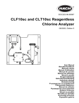
DIAGNOSTIKA: Analüsaator jälgib pidevalt iseennast ja
andurit/andureid probleemsete tingimuste osas. Taoliste
tingimusteilmnemiselvilgubekraanilVigaja/võiHoiatus.
EKRAAN: Mõõtmistulemused kuvatakse reaalajas suurte
numbritega kõrge kontrastiga LCD-ekraanile, lisaks on
võimalik kuvada kuni nelja protsessimuutujat või diagnostilist
parameetrit. Ekraan on taustvalgusega ning selle formaati
on võimalik muuta vastavalt kasutaja vajadustele.
LOKALISEERITUD KEELED: Rosemount Analyticali üle
maailma müüdavad tooted on lokaliseeritud seitsmesse
keelde - inglise, prantsuse, saksa, itaalia, hispaania, portugali
ja hiina. Kõigil seadmetel on kasutaja programmeeritavad
menüüd, kalibreerimisprotseduurid, veateated ja hoiatused
ning kasutaja abimenüüd olemas kõigis seitsmes keeles.
Kuvatavat keelt on võimalik hõlpsast muuta vastava menüü
abil.
VOOLUVÄLJUNDID: Kaks 4-20 mA või 0-20 mA isoleeritud
voolu väljundit. Väljundid on skaleeritavad ning neid on
võimalik programmeerida lineaarselt või logaritmiliselt.
Väljundi summutamise saab sisse lülitada ajapiiranguga 0
kuni 999 sekundit. Väljund 1 sisaldab ka digitaalset 4-20mA-
listHARTsignaali(ainultvariandis-HT)
ERIMÕÕTMISED: Mudelit 1056 saab kasutada paljude
erinevate kasutuste mõõtmiseks.
•Hägususe mõõtmine ühe või kahe anduriga: Ideaalne
olmerakendustes madala NTU väärtusega ltreeritud
joogivee hägususe mõõtmiseks. Kasutada koos Clarity II
anduri, andurite kaabli ja gaasiärastajaga.
•Juhtivuse mõõtmine 4 elektroodiga: 1056 ühildub
Rosemount Analytical 4-elektroodilise mudeliga
MODEL 1056 SECTION 1.0
DESCRIPTION AND SPECIFICATIONS
2
DIAGNOSTICS: The analyzer continuously monitors
itself and the sensor(s) for problematic conditions.
The display flashes Fault and/or Warning when these
conditions occur.
DISPLAY: The high-contrast LCD provides live
measurement readouts in large digits and shows up to
four additional process variables or diagnostic
parameters. The display is back-lit and the format can
be customized to meet user requirements.
LOCAL LANGUAGES :
Rosemount Analytical extends its worldwide reach by
offering seven local languages – English, French,
German, Italian, Spanish, Portuguese, and Chinese.
Every unit includes user programming menus; calibration
routines; faults and warnings; and user help screens
in all seven languages. The displayed language can
be easily set and changed using the menus.
CURRENT OUTPUTS: Two 4-20 mA or 0-20 mA current
outputs are electrically isolated. Outputs are fully scalable
and can be programmed to linear or logarithmic
modes. Output dampening can be enabled with time
constants from 0 to 999 seconds. Output 1 includes
digital signal 4-20 mA superimposed HART (option -HT
only)
SPECIAL MEASUREMENTS: The Model 1056 offers
measuring capabilities for many applications.
l
Single or Dual Turbidity: Ideal in municipal appli-
cations for measurement of low-NTU filtered drinking
water. Must be used with Clarity II sensor, sensor cable
and debubbler.
l 4-Electrode Conductivity:
The 1056 is compatible with Rosemount
Analytical 4-electrode Model 410VP in the PUR-SENSE
family of conductivity sensors. This sensor supports
a wide array of applications and is capable of measuring
a large range of conductivity with one geometric
configuration. Wired to the 1056, this sensor can
measure 2μS/cm to 300mS/cm with an accuracy of 4%
of reading throughout the entire range.
l 4-20mA Current Input: Accepts any analog current
input from an external device for temperature compen-
sation of measurements and atmospheric pressure
input for partial pressure correction of oxygen.
l Selective Ions: The analyzer is able to measure
ammonia and fluoride using commercially available
ion-selective electrodes. All analyzers with installed pH
boards can be programmed to measure selective ions.
l pH Independent Free Chlorine: With Rosemount
Analytical’s 498Cl-01 sensor, the analyzer is able to
measure free chlorine with automatic correction for
process pH without the need for a pH sensor.
l Inferential pH: The analyzer is able to derive and
display inferred pH (pHCalc) using two contacting con-
ductivity signal boards and the appropriate contacting
conductivity sensors. This method will calculate the
pH of condensate and boiler water from conductivity
and cation conductivity measurements.
l
Differential Conductivity: Dual input conductivity
configurations can measure differential conductivity.
The analyzer can be programmed to display dual
conductivity as ratio, % rejection, or % passage.
S1: 1.234µS/cm 25.0ºC
S2: 12.34pH 25.0ºC
Diagnostics
Faults
Warnings
Sensor 1
Sensor 2
Out 1: 12.05 mA
Out 2: 12.05 mA
1056-01-20-32-HT
Instr SW VER: 2.12
AC Freq. Used: 60Hz
Information about
each condition
is quickly accessible
by pressing DIAG on
the keypad. User
help screens are
displayed for most
fault and warning
conditions to assist in
troubleshooting.
Model T1056
Clarity
®
II
Turbidimeter
System
410VP, mis kuulub juhtivusandurite PUR-
SENSE perekonda. See andur toetab mitmesuguseid
rakendusi ning suudab üheainsa geomeetrilise
konguratsiooniga mõõta juhtivust laias vahemikus.
1056 külge ühendatult mõõdab see andur juhtivust kogu
mõõtmispiirkonnas(2μS/cmkuni300mS/cm)4-protsendilise
täpsusega.
•4-20mA voolusisend:Võtab vastu mis tahes välisseadmest
tulevat analoog-voolusisendit näitude temperatuuri
kompenseerimiseks ning atmosfäärirõhu sisendit hapniku
rõhu osaliseks kompenseerimiseks.
•Selektiivsed ioonid: Analüsaatoriga saab mõõta
ammoniaagi-jauoriidisisaldust,kasutadeskaubandusvõrgus
saadaolevaid ioonselektiivseid elektroode (ISE). Kõiki
analüsaatoreid, millele on paigaldatud pH-moodul, saab
programmeerida mõõtma selektiivseid ioone.
•pH-sõltumatu vaba kloor: Rosemount Analytical 498Cl-01
anduriga suudab analüsaator mõõta vaba kloori sisaldust
protsessi-pH automaatse korrigeerimisega, ilma et pH-
andurit vaja läheks.
•Tuletatud pH:Analüsaator kasutab tuletatud pH (pHCalc)
leidmiseks ja kuvamiseks kaht juhtivuse kontaktmõõtmise
signaalmoodulit ning vastavaid juhtivuse kontaktmõõtmise
andureid. Selle meetodiga arvutatakse kondensaadi ja
katlaveepHjuhtivusejakatioonidejuhtivusenäitudepõhjal.
•Juhtivuste diferentsiaal: Kahesisendiline juhtivusmõõtmiste
konguratsioon võimaldab mõõta juhtivuste diferentsiaali.
Analüsaatorit saab programmeerida näitama kaksikjuhtivust
kas suhtena, protsentuaalse summutusena või protsentuaalse
läbipääsuna.
MODEL 1056 SECTION 1.0
DESCRIPTION AND SPECIFICATIONS
2
DIAGNOSTICS: The analyzer continuously monitors
itself and the sensor(s) for problematic conditions.
The display flashes Fault and/or Warning when these
conditions occur.
DISPLAY: The high-contrast LCD provides live
measurement readouts in large digits and shows up to
four additional process variables or diagnostic
parameters. The display is back-lit and the format can
be customized to meet user requirements.
LOCAL LANGUAGES :
Rosemount Analytical extends its worldwide reach by
offering seven local languages – English, French,
German, Italian, Spanish, Portuguese, and Chinese.
Every unit includes user programming menus; calibration
routines; faults and warnings; and user help screens
in all seven languages. The displayed language can
be easily set and changed using the menus.
CURRENT OUTPUTS: Two 4-20 mA or 0-20 mA current
outputs are electrically isolated. Outputs are fully scalable
and can be programmed to linear or logarithmic
modes. Output dampening can be enabled with time
constants from 0 to 999 seconds. Output 1 includes
digital signal 4-20 mA superimposed HART (option -HT
only)
SPECIAL MEASUREMENTS: The Model 1056 offers
measuring capabilities for many applications.
l
Single or Dual Turbidity: Ideal in municipal appli-
cations for measurement of low-NTU filtered drinking
water. Must be used with Clarity II sensor, sensor cable
and debubbler.
l 4-Electrode Conductivity:
The 1056 is compatible with Rosemount
Analytical 4-electrode Model 410VP in the PUR-SENSE
family of conductivity sensors. This sensor supports
a wide array of applications and is capable of measuring
a large range of conductivity with one geometric
configuration. Wired to the 1056, this sensor can
measure 2μS/cm to 300mS/cm with an accuracy of 4%
of reading throughout the entire range.
l 4-20mA Current Input: Accepts any analog current
input from an external device for temperature compen-
sation of measurements and atmospheric pressure
input for partial pressure correction of oxygen.
l Selective Ions: The analyzer is able to measure
ammonia and fluoride using commercially available
ion-selective electrodes. All analyzers with installed pH
boards can be programmed to measure selective ions.
l pH Independent Free Chlorine: With Rosemount
Analytical’s 498Cl-01 sensor, the analyzer is able to
measure free chlorine with automatic correction for
process pH without the need for a pH sensor.
l Inferential pH: The analyzer is able to derive and
display inferred pH (pHCalc) using two contacting con-
ductivity signal boards and the appropriate contacting
conductivity sensors. This method will calculate the
pH of condensate and boiler water from conductivity
and cation conductivity measurements.
l
Differential Conductivity: Dual input conductivity
configurations can measure differential conductivity.
The analyzer can be programmed to display dual
conductivity as ratio, % rejection, or % passage.
S1: 1.234µS/cm 25.0ºC
S2: 12.34pH 25.0ºC
Diagnostics
Faults
Warnings
Sensor 1
Sensor 2
Out 1: 12.05 mA
Out 2: 12.05 mA
1056-01-20-32-HT
Instr SW VER: 2.12
AC Freq. Used: 60Hz
Information about
each condition
is quickly accessible
by pressing DIAG on
the keypad. User
help screens are
displayed for most
fault and warning
conditions to assist in
troubleshooting.
Model T1056
Clarity
®
II
Turbidimeter
System
Mudel T1056
Clarity®II
Turbidimeter
System
MODEL 1056 SECTION 1.0
DESCRIPTION AND SPECIFICATIONS
2
DIAGNOSTICS: The analyzer continuously monitors
itself and the sensor(s) for problematic conditions.
The display flashes Fault and/or Warning when these
conditions occur.
DISPLAY: The high-contrast LCD provides live
measurement readouts in large digits and shows up to
four additional process variables or diagnostic
parameters. The display is back-lit and the format can
be customized to meet user requirements.
LOCAL LANGUAGES :
Rosemount Analytical extends its worldwide reach by
offering seven local languages – English, French,
German, Italian, Spanish, Portuguese, and Chinese.
Every unit includes user programming menus; calibration
routines; faults and warnings; and user help screens
in all seven languages. The displayed language can
be easily set and changed using the menus.
CURRENT OUTPUTS: Two 4-20 mA or 0-20 mA current
outputs are electrically isolated. Outputs are fully scalable
and can be programmed to linear or logarithmic
modes. Output dampening can be enabled with time
constants from 0 to 999 seconds. Output 1 includes
digital signal 4-20 mA superimposed HART (option -HT
only)
SPECIAL MEASUREMENTS: The Model 1056 offers
measuring capabilities for many applications.
l
Single or Dual Turbidity: Ideal in municipal appli-
cations for measurement of low-NTU filtered drinking
water. Must be used with Clarity II sensor, sensor cable
and debubbler.
l 4-Electrode Conductivity:
The 1056 is compatible with Rosemount
Analytical 4-electrode Model 410VP in the PUR-SENSE
family of conductivity sensors. This sensor supports
a wide array of applications and is capable of measuring
a large range of conductivity with one geometric
configuration. Wired to the 1056, this sensor can
measure 2μS/cm to 300mS/cm with an accuracy of 4%
of reading throughout the entire range.
l 4-20mA Current Input: Accepts any analog current
input from an external device for temperature compen-
sation of measurements and atmospheric pressure
input for partial pressure correction of oxygen.
l Selective Ions: The analyzer is able to measure
ammonia and fluoride using commercially available
ion-selective electrodes. All analyzers with installed pH
boards can be programmed to measure selective ions.
l pH Independent Free Chlorine: With Rosemount
Analytical’s 498Cl-01 sensor, the analyzer is able to
measure free chlorine with automatic correction for
process pH without the need for a pH sensor.
l Inferential pH: The analyzer is able to derive and
display inferred pH (pHCalc) using two contacting con-
ductivity signal boards and the appropriate contacting
conductivity sensors. This method will calculate the
pH of condensate and boiler water from conductivity
and cation conductivity measurements.
l
Differential Conductivity: Dual input conductivity
configurations can measure differential conductivity.
The analyzer can be programmed to display dual
conductivity as ratio, % rejection, or % passage.
S1: 1.234µS/cm 25.0ºC
S2: 12.34pH 25.0ºC
Diagnostics
Faults
Warnings
Sensor 1
Sensor 2
Out 1: 12.05 mA
Out 2: 12.05 mA
1056-01-20-32-HT
Instr SW VER: 2.12
AC Freq. Used: 60Hz
Information about
each condition
is quickly accessible
by pressing DIAG on
the keypad. User
help screens are
displayed for most
fault and warning
conditions to assist in
troubleshooting.
Model T1056
Clarity
®
II
Turbidimeter
System
Kõigi tingimuste
kohta saab teavet, kui
vajutada klaviatuuril
nuppu DIAG.
Enamus vea- ja
hoiatustingimuste
esinemiste korral
kuvatakse abiaken,
mis aitab kasutajat
veatuvastamisel.

3
SPETSIFIKATSIOON - Üldine
Korpus: Polükarbonaadist. NEMA 4X/CSA 4 (IP65).
Mõõtmed: Välimised 155 x 155 x 131mm (6.10 x 6.10 x
5.15 tolli). Liist: 1/2 DIN 139mm x 139mm (5.45 x 5.45 tolli)
Juhtmesisendid: Sobivad 1/2" või PG13,5 juhtme
ühendused Ekraan: Monokroomne vedelkristallekraan 128
x 96 piksliga ekraanilahutus. Taustvalgus: aktiivne ekraani
ala: 58 x 78mm (2.3 x 3.0 tolli).
Keskkonna temperatuur ja niiskus: 0-55°C (32-
131°F).Hägususepuhul:0-50°C(32-122°F),RH5-95%
(mittekondenseeruv)
Ladustamistemperatuur:-20-60°C (-4-140°F).
Ohtlikud keskkonnad -
CSA valikud: -01, 02, 03, 20, 21, 22, 24, 25, 26,
27,30,31,32,34,35,36,37,38,AN,jaHT.
MODEL 1056 SECTION 1.0
DESCRIPTION AND SPECIFICATIONS
3
SPECIFICATIONS - General
Enclosure: Polycarbonate. NEMA 4X/CSA 4 (IP65).
Dimensions: Overall 155 x 155 x 131mm (6.10 x 6.10
x 5.15 in.). Cutout: 1/2 DIN 139mm x 139mm (5.45 x
5.45 in.)
Conduit Openings: Accepts 1/2” or PG13.5 conduit
fittings
Display: Monochromatic graphic liquid crystal display.
128 x 96 pixel display resolution. Backlit. Active
display area: 58 x 78mm (2.3 x 3.0 in.).
Ambient Temperature and Humidity: 0 to 55°C
(32 to 131°F). Turbidity only: 0 to 50°C (32 to
122°F), RH 5 to 95% (non-condensing)
Storage Temperature Effect: -20 to 60ºC (-4 to 140°F)
Power: Code -01: 115/230 VAC ±15%, 50/60 Hz. 10W.
Code -02: 20 to 30 VDC. 15 W.
Code -03: 85 to 265 VAC, 47.5 to 65.0 Hz, switching.
15 W.
Note: Code -02 and -03 power supplies include 4 pro-
grammable relays
Equipment protected by double insulation
Alarms relays*: Four alarm relays for process meas-
urement(s) or temperature. Any relay can be config-
ured as a fault alarm instead of a process alarm. Each
relay can be configured independently and each can
be programmed with interval timer settings.
Relays: Form C, SPDT, epoxy sealed
Inductive load: 1/8 HP motor (max.), 40 VAC
*Relays only available with -02 power supply (20 - 30 VDC) or -03
switching power supply (85 - 265 VAC)
Inputs: One or two isolated sensor inputs
Outputs: Two 4-20 mA or 0-20 mA isolated current out-
puts. Fully scalable. Max Load: 550 Ohm. Output 1
has superimposed HART signal (configurations
1056-0X-2X-3X-HT only)
Current Output Accuracy: ±0.05 mA @ 25 ºC
Terminal Connections Rating: Power connector
(3-leads): 24-12 AWG wire size. Signal board ter-
minal blocks: 26-16 AWG wire size. Current output
connectors (2-leads): 24-16 AWG wire size. Alarm
relay terminal blocks: 24-12 AWG wire size
(-02 24 VDC power supply and -03 85-265VAC
power supply)
Weight/Shipping Weight: (rounded up to nearest lb or
nearest 0.5 kg): 3 lbs/4 lbs (1.5 kg/2.0 kg)
RFI/EMI: EN-61326
LVD: EN-61010-1
Hazardous Location Approvals -
Options for CSA: -01, 02, 03, 20, 21, 22, 24, 25, 26,
27, 30, 31, 32, 34, 35, 36, 37, 38, AN, and HT.
Class I, Division 2, Groups A, B, C, & D
Class Il, Division 2, Groups E, F, & G
Class Ill T4A Tamb= 50
°C
Evaluated to the ANSI/UL Standards. The ‘C’ and ‘US’ indi-
cators adjacent to the CSA Mark signify that the product has
been evaluated to the applicable CSA and ANSI/UL
Standards, for use in Canada and the U.S. respectively
Class I, Division 2, Groups A, B, C, & D
Class Il & lll, Division 2, Groups E, F, & G
T4A Tamb= 50
°C Enclosure Type 4X
CAUTION
RISK OF ELECTRICAL SHOCK
Maximum Relay Current
Resistive
28 VDC 5.0 A
115 VAC 5.0 A
230 VAC 5.0 A
POLLUTION DEGREE 2: Normally only non-conductive
pollution occurs. Occasionally, however, a temporary
conductivity caused by condensation must be expected.
Altitude: for use up to 2000 meter (6562 ft.)
WARNING
Exposure to some chemicals may degrade the
sealing properties used in the following devices:
Zettler Relays (K1-K4) PN AZ8-1CH-12DSEA
WARNING
Options for FM: -01, 02, 03, 20, 21, 22, 24, 25, 26, 30,
31, 32, 34, 35, 36, 38, AN, and HT.
Klass I, Divisjon 2, Grupid A, B, C ja D
Klass II, Divisjon 2, Grupd E, F ja G
Klass Ill T4A Tamb= 50°C
Vastab ANSI/UL nõuetele. C ja US märked CSA märgi kõrval näitavad, et
toode vastab CSA ja ANSI/UL nõuetele Kanadas ja USA-s kasutamiseks.
FM valikud: -01, 02, 03, 20, 21, 22, 24, 25, 26, 30,
31,32,34,35,36,38,AN,jaHT.
MODEL 1056 SECTION 1.0
DESCRIPTION AND SPECIFICATIONS
3
SPECIFICATIONS - General
Enclosure: Polycarbonate. NEMA 4X/CSA 4 (IP65).
Dimensions: Overall 155 x 155 x 131mm (6.10 x 6.10
x 5.15 in.). Cutout: 1/2 DIN 139mm x 139mm (5.45 x
5.45 in.)
Conduit Openings: Accepts 1/2” or PG13.5 conduit
fittings
Display: Monochromatic graphic liquid crystal display.
128 x 96 pixel display resolution. Backlit. Active
display area: 58 x 78mm (2.3 x 3.0 in.).
Ambient Temperature and Humidity: 0 to 55°C
(32 to 131°F). Turbidity only: 0 to 50°C (32 to
122°F), RH 5 to 95% (non-condensing)
Storage Temperature Effect: -20 to 60ºC (-4 to 140°F)
Power: Code -01: 115/230 VAC ±15%, 50/60 Hz. 10W.
Code -02: 20 to 30 VDC. 15 W.
Code -03: 85 to 265 VAC, 47.5 to 65.0 Hz, switching.
15 W.
Note: Code -02 and -03 power supplies include 4 pro-
grammable relays
Equipment protected by double insulation
Alarms relays*: Four alarm relays for process meas-
urement(s) or temperature. Any relay can be config-
ured as a fault alarm instead of a process alarm. Each
relay can be configured independently and each can
be programmed with interval timer settings.
Relays: Form C, SPDT, epoxy sealed
Inductive load: 1/8 HP motor (max.), 40 VAC
*Relays only available with -02 power supply (20 - 30 VDC) or -03
switching power supply (85 - 265 VAC)
Inputs: One or two isolated sensor inputs
Outputs: Two 4-20 mA or 0-20 mA isolated current out-
puts. Fully scalable. Max Load: 550 Ohm. Output 1
has superimposed HART signal (configurations
1056-0X-2X-3X-HT only)
Current Output Accuracy: ±0.05 mA @ 25 ºC
Terminal Connections Rating: Power connector
(3-leads): 24-12 AWG wire size. Signal board ter-
minal blocks: 26-16 AWG wire size. Current output
connectors (2-leads): 24-16 AWG wire size. Alarm
relay terminal blocks: 24-12 AWG wire size
(-02 24 VDC power supply and -03 85-265VAC
power supply)
Weight/Shipping Weight: (rounded up to nearest lb or
nearest 0.5 kg): 3 lbs/4 lbs (1.5 kg/2.0 kg)
RFI/EMI: EN-61326
LVD: EN-61010-1
Hazardous Location Approvals -
Options for CSA: -01, 02, 03, 20, 21, 22, 24, 25, 26,
27, 30, 31, 32, 34, 35, 36, 37, 38, AN, and HT.
Class I, Division 2, Groups A, B, C, & D
Class Il, Division 2, Groups E, F, & G
Class Ill T4A Tamb= 50
°C
Evaluated to the ANSI/UL Standards. The ‘C’ and ‘US’ indi-
cators adjacent to the CSA Mark signify that the product has
been evaluated to the applicable CSA and ANSI/UL
Standards, for use in Canada and the U.S. respectively
Class I, Division 2, Groups A, B, C, & D
Class Il & lll, Division 2, Groups E, F, & G
T4A Tamb= 50
°C Enclosure Type 4X
CAUTION
RISK OF ELECTRICAL SHOCK
Maximum Relay Current
Resistive
28 VDC 5.0 A
115 VAC 5.0 A
230 VAC 5.0 A
POLLUTION DEGREE 2: Normally only non-conductive
pollution occurs. Occasionally, however, a temporary
conductivity caused by condensation must be expected.
Altitude: for use up to 2000 meter (6562 ft.)
WARNING
Exposure to some chemicals may degrade the
sealing properties used in the following devices:
Zettler Relays (K1-K4) PN AZ8-1CH-12DSEA
WARNING
Options for FM: -01, 02, 03, 20, 21, 22, 24, 25, 26, 30,
31, 32, 34, 35, 36, 38, AN, and HT.
Klass I, Divisjon 2, Grupid A, B, C ja D
Klass II ja III, Divisjon 2, Grupd E, F ja G
T4A Tamb= 50°C Ümbrise tüüp 4X
REOSTUSASTE 2: Tavaliselt ilmneb mitte-juhtiv saastus. Kuid
aeg-ajalt võib oodata ajutist juhtivust, mille on põhjustanud
kondensatsioon. Kõrgus: kasutuseks kuni 2000 meetri kõrgusel
(6562 jalga)
Elekter:Kood-01:115/230VAC±15%,50/60Hz.10W.
Kood-02:20-30VDC.15W.
Kood-0385-265VAC,47,5-65,0Hz,ümberlülituv.15W.
Märkus: Kood -02 ja -03 toiteplokkidega on kaasas neli
programmeeritavat releed
MODEL 1056 SECTION 1.0
DESCRIPTION AND SPECIFICATIONS
3
SPECIFICATIONS - General
Enclosure: Polycarbonate. NEMA 4X/CSA 4 (IP65).
Dimensions: Overall 155 x 155 x 131mm (6.10 x 6.10
x 5.15 in.). Cutout: 1/2 DIN 139mm x 139mm (5.45 x
5.45 in.)
Conduit Openings: Accepts 1/2” or PG13.5 conduit
fittings
Display: Monochromatic graphic liquid crystal display.
128 x 96 pixel display resolution. Backlit. Active
display area: 58 x 78mm (2.3 x 3.0 in.).
Ambient Temperature and Humidity: 0 to 55°C
(32 to 131°F). Turbidity only: 0 to 50°C (32 to
122°F), RH 5 to 95% (non-condensing)
Storage Temperature Effect: -20 to 60ºC (-4 to 140°F)
Power: Code -01: 115/230 VAC ±15%, 50/60 Hz. 10W.
Code -02: 20 to 30 VDC. 15 W.
Code -03: 85 to 265 VAC, 47.5 to 65.0 Hz, switching.
15 W.
Note: Code -02 and -03 power supplies include 4 pro-
grammable relays
Equipment protected by double insulation
Alarms relays*: Four alarm relays for process meas-
urement(s) or temperature. Any relay can be config-
ured as a fault alarm instead of a process alarm. Each
relay can be configured independently and each can
be programmed with interval timer settings.
Relays: Form C, SPDT, epoxy sealed
Inductive load: 1/8 HP motor (max.), 40 VAC
*Relays only available with -02 power supply (20 - 30 VDC) or -03
switching power supply (85 - 265 VAC)
Inputs: One or two isolated sensor inputs
Outputs: Two 4-20 mA or 0-20 mA isolated current out-
puts. Fully scalable. Max Load: 550 Ohm. Output 1
has superimposed HART signal (configurations
1056-0X-2X-3X-HT only)
Current Output Accuracy: ±0.05 mA @ 25 ºC
Terminal Connections Rating: Power connector
(3-leads): 24-12 AWG wire size. Signal board ter-
minal blocks: 26-16 AWG wire size. Current output
connectors (2-leads): 24-16 AWG wire size. Alarm
relay terminal blocks: 24-12 AWG wire size
(-02 24 VDC power supply and -03 85-265VAC
power supply)
Weight/Shipping Weight: (rounded up to nearest lb or
nearest 0.5 kg): 3 lbs/4 lbs (1.5 kg/2.0 kg)
RFI/EMI: EN-61326
LVD: EN-61010-1
Hazardous Location Approvals -
Options for CSA: -01, 02, 03, 20, 21, 22, 24, 25, 26,
27, 30, 31, 32, 34, 35, 36, 37, 38, AN, and HT.
Class I, Division 2, Groups A, B, C, & D
Class Il, Division 2, Groups E, F, & G
Class Ill T4A Tamb= 50
°C
Evaluated to the ANSI/UL Standards. The ‘C’ and ‘US’ indi-
cators adjacent to the CSA Mark signify that the product has
been evaluated to the applicable CSA and ANSI/UL
Standards, for use in Canada and the U.S. respectively
Class I, Division 2, Groups A, B, C, & D
Class Il & lll, Division 2, Groups E, F, & G
T4A Tamb= 50
°C Enclosure Type 4X
CAUTION
RISK OF ELECTRICAL SHOCK
Maximum Relay Current
Resistive
28 VDC 5.0 A
115 VAC 5.0 A
230 VAC 5.0 A
POLLUTION DEGREE 2: Normally only non-conductive
pollution occurs. Occasionally, however, a temporary
conductivity caused by condensation must be expected.
Altitude: for use up to 2000 meter (6562 ft.)
WARNING
Exposure to some chemicals may degrade the
sealing properties used in the following devices:
Zettler Relays (K1-K4) PN AZ8-1CH-12DSEA
WARNING
Options for FM: -01, 02, 03, 20, 21, 22, 24, 25, 26, 30,
31, 32, 34, 35, 36, 38, AN, and HT.
Seade on kaitstud kahekordse isolatsiooniga
Alarmreleed*: Neli häirereleed protsessinäitude või
temperatuuri jaoks. Kõiki releesid saab seadistada, kas
veaalarmi või protsessialarmina. Kõiki releid saab eraldi
seadistada ning programmeerida vastavate ajaintervallide
seadistusega.
Releed: Form C, SPDT, epoksüliimiga suletud
Maks. relee voolutugevus
Takistus
28 VDC 5,0 A
115 VAC 5,0 A
230 VAC 5,0 A
Induktiivkoormus:1/8HPmootor(maks.),40VAC
ETTEVAATUST
ESSENTIAL INSTRUCTIONS
READ THIS PAGE BEFORE PROCEEDING!
Your instrument purchase from Rosemount
Analytical, Inc. is one of the finest available for your
particular application. These instruments have been
designed, and tested to meet many national and
international standards. Experience indicates that its
performance is directly related to the quality of the
installation and knowledge of the user in operating
and maintaining the instrument. To ensure their con-
tinued operation to the design specifications, per-
sonnel should read this manual thoroughly before
proceeding with installation, commissioning, opera-
tion, and maintenance of this instrument. If this
equipment is used in a manner not specified by the
manufacturer, the protection provided by it against
hazards may be impaired.
• Failure to follow the proper instructions may
cause any one of the following situations to
occur: Loss of life; personal injury; property dam-
age; damage to this instrument; and warranty
invalidation.
• Ensure that you have received the correct model
and options from your purchase order. Verify that
this manual covers your model and options. If
not, call 1-800-854-8257 or 949-757-8500 to
request correct manual.
• For clarification of instructions, contact your
Rosemount representative.
• Follow all warnings, cautions, and instructions
marked on and supplied with the product.
• Use only qualified personnel to install, operate,
update, program and maintain the product.
• Educate your personnel in the proper installation,
operation, and maintenance of the product.
• Install equipment as specified in the Installation
section of this manual. Follow appropriate local
and national codes. Only connect the product to
electrical and pressure sources specified in this
manual.
• Use only factory documented components for
repair. Tampering or unauthorized substitution of
parts and procedures can affect the performance
and cause unsafe operation of your process.
• All equipment doors must be closed and protec-
tive covers must be in place unless qualified per-
sonnel are performing maintenance.
Equipment protected throughout by double insulation.
• Installation and servicing of this product may expose personel
to dangerous voltages.
• Main power wired to separate power source must be
disconnected before servicing.
• Do not operate or energize instrument with case open!
• Signal wiring connected in this box must be rated at least
240 V.
• Non-metallic cable strain reliefs do not provide grounding
between conduit connections! Use grounding type bushings
and jumper wires.
• Unused cable conduit entries must be securely sealed by
non-flammable closures to provide enclosure integrity in
compliance with personal safety and environmental protection
requirements. Unused conduit openings must be sealed with
NEMA 4X or IP65 conduit plugs to maintain the ingress
protection rating (NEMA 4X).
• Electrical installation must be in accordance with the National
Electrical Code (ANSI/NFPA-70) and/or any other applicable
national or local codes.
• Operate only with front panel fastened and in place.
• Safety and performance require that this instrument be
connected and properly grounded through a three-wire
power source.
• Proper use and configuration is the responsibility of the
user.
This product generates, uses, and can radiate radio frequency
energy and thus can cause radio communication interference.
Improper installation, or operation, may increase such interfer-
ence. As temporarily permitted by regulation, this unit has not
been tested for compliance within the limits of Class A comput-
ing devices, pursuant to Subpart J of Part 15, of FCC Rules,
which are designed to provide reasonable protection against
such interference. Operation of this equipment in a residential
area may cause interference, in which case the user at his own
expense, will be required to take whatever measures may be
required to correct the interference.
This product is not intended for use in the light industrial,
residential or commercial environments per the instru-
ment’s certification to EN50081-2.
Emerson Process Management
2400 Barranca Parkway
Irvine, CA 92606 USA
Tel: (949) 757-8500
Fax: (949) 474-7250
http://www.rosemountanalytical.com
© Rosemount Analytical Inc. 2012
WARNING
RISK OF ELECTRICAL SHOCK
CAUTION
CAUTION
ELEKTRILÖÖGI OHT
*Releed on saadavad ainult -02 toiteploki (20 - 30 VDC) või -03 ümberlülituva
toiteplokiga (85 - 265 VAC)
HOIATUS
MODEL 1056 SECTION 1.0
DESCRIPTION AND SPECIFICATIONS
3
SPECIFICATIONS - General
Enclosure: Polycarbonate. NEMA 4X/CSA 4 (IP65).
Dimensions: Overall 155 x 155 x 131mm (6.10 x 6.10
x 5.15 in.). Cutout: 1/2 DIN 139mm x 139mm (5.45 x
5.45 in.)
Conduit Openings: Accepts 1/2” or PG13.5 conduit
fittings
Display: Monochromatic graphic liquid crystal display.
128 x 96 pixel display resolution. Backlit. Active
display area: 58 x 78mm (2.3 x 3.0 in.).
Ambient Temperature and Humidity: 0 to 55°C
(32 to 131°F). Turbidity only: 0 to 50°C (32 to
122°F), RH 5 to 95% (non-condensing)
Storage Temperature Effect: -20 to 60ºC (-4 to 140°F)
Power: Code -01: 115/230 VAC ±15%, 50/60 Hz. 10W.
Code -02: 20 to 30 VDC. 15 W.
Code -03: 85 to 265 VAC, 47.5 to 65.0 Hz, switching.
15 W.
Note: Code -02 and -03 power supplies include 4 pro-
grammable relays
Equipment protected by double insulation
Alarms relays*: Four alarm relays for process meas-
urement(s) or temperature. Any relay can be config-
ured as a fault alarm instead of a process alarm. Each
relay can be configured independently and each can
be programmed with interval timer settings.
Relays: Form C, SPDT, epoxy sealed
Inductive load: 1/8 HP motor (max.), 40 VAC
*Relays only available with -02 power supply (20 - 30 VDC) or -03
switching power supply (85 - 265 VAC)
Inputs: One or two isolated sensor inputs
Outputs: Two 4-20 mA or 0-20 mA isolated current out-
puts. Fully scalable. Max Load: 550 Ohm. Output 1
has superimposed HART signal (configurations
1056-0X-2X-3X-HT only)
Current Output Accuracy: ±0.05 mA @ 25 ºC
Terminal Connections Rating: Power connector
(3-leads): 24-12 AWG wire size. Signal board ter-
minal blocks: 26-16 AWG wire size. Current output
connectors (2-leads): 24-16 AWG wire size. Alarm
relay terminal blocks: 24-12 AWG wire size
(-02 24 VDC power supply and -03 85-265VAC
power supply)
Weight/Shipping Weight: (rounded up to nearest lb or
nearest 0.5 kg): 3 lbs/4 lbs (1.5 kg/2.0 kg)
RFI/EMI: EN-61326
LVD: EN-61010-1
Hazardous Location Approvals -
Options for CSA: -01, 02, 03, 20, 21, 22, 24, 25, 26,
27, 30, 31, 32, 34, 35, 36, 37, 38, AN, and HT.
Class I, Division 2, Groups A, B, C, & D
Class Il, Division 2, Groups E, F, & G
Class Ill T4A Tamb= 50
°C
Evaluated to the ANSI/UL Standards. The ‘C’ and ‘US’ indi-
cators adjacent to the CSA Mark signify that the product has
been evaluated to the applicable CSA and ANSI/UL
Standards, for use in Canada and the U.S. respectively
Class I, Division 2, Groups A, B, C, & D
Class Il & lll, Division 2, Groups E, F, & G
T4A Tamb= 50
°C Enclosure Type 4X
CAUTION
RISK OF ELECTRICAL SHOCK
Maximum Relay Current
Resistive
28 VDC 5.0 A
115 VAC 5.0 A
230 VAC 5.0 A
POLLUTION DEGREE 2: Normally only non-conductive
pollution occurs. Occasionally, however, a temporary
conductivity caused by condensation must be expected.
Altitude: for use up to 2000 meter (6562 ft.)
WARNING
Exposure to some chemicals may degrade the
sealing properties used in the following devices:
Zettler Relays (K1-K4) PN AZ8-1CH-12DSEA
WARNING
Options for FM: -01, 02, 03, 20, 21, 22, 24, 25, 26, 30,
31, 32, 34, 35, 36, 38, AN, and HT.
Mõningate kemikaalide mõju võib halvendada veekindlaid
omadusi järgmistel seadmete puhul:
Zettlerreleed(K1-K4)PNAZ8-1CH-12DSEA
Sisendid: Üks või kaks isoleeritud anduri sisendit
Väljundid: Kaks 4--20 mA või 0--20 mA isoleeritud voolu
väljundit. Täiesti skaleeritavad. Maks. koormus: 550 Ohm.
Väljund 1-l on lisaks HART signaal (ainult seadistused
1056-0X-2X-3X-HT)
Väljundvoolu täpsus: ±0.05 mA @ 25 ºC
Ühendusklemmide reiting: Toitekaabel (3-juhtmeline):
24-12 AWG juhtme suurus. Signaalmooduli klemmirivi:
26-16 AWG juhtme suurus. Vooluväljundi ühendused
(2-juhtmeline): 24-16 AWG juhtme suurus. Alarmrelee
klemmirivi: 24-12 AWG juhtme suurus (-02 24 VDC
vooluallikas -03 85-265VAC vooluallikas)
Kaal/kaal pakituna: (ümardatud lähima naela või
0,5 kilogrammini): 3 lbs/4 lbs (1.5 kg/2.0 kg)
MUDEL 1056 PEATÜKK 1,0
KIRJELDUS JA SPETSIFIKATSIOONID
MODEL 1056 SECTION 1.0
DESCRIPTION AND SPECIFICATIONS
3
SPECIFICATIONS - General
Enclosure: Polycarbonate. NEMA 4X/CSA 4 (IP65).
Dimensions: Overall 155 x 155 x 131mm (6.10 x 6.10
x 5.15 in.). Cutout: 1/2 DIN 139mm x 139mm (5.45 x
5.45 in.)
Conduit Openings: Accepts 1/2” or PG13.5 conduit
fittings
Display: Monochromatic graphic liquid crystal display.
128 x 96 pixel display resolution. Backlit. Active
display area: 58 x 78mm (2.3 x 3.0 in.).
Ambient Temperature and Humidity: 0 to 55°C
(32 to 131°F). Turbidity only: 0 to 50°C (32 to
122°F), RH 5 to 95% (non-condensing)
Storage Temperature Effect: -20 to 60ºC (-4 to 140°F)
Power: Code -01: 115/230 VAC ±15%, 50/60 Hz. 10W.
Code -02: 20 to 30 VDC. 15 W.
Code -03: 85 to 265 VAC, 47.5 to 65.0 Hz, switching.
15 W.
Note: Code -02 and -03 power supplies include 4 pro-
grammable relays
Equipment protected by double insulation
Alarms relays*: Four alarm relays for process meas-
urement(s) or temperature. Any relay can be config-
ured as a fault alarm instead of a process alarm. Each
relay can be configured independently and each can
be programmed with interval timer settings.
Relays: Form C, SPDT, epoxy sealed
Inductive load: 1/8 HP motor (max.), 40 VAC
*Relays only available with -02 power supply (20 - 30 VDC) or -03
switching power supply (85 - 265 VAC)
Inputs: One or two isolated sensor inputs
Outputs: Two 4-20 mA or 0-20 mA isolated current out-
puts. Fully scalable. Max Load: 550 Ohm. Output 1
has superimposed HART signal (configurations
1056-0X-2X-3X-HT only)
Current Output Accuracy: ±0.05 mA @ 25 ºC
Terminal Connections Rating: Power connector
(3-leads): 24-12 AWG wire size. Signal board ter-
minal blocks: 26-16 AWG wire size. Current output
connectors (2-leads): 24-16 AWG wire size. Alarm
relay terminal blocks: 24-12 AWG wire size
(-02 24 VDC power supply and -03 85-265VAC
power supply)
Weight/Shipping Weight: (rounded up to nearest lb or
nearest 0.5 kg): 3 lbs/4 lbs (1.5 kg/2.0 kg)
RFI/EMI: EN-61326
LVD: EN-61010-1
Hazardous Location Approvals -
Options for CSA: -01, 02, 03, 20, 21, 22, 24, 25, 26,
27, 30, 31, 32, 34, 35, 36, 37, 38, AN, and HT.
Class I, Division 2, Groups A, B, C, & D
Class Il, Division 2, Groups E, F, & G
Class Ill T4A Tamb= 50
°C
Evaluated to the ANSI/UL Standards. The ‘C’ and ‘US’ indi-
cators adjacent to the CSA Mark signify that the product has
been evaluated to the applicable CSA and ANSI/UL
Standards, for use in Canada and the U.S. respectively
Class I, Division 2, Groups A, B, C, & D
Class Il & lll, Division 2, Groups E, F, & G
T4A Tamb= 50
°C Enclosure Type 4X
CAUTION
RISK OF ELECTRICAL SHOCK
Maximum Relay Current
Resistive
28 VDC 5.0 A
115 VAC 5.0 A
230 VAC 5.0 A
POLLUTION DEGREE 2: Normally only non-conductive
pollution occurs. Occasionally, however, a temporary
conductivity caused by condensation must be expected.
Altitude: for use up to 2000 meter (6562 ft.)
WARNING
Exposure to some chemicals may degrade the
sealing properties used in the following devices:
Zettler Relays (K1-K4) PN AZ8-1CH-12DSEA
WARNING
Options for FM: -01, 02, 03, 20, 21, 22, 24, 25, 26, 30,
31, 32, 34, 35, 36, 38, AN, and HT.

4
JUHTIVUSE KONTAKTMÕÕTMINE (Koodid -20 ja -30)
SOORITUSSPETSIFIKATSIOON
Soovitatav vahemik - juhtivuse kontakmõõtmine
MUDEL 1056 PEATÜKK 1,0
KIRJELDUS JA SPETSIFIKATSIOONID
Mõõdab juhtivust vahemikus 0-600,000 μS/cm (600mS/
cm). Mõõta saab juhtivust, takistust, lahustunud tahkiste
hulka, soolsust ja kontsentratsiooni. Võimalik on mõõta viie
tavapäraselahusekontsentratsiooni(0-12%NaOH,0-15%
HCl,0-20%NaCl,ja0-25%või96-99,7%H2SO4).
Nende lahuste kontsentratsioonide juhtivuse algoritmid on
täielikult temperatuuriga kompenseeritavad. Temperatuuri
kompenseerimisevalikuidonkolm:sisestatavkalle(X%/°C),
kõrge puhtusastmega vesi (lahjendatud naatriumkloriid), ja
katioonide juhtivus (lahjendatud soolhape). Temperatuuri
kompenseerimist on võimalik välja lülitada, lubades
nii analüsaatoril näidata puhast juhtivust. Täpsema
informatsiooni saamiseks juhtivuse kontaktandurite
kasutamise ja töötamise kohta, vaadake toote infolehte.
Märkus: Kahe juhtivuse kontaktanduri kasutamisel suudab
Mudel1056tuletadaarvutatudpHväärtuse,midakutsutakse
pHCalc.pHCalconarvutatud,mittemõõdetudpH.(vajalik
Mudel 1056-0X-20-30-AN)
Märkus: Mudeliga 1056 ühilduvad mõningad 4 elektroodiga,
kõrge vahemikuga juhtivuse kontaktandurid.
Sisendi samm: määratav ajakonstant 1—999 sekundit,
vaikimisi 2 sekundit.
Reageerimisaeg:3sekundit-lõppnäidu100%
Soolsus: kasutab praktilist soolsuse skaalat
Lahustunud tahkiste kogus: Arvutatakse korrutades
juhtivust 25ºC juures 0,65-ga.
Temperatuurispetsikatsioon:
Temperatuuride vahemik 0-150ºC
Temperatuuri täpsus
Pt-1000, 0-50 ºC
± 0.1ºC
Temperatuuri täpsus
Pt-1000, Temp. > 50 ºC
± 0.5ºC
SOOVITATAVAD JUHTIVUSANDURID:
Kõik Rosemount Analytical ENDURANCE Model 400
seeria juhtivusandurid (Pt 1000 RTD) ja
MODEL 1056 SECTION 1.0
DESCRIPTION AND SPECIFICATIONS
2
DIAGNOSTICS: The analyzer continuously monitors
itself and the sensor(s) for problematic conditions.
The display flashes Fault and/or Warning when these
conditions occur.
DISPLAY: The high-contrast LCD provides live
measurement readouts in large digits and shows up to
four additional process variables or diagnostic
parameters. The display is back-lit and the format can
be customized to meet user requirements.
LOCAL LANGUAGES :
Rosemount Analytical extends its worldwide reach by
offering seven local languages – English, French,
German, Italian, Spanish, Portuguese, and Chinese.
Every unit includes user programming menus; calibration
routines; faults and warnings; and user help screens
in all seven languages. The displayed language can
be easily set and changed using the menus.
CURRENT OUTPUTS: Two 4-20 mA or 0-20 mA current
outputs are electrically isolated. Outputs are fully scalable
and can be programmed to linear or logarithmic
modes. Output dampening can be enabled with time
constants from 0 to 999 seconds. Output 1 includes
digital signal 4-20 mA superimposed HART (option -HT
only)
SPECIAL MEASUREMENTS: The Model 1056 offers
measuring capabilities for many applications.
l
Single or Dual Turbidity: Ideal in municipal appli-
cations for measurement of low-NTU filtered drinking
water. Must be used with Clarity II sensor, sensor cable
and debubbler.
l 4-Electrode Conductivity:
The 1056 is compatible with Rosemount
Analytical 4-electrode Model 410VP in the PUR-SENSE
family of conductivity sensors. This sensor supports
a wide array of applications and is capable of measuring
a large range of conductivity with one geometric
configuration. Wired to the 1056, this sensor can
measure 2μS/cm to 300mS/cm with an accuracy of 4%
of reading throughout the entire range.
l 4-20mA Current Input: Accepts any analog current
input from an external device for temperature compen-
sation of measurements and atmospheric pressure
input for partial pressure correction of oxygen.
l Selective Ions: The analyzer is able to measure
ammonia and fluoride using commercially available
ion-selective electrodes. All analyzers with installed pH
boards can be programmed to measure selective ions.
l pH Independent Free Chlorine: With Rosemount
Analytical’s 498Cl-01 sensor, the analyzer is able to
measure free chlorine with automatic correction for
process pH without the need for a pH sensor.
l Inferential pH: The analyzer is able to derive and
display inferred pH (pHCalc) using two contacting con-
ductivity signal boards and the appropriate contacting
conductivity sensors. This method will calculate the
pH of condensate and boiler water from conductivity
and cation conductivity measurements.
l
Differential Conductivity: Dual input conductivity
configurations can measure differential conductivity.
The analyzer can be programmed to display dual
conductivity as ratio, % rejection, or % passage.
S1: 1.234µS/cm 25.0ºC
S2: 12.34pH 25.0ºC
Diagnostics
Faults
Warnings
Sensor 1
Sensor 2
Out 1: 12.05 mA
Out 2: 12.05 mA
1056-01-20-32-HT
Instr SW VER: 2.12
AC Freq. Used: 60Hz
Information about
each condition
is quickly accessible
by pressing DIAG on
the keypad. User
help screens are
displayed for most
fault and warning
conditions to assist in
troubleshooting.
Model T1056
Clarity
®
II
Turbidimeter
System
Model 410 andur.
ENDURANCE
TM
seeria
juhtivusandurid
MODEL 1056 SECTION 1.0
DESCRIPTION AND SPECIFICATIONS
±0.6% of reading in recommended range
+2 to -10% of reading outside high recommended range
±5% of reading outside low recommended range
±4% of reading in recommended range
Measures conductivity in the range 0 to 600,000 μS/cm
(600mS/cm). Measurement choices are conductivity,
resistivity, total dissolved solids, salinity, and % concen-
tration. The % concentration selection includes the
choice of five common solutions (0-12% NaOH, 0-15%
HCl, 0-20% NaCl, and 0-25% or 96-99.7% H
2
SO
4
).
The conductivity concentration algorithms for these
solutions are fully temperature compensated. Three
temperature compensation options are available:
manual slope (X%/°C), high purity water (dilute sodium
chloride), and cation conductivity (dilute hydrochloric
acid). Temperature compensation can be disabled,
allowing the analyzer to display raw conductivity. For
more information concerning the use and operation of
the contacting conductivity sensors, refer to the product
data sheets.
Note: When two contacting conductivity sensors are
used, Model 1056 can derive an inferred pH value
called pHCalc. pHCalc is calculated pH, not directly
measured pH. (Model 1056-0X-20-30-AN required)
Note: Selected 4-electrode, high-range contacting
conductivity sensors are compatible with Model 1056.
Input filter: time constant 1 - 999 sec, default 2 sec.
Response time: 3 seconds to 100% of final reading
Salinity: uses Practical Salinity Scale
Total Dissolved Solids: Calculated by multiplying
conductivity at 25ºC by 0.65
RECOMMENDED SENSORS FOR CONDUCTIVITY:
All Rosemount Analytical ENDURANCE Model 400
series conductivity sensors (Pt 1000 RTD) and
Model 410 sensor.
CONTACTING CONDUCTIVITY (Codes -20 and -30)
Temperature range 0-150ºC
Temperature Accuracy,
Pt-1000, 0-50 ºC
± 0.1ºC
Temperature Accuracy,
Pt-1000, Temp. > 50 ºC
± 0.5ºC
PERFORMANCE SPECIFICATIONS
Recommended Range – Contacting Conductivity
Temperature Specifications:
ENDURANCE
TM
series of
conductivity sensors
family
4-electrode sensors
Cell Constant Linearity
Cell 0.01μS/cm 0.1μS/cm 1.0μS/cm 10μS/cm 100μS/cm 1000μS/cm 10mS/cm 100mS/cm 1000mS/cm
Constant
0.01
0.1
1.0
4-electrode
0.01μS/cm to 200μS/cm
0.1μS/cm to 2000μS/cm
1 μS/cm to 20mS/cm
2 μS/cm to 300mS/cm
200μS/cm to 6000μS/cm
2000μS/cm to 60mS/cm
20mS/cm to 600mS/cm
4
MODEL 1056 SECTION 1.0
DESCRIPTION AND SPECIFICATIONS
2
DIAGNOSTICS: The analyzer continuously monitors
itself and the sensor(s) for problematic conditions.
The display flashes Fault and/or Warning when these
conditions occur.
DISPLAY: The high-contrast LCD provides live
measurement readouts in large digits and shows up to
four additional process variables or diagnostic
parameters. The display is back-lit and the format can
be customized to meet user requirements.
LOCAL LANGUAGES :
Rosemount Analytical extends its worldwide reach by
offering seven local languages – English, French,
German, Italian, Spanish, Portuguese, and Chinese.
Every unit includes user programming menus; calibration
routines; faults and warnings; and user help screens
in all seven languages. The displayed language can
be easily set and changed using the menus.
CURRENT OUTPUTS: Two 4-20 mA or 0-20 mA current
outputs are electrically isolated. Outputs are fully scalable
and can be programmed to linear or logarithmic
modes. Output dampening can be enabled with time
constants from 0 to 999 seconds. Output 1 includes
digital signal 4-20 mA superimposed HART (option -HT
only)
SPECIAL MEASUREMENTS: The Model 1056 offers
measuring capabilities for many applications.
l Single or Dual Turbidity: Ideal in municipal appli-
cations for measurement of low-NTU filtered drinking
water. Must be used with Clarity II sensor, sensor cable
and debubbler.
l 4-Electrode Conductivity:
The 1056 is compatible with Rosemount
Analytical 4-electrode Model 410VP in the PUR-SENSE
family of conductivity sensors. This sensor supports
a wide array of applications and is capable of measuring
a large range of conductivity with one geometric
configuration. Wired to the 1056, this sensor can
measure 2μS/cm to 300mS/cm with an accuracy of 4%
of reading throughout the entire range.
l 4-20mA Current Input: Accepts any analog current
input from an external device for temperature compen-
sation of measurements and atmospheric pressure
input for partial pressure correction of oxygen.
l Selective Ions: The analyzer is able to measure
ammonia and fluoride using commercially available
ion-selective electrodes. All analyzers with installed pH
boards can be programmed to measure selective ions.
l pH Independent Free Chlorine: With Rosemount
Analytical’s 498Cl-01 sensor, the analyzer is able to
measure free chlorine with automatic correction for
process pH without the need for a pH sensor.
l Inferential pH: The analyzer is able to derive and
display inferred pH (pHCalc) using two contacting con-
ductivity signal boards and the appropriate contacting
conductivity sensors. This method will calculate the
pH of condensate and boiler water from conductivity
and cation conductivity measurements.
l
Differential Conductivity: Dual input conductivity
configurations can measure differential conductivity.
The analyzer can be programmed to display dual
conductivity as ratio, % rejection, or % passage.
S1: 1.234µS/cm 25.0ºC
S2: 12.34pH 25.0ºC
Diagnostics
Faults
Warnings
Sensor 1
Sensor 2
Out 1: 12.05 mA
Out 2: 12.05 mA
1056-01-20-32-HT
Instr SW VER: 2.12
AC Freq. Used: 60Hz
Information about
each condition
is quickly accessible
by pressing DIAG on
the keypad. User
help screens are
displayed for most
fault and warning
conditions to assist in
troubleshooting.
Model T1056
Clarity
®
II
Turbidimeter
System
perekonnast
4 elektroodiga andurid
MODEL 1056 SECTION 1.0
DESCRIPTION AND SPECIFICATIONS
±0.6% of reading in recommended range
+2 to -10% of reading outside high recommended range
±5% of reading outside low recommended range
±4% of reading in recommended range
Measures conductivity in the range 0 to 600,000 μS/cm
(600mS/cm). Measurement choices are conductivity,
resistivity, total dissolved solids, salinity, and % concen-
tration. The % concentration selection includes the
choice of five common solutions (0-12% NaOH, 0-15%
HCl, 0-20% NaCl, and 0-25% or 96-99.7% H
2
SO
4
).
The conductivity concentration algorithms for these
solutions are fully temperature compensated. Three
temperature compensation options are available:
manual slope (X%/°C), high purity water (dilute sodium
chloride), and cation conductivity (dilute hydrochloric
acid). Temperature compensation can be disabled,
allowing the analyzer to display raw conductivity. For
more information concerning the use and operation of
the contacting conductivity sensors, refer to the product
data sheets.
Note: When two contacting conductivity sensors are
used, Model 1056 can derive an inferred pH value
called pHCalc. pHCalc is calculated pH, not directly
measured pH. (Model 1056-0X-20-30-AN required)
Note: Selected 4-electrode, high-range contacting
conductivity sensors are compatible with Model 1056.
Input filter: time constant 1 - 999 sec, default 2 sec.
Response time: 3 seconds to 100% of final reading
Salinity: uses Practical Salinity Scale
Total Dissolved Solids: Calculated by multiplying
conductivity at 25ºC by 0.65
RECOMMENDED SENSORS FOR CONDUCTIVITY:
All Rosemount Analytical ENDURANCE Model 400
series conductivity sensors (Pt 1000 RTD) and
Model 410 sensor.
CONTACTING CONDUCTIVITY (Codes -20 and -30)
Temperature range 0-150ºC
Temperature Accuracy,
Pt-1000, 0-50 ºC
± 0.1ºC
Temperature Accuracy,
Pt-1000, Temp. > 50 ºC
± 0.5ºC
PERFORMANCE SPECIFICATIONS
Recommended Range – Contacting Conductivity
Temperature Specifications:
ENDURANCE
TM
series of
conductivity sensors
family
4-electrode sensors
Cell Constant Linearity
Cell 0.01μS/cm 0.1μS/cm 1.0μS/cm 10μS/cm 100μS/cm 1000μS/cm 10mS/cm 100mS/cm 1000mS/cm
Constant
0.01
0.1
1.0
4-electrode
0.01μS/cm to 200μS/cm
0.1μS/cm to 2000μS/cm
1 μS/cm to 20mS/cm
2 μS/cm to 300mS/cm
200μS/cm to 6000μS/cm
2000μS/cm to 60mS/cm
20mS/cm to 600mS/cm
4
MODEL 1056 SECTION 1.0
DESCRIPTION AND SPECIFICATIONS
±0.6% of reading in recommended range
+2 to -10% of reading outside high recommended range
±5% of reading outside low recommended range
±4% of reading in recommended range
Measures conductivity in the range 0 to 600,000 μS/cm
(600mS/cm). Measurement choices are conductivity,
resistivity, total dissolved solids, salinity, and % concen-
tration. The % concentration selection includes the
choice of five common solutions (0-12% NaOH, 0-15%
HCl, 0-20% NaCl, and 0-25% or 96-99.7% H
2
SO
4
).
The conductivity concentration algorithms for these
solutions are fully temperature compensated. Three
temperature compensation options are available:
manual slope (X%/°C), high purity water (dilute sodium
chloride), and cation conductivity (dilute hydrochloric
acid). Temperature compensation can be disabled,
allowing the analyzer to display raw conductivity. For
more information concerning the use and operation of
the contacting conductivity sensors, refer to the product
data sheets.
Note: When two contacting conductivity sensors are
used, Model 1056 can derive an inferred pH value
called pHCalc. pHCalc is calculated pH, not directly
measured pH. (Model 1056-0X-20-30-AN required)
Note: Selected 4-electrode, high-range contacting
conductivity sensors are compatible with Model 1056.
Input filter: time constant 1 - 999 sec, default 2 sec.
Response time: 3 seconds to 100% of final reading
Salinity: uses Practical Salinity Scale
Total Dissolved Solids: Calculated by multiplying
conductivity at 25ºC by 0.65
RECOMMENDED SENSORS FOR CONDUCTIVITY:
All Rosemount Analytical ENDURANCE Model 400
series conductivity sensors (Pt 1000 RTD) and
Model 410 sensor.
CONTACTING CONDUCTIVITY (Codes -20 and -30)
Temperature range 0-150ºC
Temperature Accuracy,
Pt-1000, 0-50 ºC
± 0.1ºC
Temperature Accuracy,
Pt-1000, Temp. > 50 ºC
± 0.5ºC
PERFORMANCE SPECIFICATIONS
Recommended Range – Contacting Conductivity
Temperature Specifications:
ENDURANCE
TM
series of
conductivity sensors
family
4-electrode sensors
Cell Constant Linearity
Cell 0.01μS/cm 0.1μS/cm 1.0μS/cm 10μS/cm 100μS/cm 1000μS/cm 10mS/cm 100mS/cm 1000mS/cm
Constant
0.01
0.1
1.0
4-electrode
0.01μS/cm to 200μS/cm
0.1μS/cm to 2000μS/cm
1 μS/cm to 20mS/cm
2 μS/cm to 300mS/cm
200μS/cm to 6000μS/cm
2000μS/cm to 60mS/cm
20mS/cm to 600mS/cm
4
4 elektroodiga
Elemendi konstandi lineaarsus
±0,6%näidustsoovitatavasvahemikus
+2-10%näidustväljaspoolsoovitatudvahemikukõrgpunkti
±5%näidustväljaspoolsoovitatavavahemikualumistpunkti
±4%näidustsoovitatavasvahemikus
Elemendi
konstant

5
MODEL 1056 SECTION 1.0
DESCRIPTION AND SPECIFICATIONS
Model 1μ
S/cm 10μS/cm 100μS/cm 1000μS/cm 10mS/cm 100mS/cm 1000mS/cm 2000mS/cm
5μS/cm to 500mS/cm
15μS/cm to 1500mS/cm
500mS/cm to 2000mS/cm
500μ
S/cm to 2000mS/cm
100μ
S/cm to 2000mS/cm
1500mS/cm to 2000mS/cm
226
242
222
(1in & 2in)
225 & 228
Measures conductivity in the range of 1 (one) μS/cm to
2,000,000 μS/cm (2 S/cm), Measurement choices are
conductivity, resistivity, total dissolved solids, salinity,
and % concentration. The % concentration selection
includes the choice of five common solutions (0-12%
NaOH, 0-15% HCl, 0-20% NaCl, and 0-25% or
96-99.7% H
2
SO
4
). The conductivity concentration
algorithms for these solutions are fully temperature
compensated. For other solutions, a simple-to-use
menu allows the customer to enter his own data. The
analyzer accepts as many as five data points and fits
either a linear (two points) or a quadratic function (three
or more points) to the data. Two temperature compensation
options are available: manual slope (X%/°C) and neutral
salt (dilute sodium chloride). Temperature compensation
can be disabled, allowing the analyzer to display raw
conductivity. Reference temperature and linear temper-
ature slope may also be adjusted for optimum results.
For more information concerning the use and operation
of the toroidal conductivity sensors, refer to the product
data sheets.
Repeatability: ±0.25% ±5 μS/cm after zero cal
Input filter: time constant 1 - 999 sec, default 2 sec.
Response time: 3 seconds to 100% of final reading
Salinity: uses Practical Salinity Scale
Total Dissolved Solids: Calculated by multiplying
conductivity at 25ºC by 0.65
Temperature Specifications:
RECOMMENDED SENSORS:
All Rosemount Analytical submersion/immersion and
flow-through toroidal sensors.
TOROIDAL CONDUCTIVITY (Codes -21 and -31)
Temperature range -25 to 210ºC (-13 to 410ºF)
Temperature Accuracy,
Pt-100, -25 to 50 ºC
± 0.5ºC
Temperature Accuracy,
Pt-100,. 50 to 210ºC
± 1ºC
PERFORMANCE SPECIFICATIONS
Recommended Range - Toroidal Conductivity
Model 226: ±1% of reading ±5μS/cm in recommended range
Models 225 & 228: ±1% of reading ±10μS/cm in recommended range
Models 222,242: ±4% of reading in recommended range
Model 225, 226 & 228: ±5% of reading outside high recommended range
Model 226: ±5μS/cm outside low recommended range
Models 225 & 228: ±15μS/cm outside low recommended range
High performance toroidal conductivity sensors
Models 226 and 225
LOOP PERFORMANCE (Following Calibration)
5
JUHTIVUS TOROIDAALNE MÕÕTMINE (Koodid -21 ja -31)
SOORITUSSPETSIFIKATSIOON
Soovitatav vahemik - juhtivus toroidaalne mõõtmine
MUDEL 1056 PEATÜKK 1,0
KIRJELDUS JA SPETSIFIKATSIOONID
Mõõdabjuhtivustvahemikus1-2000000μS/cm(2S/cm),
mõõta on võimalik juhtivust, takistust, lahustunud tahkiste
hulka, soolsust ja kontsentratsiooni. Võimalik on mõõta
viie tavapärase lahuse kontsentratsiooni (0-12% NaOH,
0-15%HCl,0-20%NaCl,ja0-25%või96-99,7%H2SO4).
Nende lahuste kontsentratsioonide juhtivuse algoritmid on
täielikult temperatuuriga kompenseeritavad. Muude lahuste
jaoks saab klient hõlpsasti kasutatava menüü abil sisestada
omad andmed. Analüsaator kasutab kuni viit andmepunkti
ja rakendab andmetele kas lineaarset (kahepunktilist) või
ruutfuntsiooni (kolm ja enam andmepunkti). Temperatuuri
kompenseerimise valikuid on kaks: sisestatav kalle
(X%/°C) ja neutraalne sool (lahjendatud naatriumkloriid).
Temperatuuri kompenseerimist on võimalik välja lülitada,
lubades nii analüsaatoril näidata puhast juhtivust.
Võrdlustemperatuuri ja lineaarse temperatuuri kallet on
võimalik parimate tulemuste saamiseks muuta. Täpsema
informatsiooni saamiseks juhtivuse toroidaalsete andurite
kasutamise ja töötamise kohta, vaadake toote infolehte.
Korratavus:±0,25%±5μS/cmpärast0-kalibr.
Sisendi samm: määratav ajakonstant 1—999 sekundit,
vaikimisi 2 sekundit.
Reageerimisaeg:3sekundit-lõppnäidu100%
Soolsus: kasutab praktilist soolsuse skaalat
Lahustunud tahkiste kogus: Arvutatakse korrutades
juhtivust 25ºC juures 0,65-ga.
Temperatuurispetsikatsioon:
Temperatuuride
vahemik
-25 - 210ºC (-13 - 410ºF)
Temperatuuri täpsus
Pt-100, -25 - 50 ºC
± 0.5ºC
Temperatuuri täpsus
Pt-100,. 50 - 210ºC
± 1ºC
SOOVITATUD ANDURID:
Kõik Rosemount Analyticali uputatavad ja läbivooluga
toroidaalsed andurid.
Suure jõudlusega toroidaalsed juhtivusandurid
Mudel 226 ja 225
MODEL 1056 SECTION 1.0
DESCRIPTION AND SPECIFICATIONS
Model 1μS/cm 10μS/cm 100μS/cm 1000μS/cm 10mS/cm 100mS/cm 1000mS/cm 2000mS/cm
5μS/cm to 500mS/cm
15μS/cm to 1500mS/cm
500mS/cm to 2000mS/cm
500μS/cm to 2000mS/cm
100μS/cm to 2000mS/cm
1500mS/cm to 2000mS/cm
226
242
222
(1in & 2in)
225 & 228
Measures conductivity in the range of 1 (one) μS/cm to
2,000,000 μS/cm (2 S/cm), Measurement choices are
conductivity, resistivity, total dissolved solids, salinity,
and % concentration. The % concentration selection
includes the choice of five common solutions (0-12%
NaOH, 0-15% HCl, 0-20% NaCl, and 0-25% or
96-99.7% H
2
SO
4
). The conductivity concentration
algorithms for these solutions are fully temperature
compensated. For other solutions, a simple-to-use
menu allows the customer to enter his own data. The
analyzer accepts as many as five data points and fits
either a linear (two points) or a quadratic function (three
or more points) to the data. Two temperature compensation
options are available: manual slope (X%/°C) and neutral
salt (dilute sodium chloride). Temperature compensation
can be disabled, allowing the analyzer to display raw
conductivity. Reference temperature and linear temper-
ature slope may also be adjusted for optimum results.
For more information concerning the use and operation
of the toroidal conductivity sensors, refer to the product
data sheets.
Repeatability: ±0.25% ±5 μS/cm after zero cal
Input filter: time constant 1 - 999 sec, default 2 sec.
Response time: 3 seconds to 100% of final reading
Salinity: uses Practical Salinity Scale
Total Dissolved Solids: Calculated by multiplying
conductivity at 25ºC by 0.65
Temperature Specifications:
RECOMMENDED SENSORS:
All Rosemount Analytical submersion/immersion and
flow-through toroidal sensors.
TOROIDAL CONDUCTIVITY (Codes -21 and -31)
Temperature range -25 to 210ºC (-13 to 410ºF)
Temperature Accuracy,
Pt-100, -25 to 50 ºC
± 0.5ºC
Temperature Accuracy,
Pt-100,. 50 to 210ºC
± 1ºC
PERFORMANCE SPECIFICATIONS
Recommended Range - Toroidal Conductivity
Model 226: ±1% of reading ±5μS/cm in recommended range
Models 225 & 228: ±1% of reading ±10μS/cm in recommended range
Models 222,242: ±4% of reading in recommended range
Model 225, 226 & 228: ±5% of reading outside high recommended range
Model 226: ±5μS/cm outside low recommended range
Models 225 & 228: ±15μS/cm outside low recommended range
High performance toroidal conductivity sensors
Models 226 and 225
LOOP PERFORMANCE (Following Calibration)
5
MODEL 1056 SECTION 1.0
DESCRIPTION AND SPECIFICATIONS
Model 1μS/cm 10μS/cm 100μS/cm 1000μS/cm 10mS/cm 100mS/cm 1000mS/cm 2000mS/cm
5μS/cm to 500mS/cm
15μS/cm to 1500mS/cm
500mS/cm to 2000mS/cm
500μ
S/cm to 2000mS/cm
100μ
S/cm to 2000mS/cm
1500mS/cm to 2000mS/cm
226
242
222
(1in & 2in)
225 & 228
Measures conductivity in the range of 1 (one) μS/cm to
2,000,000 μS/cm (2 S/cm), Measurement choices are
conductivity, resistivity, total dissolved solids, salinity,
and % concentration. The % concentration selection
includes the choice of five common solutions (0-12%
NaOH, 0-15% HCl, 0-20% NaCl, and 0-25% or
96-99.7% H
2
SO
4
). The conductivity concentration
algorithms for these solutions are fully temperature
compensated. For other solutions, a simple-to-use
menu allows the customer to enter his own data. The
analyzer accepts as many as five data points and fits
either a linear (two points) or a quadratic function (three
or more points) to the data. Two temperature compensation
options are available: manual slope (X%/°C) and neutral
salt (dilute sodium chloride). Temperature compensation
can be disabled, allowing the analyzer to display raw
conductivity. Reference temperature and linear temper-
ature slope may also be adjusted for optimum results.
For more information concerning the use and operation
of the toroidal conductivity sensors, refer to the product
data sheets.
Repeatability: ±0.25% ±5 μS/cm after zero cal
Input filter: time constant 1 - 999 sec, default 2 sec.
Response time: 3 seconds to 100% of final reading
Salinity: uses Practical Salinity Scale
Total Dissolved Solids: Calculated by multiplying
conductivity at 25ºC by 0.65
Temperature Specifications:
RECOMMENDED SENSORS:
All Rosemount Analytical submersion/immersion and
flow-through toroidal sensors.
TOROIDAL CONDUCTIVITY (Codes -21 and -31)
Temperature range -25 to 210ºC (-13 to 410ºF)
Temperature Accuracy,
Pt-100, -25 to 50 ºC
± 0.5ºC
Temperature Accuracy,
Pt-100,. 50 to 210ºC
± 1ºC
PERFORMANCE SPECIFICATIONS
Recommended Range - Toroidal Conductivity
Model 226: ±1% of reading ±5μS/cm in recommended range
Models 225 & 228: ±1% of reading ±10μS/cm in recommended range
Models 222,242: ±4% of reading in recommended range
Model 225, 226 & 228: ±5% of reading outside high recommended range
Model 226: ±5μS/cm outside low recommended range
Models 225 & 228: ±15μS/cm outside low recommended range
High performance toroidal conductivity sensors
Models 226 and 225
LOOP PERFORMANCE (Following Calibration)
5
Mudel
(1" ja 2")
TSÜKLI TULEMUSLIKKUS (pärast kalibreerimist)
Mudel226:±1%näidust±5μS/cmsoovitatavasvahemikus
Mudel225ja228:±1%näidust±10μS/cmsoovitatavasvahemikus
Mudelid222,242:±4%näidustsoovitatavasvahemikus
Mudelid225,226ja228:±5%näidustväljaspoolsoovitatavavahemikuülemistpunkti
Mudel226:±5μS/cmväljaspoolsoovitatavavahemikualumistpunkti
Mudel225ja228:±15μS/cmväljaspoolsoovitatavavahemikualumistpunkti

6
pH/ORP/ISE (Koodid -22 ja -32)
MUDEL 1056 PEATÜKK 1,0
KIRJELDUS JA SPETSIFIKATSIOONID
KasutatavigastandardsepHvõiORPanduriga.pH,ORP,
redoks, ammoniaagi, oori või muu ISE mõõtmiseks.
Automaatne puhvrituvastussüteem kasutab kõigi maailmas
levinud puhvristandardite salvestatud puhvri väärtusi ja nende
temperatuurikõveraid. Analüsaator tuvastab mõõdetava
puhvri väärtuse ja sooritab enne kalibreerimise lõpetamist
anduri enesestabilisatsiooni kontrolli. Menüüst on võimalik
valida käsitsi määratavat või automaatset temperatuuri
kompenseerimist. Protsessi temperatuurist sõltuvat pH-
muutust on võimalik kompenseerida programmeeritava
temperatuuriteguriga. Täpsema informatsiooni saamiseks
pHjaORPanduritekasutamisejatöötamisekohta,vaadake
toote infolehte.
Mudel1056suudabtuletadakaarvutuslikupHtaseme,mida
kutsutaksepHCalc(arvutatudpH).pHCalctuletamiseksja
kuvamiseks tule kasutada kaht juhtivuse kontaktandurit.
(Mudel 1056-0X-20-30-AN)
SOORITUSSPETSIFIKATSIOON
ANALÜSAATOR (pH-sisend)
Mõõtmisvahemik [pH]:0to14pHTäpsus:±0,01pH
DIAGNOSTIKA: klaasi impedants, võrdlusimpedants
Temperatuurikoetsent:±0,002pH/ºC
Lahuse temperatuuri korrigeerimine: puhas vesi,
lahjendatud alus, muu.
Puhvri tuvastamine: NIST, DIN 19266, JIS 8802, BSI,
DIN19267, Ingold, ja Merck.
Sisendi samm: määratav ajakonstant 1-999 sekundit,
vaikimisi 4 sekundit.
Reageerimisaeg:5sekunditkuni100%
Temperatuurispetsikatsioon:
Temperatuuride vahemik 0-150ºC
Temperatuuri täpsus, Pt-100, 0-50 ºC ± 0.5ºC
Temperatuuri täpsus, Temp. > 50 ºC ± 1ºC
SOORITUSSPETSIFIKATSIOON
ANALÜSAATOR (ORP-SISEND)
Mõõtmisvahemik [ORP]: -1500 kuni +1500 mV
Täpsus: ± 1 mV
Temperatuurikoetsent:±0,12mV / ºC
Sisendi samm: ajakonstant 1-999 sekundit, vaikimisi
4 sekundit.
Reageerimisaeg: 5sekundit-lõppnäidu100%
SOOVITATAVAD pH-ANDURID:
KõikstandardsedpH-andurid.
SOOVITATAVAD ORP-ANDURID:
Kõik standardsed ORP-andurid.
6
MODEL 1056 SECTION 1.0
DESCRIPTION AND SPECIFICATIONS
For use with any standard pH or ORP sensor.
Measurement choices are pH, ORP, Redox, ammonia,
fluoride or custom ISE. The automatic buffer recognition
feature uses stored buffer values and their temperature
curves for the most common buffer standards available
worldwide. The analyzer will recognize the value of the
buffer being measured and perform a self stabilization
check on the sensor before completing the calibration.
Manual or automatic temperature compensation is
menu selectable. Change in pH due to process temper-
ature can be compensated using a programmable tem-
perature coefficient. For more information concerning
the use and operation of the pH or ORP sensors, refer
to the product data sheets.
Model 1056 can also derive an inferred pH value called
pHCalc (calculated pH). pHCalc can be derived and
displayed when two contacting conductivity sensors are
used. (Model 1056-0X-20-30-AN)
PERFORMANCE SPECIFICATIONS -
ANALYZER (pH INPUT)
Measurement Range [pH]: 0 to 14 pH
Accuracy: ±0.01 pH
Diagnostics: glass impedance, reference impedance
Temperature coefficient: ±0.002pH/ ºC
Solution temperature correction: pure water, dilute
base and custom.
Buffer recognition: NIST, DIN 19266, JIS 8802, BSI,
DIN19267, Ingold, and Merck.
Input filter: time constant 1 - 999 seconds, default 4
seconds.
Response time: 5 seconds to 100%
Temperature Specifications:
PERFORMANCE SPECIFICATIONS -
ANALYZER (ORP INPUT)
Measurement Range [ORP]: -1500 to +1500 mV
Accuracy: ± 1 mV
Temperature coefficient: ±0.12mV / ºC
Input filter: time constant 1 - 999 seconds, default 4
seconds.
Response time: 5 seconds to 100% of final reading
RECOMMENDED SENSORS FOR pH:
All standard pH sensors.
RECOMMENDED SENSORS FOR ORP:
All standard ORP sensors.
Temperature range 0-150ºC
Temperature Accuracy, Pt-100, 0-50 ºC ± 0.5ºC
Temperature Accuracy, Temp. > 50 ºC ± 1ºC
pH/ORP/ISE (Codes -22 and -32)
General purpose and high performance pH sensors
Models 396PVP, 399VP and 3300HT
ÜldisekskasutamiseksmõeldudjasuurejõudlusegapHandurid
Mudelid396PVP,399VPja3300HT

9
LAHUSTUNUD HAPNIK
(Koodid -25 ja -35)
1056ühildub499ADO,499ATrDO,Hx438,jaGx438lahustunud
hapnikuanduritegaja4000-%hapnikugaasianduriga.1056
kuvablahustunudhapnikku ühikutes ppm, mg/l, ppb, μg/l,
%-küllastumus,%O2gaasis,ppmO2gaasis.Mudel1056
kompenseerib hapniku näite vastavalt membraani läbivuse
muutustele, mille on põhjustanud temperatuuri muutumine.
Kõigi lahustunud hapniku signaalmoodulitega on kaasas
atmosfäärirõhu andur, millega on võimalik kalibreerimise
ajal automaatselt tuvastada atmosfäärirõhku. Kui anduri
eemaldamine käideldavast vedelikust ei ole praktiline, siis
on võimalik analüsaatorit kalibreerida võrdlusinstrumendiga.
Kalibratsiooni on võimalik korrigeerida vastavalt käideldava
vedeliku soolsusele. Täpsema informatsiooni saamiseks
amperomeetriliste hapnikuandurite kasutamise kohta
vaadake toote infolehte
SOORITUSSPETSIFIKATSIOON
Mõõtevahemik: 0,01 ppm; 0,1 ppb 499A TrDO anduriga
(kuiO2<1.00ppm);0,1%
Sisendi vahemik:0nA–100μA
Temperatuuri kompenseerimine: Automaatselt (RTD-ga)
või
käsitsi (0-50°C).
Sisendi samm: määratav ajakonstant 1—999 sekundit,
vaikimisi 5 sekundit.
Reageerimisaeg:6sekundit-lõppnäidu100%
SOOVITATUD ANDURID
Ülal loetletud Rosemount Analytical amperomeetrilised
auruga steriliseeritavad membraanandurid
LAHUSTUNUD HAPNIK
(Koodid -26 ja -36)
1056 ühildub Mudel 499AOZ anduriga. Mudel 1056
kompenseerib osooni näite vastavalt membraani läbivuse
muutustele, mille on põhjustanud temperatuuri muutumine.
Täpsema informatsiooni saamiseks amperomeetriliste
osooniandurite kasutamise ja töötamise kohta, vaadake
toote infolehte.
SOORITUSSPETSIFIKATSIOON
Vahemik: 0,001 ppm või 0,01 ppm – valitav
Sisendi vahemik:0nA–100μA
Temperatuuri kompenseerimine:Automaatselt (RTD-ga)
või käsitsi (0-35°C).
Sisendisamm:määratav ajakonstant 1-999 sekundit,
vaikimisi 5 sekundit.
Reageerimisaeg:6sekundit-lõppnäidu100%
SOOVITATUD ANDURID
Rosemount Analytical osooniandur Mudel 499A OZ
MUDEL 1056 PEATÜKK 1,0
KIRJELDUS JA SPETSIFIKATSIOONID
MODEL 1056 SECTION 1.0
DESCRIPTION AND SPECIFICATIONS
DISSOLVED OXYGEN
(Codes -25 and -35)
The 1056 is compatible with the 499ADO, 499ATrDO,
Hx438, and Gx438 dissolved oxygen sensors and the
4000 percent oxygen gas sensor. The 1056 displays
dissolved oxygen in ppm, mg/L, ppb, μg/L, % satura-
tion, % O
2
in gas, ppm O
2
in gas. The analyzer fully
compensates oxygen readings for changes in mem-
brane permeability caused by temperature changes.
An atmospheric pressure sensor is included on all dis-
solved oxygen signal boards to allow automatic atmos-
pheric pressure determination at the time of calibration.
If removing the sensor from the process liquid is imprac-
tical, the analyzer can be calibrated against a standard
instrument. Calibration can be corrected for process
salinity. For more information on the use of ampero-
metric oxygen sensors, refer to the product data
sheets.
PERFORMANCE SPECIFICATIONS
Resolution: 0.01 ppm; 0.1 ppb for 499A TrDO sensor
(when O
2
<1.00 ppm); 0.1%
Input Range: 0nA – 100μA
Temperature Compensation: Automatic (via RTD) or
manual (0-50°C).
Input filter: time constant 1 - 999 sec, default 5 sec.
Response time: 6 seconds to 100% of final reading
RECOMMENDED SENSORS
Rosemount Analytical amperometric membrane and
steam-sterilizable sensors listed above
DISSOLVED OZONE
(Code -26 and -36)
The 1056 is compatible with the Model 499AOZ sen-
sor. The 1056 fully compensates ozone readings for
changes in membrane permeability caused by temper-
ature changes. For more information concerning the
use and operation of the amperometric ozone sensors,
refer to the product data sheets.
PERFORMANCE SPECIFICATIONS
Resolution: 0.001 ppm or 0.01 ppm – selectable
Input Range: 0nA – 100μA
Temperature Compensation: Automatic (via RTD) or
manual (0-35°C)
Input filter: time constant 1 - 999 sec, default 5 sec.
Response time: 6 seconds to 100% of final reading
RECOMMENDED SENSOR
Rosemount Analytical Model 499A OZ ozone sensor
Dissolved Oxygen sensor with Variopol connection
Model 499ADO
Dissolved Ozone sensors with Polysulfone body
Variopol connection and cable connection
Model 499AOZ
9
Variopol-ühendusega lahustunud hapniku andur
Mudel 499ADO
Polüsulfoonist kehaga lahustunud osooni andurid
Variopol-ühenduse ja kaabelühendusega
Mudel 499AOZ

11
MUDEL 1056 PEATÜKK 2.0
PAIGALDAMINE
PEATÜKK 2.0
PAIGALDAMINE
2.1 LAHTI PAKKIMINE JA ÜLEVAATUS
2.2 PAIGALDAMINE
2.1 LAHTI PAKKIMINE JA ÜLEVAATUS
Vaata seadme pakend üle. Kui see on kahjustatud, siis võta juhiste saamiseks viivitamatult ühendust
kohaletoojaga. Jäta karp alles. Kui nähtavaid kahjustusi ei ole, siis ava pakend. Kontrolli, et kõik saatelehel
kirjeldatud esemed oleksid olemas. Puuduvata esemete korral võta viivitamatult ühendust Rosemount
Analytical-iga.
2.2 PAIGALDAMINE
2.2.1 Üldine teave
1. Kuigi analüsaator on mõeldud ka väliskeskkonnas kasutamiseks, ära paigalda seda otsese päikesevalguse
ega äärmuslike temperatuuride käes.
2. Paigalda analüsaator kohta, kus vibratsioon ja elektromagnet- ning raadiosageduslike häirete olemasolu
oleks minimaalne või puuduks üldse.
3. Hoiaanalüsaatorijaanduritejuhtmestikvähemalt30sentimeetrikauguselkõrgepingeallolevatest
elektrijuhtidest. Kontrolli, et analüsaatorile pääseks hõlpsasti ligi.
4. Analüsaator sobib paneelile, torule või pinnale kinnitamiseks. Vaata alljärgnevat tabelit.
Paigaldusviis Joonis
Paneel 2-1
Seinale ja torule 2-2
ESSENTIAL INSTRUCTIONS
READ THIS PAGE BEFORE PROCEEDING!
Your instrument purchase from Rosemount
Analytical, Inc. is one of the finest available for your
particular application. These instruments have been
designed, and tested to meet many national and
international standards. Experience indicates that its
performance is directly related to the quality of the
installation and knowledge of the user in operating
and maintaining the instrument. To ensure their con-
tinued operation to the design specifications, per-
sonnel should read this manual thoroughly before
proceeding with installation, commissioning, opera-
tion, and maintenance of this instrument. If this
equipment is used in a manner not specified by the
manufacturer, the protection provided by it against
hazards may be impaired.
• Failure to follow the proper instructions may
cause any one of the following situations to
occur: Loss of life; personal injury; property dam-
age; damage to this instrument; and warranty
invalidation.
• Ensure that you have received the correct model
and options from your purchase order. Verify that
this manual covers your model and options. If
not, call 1-800-854-8257 or 949-757-8500 to
request correct manual.
• For clarification of instructions, contact your
Rosemount representative.
• Follow all warnings, cautions, and instructions
marked on and supplied with the product.
• Use only qualified personnel to install, operate,
update, program and maintain the product.
• Educate your personnel in the proper installation,
operation, and maintenance of the product.
• Install equipment as specified in the Installation
section of this manual. Follow appropriate local
and national codes. Only connect the product to
electrical and pressure sources specified in this
manual.
• Use only factory documented components for
repair. Tampering or unauthorized substitution of
parts and procedures can affect the performance
and cause unsafe operation of your process.
• All equipment doors must be closed and protec-
tive covers must be in place unless qualified per-
sonnel are performing maintenance.
Equipment protected throughout by double insulation.
• Installation and servicing of this product may expose personel
to dangerous voltages.
• Main power wired to separate power source must be
disconnected before servicing.
• Do not operate or energize instrument with case open!
• Signal wiring connected in this box must be rated at least
240 V.
• Non-metallic cable strain reliefs do not provide grounding
between conduit connections! Use grounding type bushings
and jumper wires.
• Unused cable conduit entries must be securely sealed by
non-flammable closures to provide enclosure integrity in
compliance with personal safety and environmental protection
requirements. Unused conduit openings must be sealed with
NEMA 4X or IP65 conduit plugs to maintain the ingress
protection rating (NEMA 4X).
• Electrical installation must be in accordance with the National
Electrical Code (ANSI/NFPA-70) and/or any other applicable
national or local codes.
• Operate only with front panel fastened and in place.
• Safety and performance require that this instrument be
connected and properly grounded through a three-wire
power source.
• Proper use and configuration is the responsibility of the
user.
This product generates, uses, and can radiate radio frequency
energy and thus can cause radio communication interference.
Improper installation, or operation, may increase such interfer-
ence. As temporarily permitted by regulation, this unit has not
been tested for compliance within the limits of Class A comput-
ing devices, pursuant to Subpart J of Part 15, of FCC Rules,
which are designed to provide reasonable protection against
such interference. Operation of this equipment in a residential
area may cause interference, in which case the user at his own
expense, will be required to take whatever measures may be
required to correct the interference.
This product is not intended for use in the light industrial,
residential or commercial environments per the instru-
ment’s certification to EN50081-2.
Emerson Process Management
2400 Barranca Parkway
Irvine, CA 92606 USA
Tel: (949) 757-8500
Fax: (949) 474-7250
http://www.rosemountanalytical.com
© Rosemount Analytical Inc. 2012
WARNING
RISK OF ELECTRICAL SHOCK
CAUTION
CAUTION
HOIATUS
ELEKTRILÖÖGI OHT
Elektriliste seadmete paigaldamine peab olema
kooskõlas National Electrical Code'iga (ANSI/NFPA-70)
ja/või kõigi teiste kehtivate riiklike või kohalike nõuetega.

12
Bottom View
Front View
Side View
FIGURE 2-1 PANEL MOUNTING DIMENSIONS
Note: Panel mounting seal integrity (4/4X) for outdoor applications is the responsibility of the end user.
MILLIMETER
INCH
154.9
6.1
154.9
6.1
126.4
5.0
101.6
4.00
17.13
1.1
126.4
5.0
)
(
76.2
3.0
41.4
1.6
152.73
6.0
12
JOONIS 2-1 MÕÕDUD PANEELILE PAIGALDAMISEL
Eestvaade
MILLIMEETER
TOLL
Altvaade
Märkus: Paneelile kinnituse tihendite (4/4X) terviklikkus välitingimustes on lõppkasutaja vastutusel.
Külgvaade
PANEELILE KINNITAMISE
TIHEND
4 x PAIGALDUSKLAMBRID
JA KRUVID,
KOOS SEADMEGA
PANEEL MUULT MÜÜJALT
MAKSIMAALNE PAKSUS
0,375” (9,52 mm)
MAKS.
RAADIUS
JUHTMESISENDID
PANEELILIIST
MILLIMEETER
TOLL

13
FIGURE 2-2 PIPE AND WALL MOUNTING DIMENSIONS
(Mounting bracket PN:23820-00)
The front panel is hinged at the bottom. The panel swings down for easy access to the wiring locations.
Bottom View
Front View
Side View
Side View
Wall / Surface Mount
Pipe Mount
MILLIMETER
INCH
154.9
6.1
102
4.0
187
7.4
154.9
6.1
232
9.1
33.5
1.3
130
5.1
165
6.5
232
9.1
130
5.1
33.5
1.3
165
6.5
108.9
4.3
45.21
1.8
80.01
3.2
71.37
2.8
13
JOONIS 2-2 MÕÕDUD TORULE JA SEINALE PAIGALDAMISEL
(Kinnitusklamber PN:23820-00)
Eestvaade
Altvaade
Esipaneeli hinged asuvad allosas. Paneel liigub alla, et tagada lihtne ligipääs juhtmestikule.
Külgvaade
Torule kinnitamine
Külgvaade
Seinale / pinnale
kinnitamine
MILLIMEETER
TOLL
4 x KATTEKRUVID
ESIPANEEL
PANEELILE & TORULE
KINNITAMISE KORPUS
JUHTMESISENDID
2” TORULE
PAIGALDAMISE
KLAMBER
2 x U-POLT 2” TORULE KOMPLEKTIS
PN 23820-00
2” TULEB KLIENDILT
ENDALT
ALTVAADE

MODEL 1056 SECTION 2.0
INSTALLATION
FIGURE 2-3 CSA Non-Incendive Class I, Division 2 Certified product for selected configurations (for approved models, see Fig. 2-4)
14
MUDEL 1056 PEATÜKK 2.0
PAIGALDAMINE
JOONIS 2-3 Mittesüttiv CSA Klass I, Divisjon 2 Sertitseeritud toode teatavate konguratsioonide jaoks (kinnitatud mudeleid vaata jooniselt 2-4)
Dokument sisaldab Rosemount Analyticalile
kuuluvat teavet ning seda ei tohi anda Rosemoun
Analyticali võimalikele konkurentidele.
MÄRKUSED: KUI POLE TEISTMOODI MÄRGITUD
1 KÕIGIL ISOLATSIOONIDEL ON CII 175.
KASUTATUD - AINULT -UL
KASUTAMISEKS OHTLIKES
ALADES:
MITTE-SÜTTIV KLASS 1, DIVISJON 2, GRUPID A, B, C & D
T4A. Temp.keskkond 0°-50°C
TOLMUKINDEL KLASS II DIVISJON 2, GRUPID E, F & G
KLASS III NEMA/ENCLOSURE TYPE 4/4X
MUUDATUS
KIRJELDUS
KUUPÄEV
VAATA ECO
MYLAR AGENCY
VAATA SILTI
LEHT 2
NEOPREENIST
TIHEND
POLÜKARBONAADIST
KORPUS
ANDUR 1
PCB ASSY SIGNAAL
ANDUR 2
PCB ASSY SIGNAAL
(VALIKULINE)
POLÜKARBONAADIS 14
PIN-ga LINTKAABEL
SS GOUNDING PLATE
ÜLDISED MÕÕDUD
POLÜKARBONAADIST JUHTMEISOLAATOR (REF)
(ÜMBERLÜLITUV TOITEPLOKK) PN 34193-00
2x POLÜKARBONAADIST
10 PIN-ga LINT-
KAABEL
POLÜKARBONAADIST
PCB ISOLATSIOON
POLÜKARBONAADIST
TRAFO KINNITUS
PEA PCB ASSY LCD
EKRAANIGA
NEOPREENIST
TIHEND
POLÜKARBONAADIST
ESIKAAS
SS HINGETRAAT
KAETUD
POLÜESTRIGA
POLÜKARBONAADIST JUHTMEISOLAATOR
(AC TOITEPLOKK). PN 34192-00 OR
POLÜKARBONAADIST JUHTMEISOLAATOR
(ÜMBERLÜLITUV TOITEPLOKK) PN 34193-00
TOITEPLOKK
PCB ASSY
115/230V või
24VDC või
85-265VAC
HEAKSKIIDUD
AUG 28 2007
VÄLJAANDMISKUUPÄEV
MUUDATUS
KUUPÄEV
JOONESTAS
KONTROLLITUD
FAILI LOOMISEL KASUTATI SOLID
EDGE’i
SERT.TOODE MOD
1056 XMTR N.I. (CSA)

MODEL 1056 SECTION 2.0
INSTALLATION
FIGURE 2-4 CSA Non-Incendive Class I, Division 2 Certified product for selected configurations
15
MUDEL 1056 PEATÜKK 2.0
PAIGALDAMINE
JOONIS 2-3 Mittesüttiv CSA Klass I, Divisjon 2 Sertitseeritud toode teatavate konguratsioonide jaoks (kinnitatud mudeleid vaata jooniselt 2-4)
Dokument sisaldab Rosemount Analyticalile
kuuluvat teavet ning seda ei tohi anda Rosemoun
Analyticali võimalikele konkurentidele.
HEAKSKIIDETUD MUDELID
MUDEL 1056
KOOD
KOOD
KOOD
KOOD
GRUPP I TOITEPLOKK
100 SEERIA JUHTIVUSE KONTAKTMÕÕTMISE ANDURID
200 SEERIA JUHTIVUSE TOROIDMÕÕTMISE ANDURID
300 SEERIA pH ANDURID
400 SEERIA JUHTIVUSE KONTAKTMÕÕTMISE ANDURID
498CL KLOORIANDUR
499A SEERIA AMPEROMEETRILISED ANDURID
3000 SEERIA pH ANDURID
Gx SEERIA AMPEROMEETRILISED ANDURID
Hx SEERIA pH ANDURID
* ‘VP’ VERSIOONID EI SOBI KASUTAMISEKS KLASS I DIV 2 OHTLIKES
ALADES
* KANADA ELEKTRIEESKIRJADELE VASTAMISEKS PEAVAD KÕIGIL LU-
BATUD ANDURISEADISTUSTEL OLEMA KAABLIKAITSED, S.T METALLIST
PAIGALDUSTORUD.
LAHTISTE ELEKTROODIDEGA ANDUREID, NÄITEKS MUDELEID 400, 498CL, 499A
JA MÕNED Gx JA Hx SEERIA ANDUREID TOHIB KASUTADA AINULT VEEROHKETE,
MITTESÜTTIVATE VEDELIKEGA.
AGENCY LABEL
TOP EDGE
NÄITED: 1056-01-20-30-AN
1056-0I-20-20-HT
SOOVITATUD ANDURID
GRUPP 2 - MÕÕTMINE I
GRUPP 3 - MÕÕTMINE 2
GRUPP 4 - VÄLJUNDID
ANALOOG 4-20mA
HART 4-20mA
UL HEAKSKIIDUGA (AINULT TAVAKESKKONNAD)
SERTIFIKATSIOONITÄHIS
115/230 VAC 50/60 Hz
JUHTIVUSE KONTAKTMÕÕTMINE
JUHTIVUSE KONTAKTMÕÕTMINE
24VDC
JUHTIVUSE TOROIDMÕÕTMINE
JUHTIVUSE TOROIDMÕÕTMINE
115/230 VAC 50/60 Hz, RELEEDEGA
Ph/ORP/ISE
Ph/ORP/ISE
KLOOR
KLOOR
LAHUSTUNUD HAPNIK
LAHUSTUNUD HAPNIK
OSOON
OSOON
HÄGUSUS (KUI ON PAIGALDATUD, JOONIS 1400325)
HOIATUS
HÄGUSUS (KUI ON PAIGALDATUD, JOONIS 1400325)
EI ÜHTEGI
VÕI
VÕI
VÕI
VÕI
MUUDATUS
KIRJELDUS
KUUPÄEV

16
FIGURE 2-5 FM Non-Incendive Class I, Division 2 Certified product for selected configurations (for approved models, see Fig. 2-6)
MODEL 1056 SECTION 2.0
INSTALLATION
MUDEL 1056 PEATÜKK 2.0
PAIGALDAMINE
JOONIS 2-5 Mittesüttiv FM Klass I, Divisjon 5 Sertitseeritud toode teatavate konguratsioonide jaoks (kinnitatud mudeleid vaata jooniselt 2-6)
Dokument sisaldab Rosemount Analyticalile
kuuluvat teavet ning seda ei tohi anda Rosemoun
Analyticali võimalikele konkurentidele.
MÄRKUSED: KUI POLE TEISTMOODI MÄRGITUD
1 KÕIGIL ISOLATSIOONIDEL ON CII >100.
KASUTAMISEKS OHTLIKES
ALADES:
MITTE-SÜTTIV KLASS 1, DIVISJON 2, GRUPID A, B, C & D
T4A. Temp.keskkond 0°-50°C
TOLMUKINDEL KLASS II DIVISJON 2, GRUPID E, F & G
KLASS III NEMA/ENCLOSURE TYPE 4/4X
MUUDATUS
KIRJELDUS
KUUPÄEV
VAATA ECO
MYLAR
AGENCY LABEL
PN9241676-00 115/230V
PN9241676-01 240Vdc
PN9241676-01 85-265 VAC
VAATA LEHT 2
NEOPREENIST
TIHEND
PN 34059-00
POLÜKARBONAADIST
KORPUS
PN 34053-00
ANDUR 1
PCB ASSY SIGNAAL
PN 24203-00 (O1. -02 VÕI -03) AMPEROMEETRILINE [A] VÕI
PN 24205-00 TOROIDAALNE (T) VÕI
PN 24207-00 pH (P) VÕI
PN 24215-00 VÕI PN 24273-00
JUHTIVUSE KONTAKTMÕÕTMINE (C) VÕI
PN 24236-00 HÄGUSUSE
ANDUR 2
PCB ASSY SIGNAAL
PN 24203-00 (O1. -02 VÕI -03) AMPEROMEETRILINE [A] VÕI
PN 24205-00 TOROIDAALNE (T) VÕI
PN 24207-00 pH (P) VÕI
PN 24215-00 VÕI PN 24273-00
JUHTIVUSE KONTAKTMÕÕTMINE (C) VÕI
PN 24236-00 HÄGUSUSE
2X POLÜKARBONAADIS
10 PIN-ga
PN2422S-00
POLÜKARBONAADIST
PCB ISOLATSIOON
PN 34077-00
TOITEPLOKK ASSY
PN 24196-00 115/230V
VÕI
PN 24233-00 115/230V
VÕI
PN 24261-00 24VDC
VÕI
PN 24248-00 85-265 VAC
POLÜKARBONAADIST
TRAFO KINNITUS
PN 34058-00
VÕI
PN 34055-00
PEA PCB ASSY LCD
EKRAANIGA
PN 24194-00
NEOPREENIST
TIHEND
PN 34062-00
POLÜKARBONAADIST
ESIKAAS
PN 34054-00
SS HINGETRAAT
PN 34056-00
POLÜESTERKATE KOOS
POLÜKARBONAADIS AKNAGA
PN 34063-00
POLÜKARBONAADIS 14
PIN-ga LINTKAABEL
PN 24224-00
SSS MAANDUSPLAAT
PN 34060-00
ÜLDISED MÕÕDUD
HEAKSKIIDUD
JAN 10. 2008
VÄLJAANDMISKUUPÄEV
MUUDATUS
MATERJALI
PNSH
KUUPÄEV
SKAALA: MASS LEHT 1 2-st
JOONESTAS
KONTROLLITUD
FAILI LOOMISEL KASUTATI SOLID
EDGE’i
SERT.TOODE MOD
1056 XMTR N.I. (FM)

17
FIGURE 2-6 FM Non-Incendive Class I, Division 2 Certified product for selected configurations
MODEL 1056 SECTION 2.0
INSTALLATION
MUDEL 1056 PEATÜKK 2.0
PAIGALDAMINE
JOONIS 2-6 Mittesüttiv FM Klass I, Divisjon 6 Sertitseeritud toode teatavate konguratsioonide jaoks
Dokument sisaldab Rosemount Analyticalile
kuuluvat teavet ning seda ei tohi anda Rosemoun
Analyticali võimalikele konkurentidele.
HEAKSKIIDETUD MUDELID
MUDEL 1056
KOOD
KOOD
KOOD
KOOD
GRUPP I TOITEPLOKK
GRUPP 2 - MÕÕTMINE I
GRUPP 3 - MÕÕTMINE 2
GRUPP 4 - VÄLJUNDID
ANALOOG 4-20mA
HART 4-20mA
SERTIFIKATSIOONITÄHIS
115/230 VAC 50/60 Hz
JUHTIVUSE KONTAKTMÕÕTMINE
JUHTIVUSE KONTAKTMÕÕTMINE
24VDC
JUHTIVUSE TOROIDMÕÕTMINE
JUHTIVUSE TOROIDMÕÕTMINE
115/230 VAC 50/60 Hz, RELEEDEGA
Ph/ORP/ISE
Ph/ORP/ISE
KLOOR
KLOOR
LAHUSTUNUD HAPNIK
LAHUSTUNUD HAPNIK
OSOON
OSOON
HÄGUSUS (KUI ON PAIGALDATUD, JOONIS 1400312)
HÄGUSUS (KUI ON PAIGALDATUD, JOONIS 1400325)
EI ÜHTEGI
VÕI VÕI
100 SEERIA JUHTIVUSE KONTAKTMÕÕTMISE ANDURID
200 SEERIA JUHTIVUSE TOROIDMÕÕTMISE ANDURID
300 SEERIA pH ANDURID
400 SEERIA JUHTIVUSE KONTAKTMÕÕTMISE ANDURID
498CL KLOORIANDUR
499A SEERIA AMPEROMEETRILISED ANDURID
3000 SEERIA pH ANDURID
Gx SEERIA AMPEROMEETRILISED ANDURID
Hx SEERIA pH ANDURID
* ‘VP’ VERSIOONID EI SOBI KASUTAMISEKS KLASS I DIV 2
OHTLIKES ALADES
* USA ELEKTRIEESKIRJADELE VASTAMISEKS PEAVAD
KÕIGIL LUBATUD ANDURISEADISTUSTEL OLEMA KAAB-
LIKAITSED, S.T METALLIST PAIGALDUSTORUD.
LAHTISTE ELEKTROODIDEGA ANDUREID, NÄITEKS MUDELEID
400, 498CL, 499A JA MÕNED Gx JA Hx SEERIA ANDUREID TOHIB
KASUTADA AINULT VEEROHKETE, MITTESÜTTIVATE VEDELIKEGA.
NÄITED: 1056-01-20-30-AN
1056-0I-20-20-HT
SOOVITATUD ANDURID*
HOIATUS
MUUDATUS
KIRJELDUS
KUUPÄEV
AGENCY LABEL
TOP EDGE

18
MUDEL 1056 PEATÜKK 2,0
PAIGALDAMINE
This page left blank intentionally

20
MUDEL 1056 PEATÜKK 3,0
JUHTMETE PAIGALDUS
3.3 ANDURIKAABLI ETTEVALMISTUS
1056 on mõeldud kõigi Rosemount Analytical anduritega töötamiseks. Andurikaabli ettevalmistamisel vaata vastava
anduri paigaldusjuhendit.
3.4 VOOLUALLIKA, VÄLJUNDI JA ANDURI ÜHENDUSED
3.4.1 Toitejuhtmed
Mudelile 1056 pakutakse kolme erinevat toiteplokki.
a. 115/230VAC toiteplokk (ostukood -01)
b. 24VDC (20 – 30V) toiduallikas (-02 ostukood)
c. 85 – 265 VAC lülitusega toiteplokk (ostukood -03)
AC põhijuhtmestik (115 või 230V) ja 24VDC juhtmestik on ühendatud toiteploki paneelile, mis on paigaldatud vertikaalselt
korpuse sisse vasemale. Iga juhtme asukoht on selgelt toiteploki paneelile märgitud. Ühenda voolujuhtmed toiteploki
paneelile, järgides sealjuures paneelil tähistatud juhtmetähiseid.
Maandusplaat on ühendatud toiteploki sisendkonnektori TB1 maandusklemmi külge (-01 115/230 VAC ja -03 85-265VAC
toiteplokid) Rohelised kruvid maandusplaadil on mõeldud mõningate andurite ühendamiseks, et vähendada raadiohäiringut.
Rohelisi kruvisid ei kasutata turvalisuse eesmärgil.
MODEL 1056 SECTION 3.0
WIRING
AC Power switch shipped in the 230VAC
position.
Adjust switch upwards to 115VAC position
for 110VAC – 120VAC operation.
This power supply automatically detects DC power and
accepts 20VDC to 30VDC inputs.
Four programmable alarm relays are included.
Figure 3-1
Figure 3-2
This power supply automatically detects AC line condi-
tions and switches to the proper line voltage and line
frequency.
Four programmable alarm relays are included.
Figure 3-3
Switching AC Power Supply (-03 ordering
code) is shown below:
24VDC Power Supply (-02 ordering code)
is shown below:
115/230VAC Power Supply (-01
ordering code) is shown below:
20
3.3 PREPARING SENSOR CABLE
The 1056 is intended for use with all Rosemount Analytical sensors. Refer to the sensor installation instructions for
details on preparing sensor cables.
3.4 POWER, OUTPUT, AND SENSOR CONNECTIONS
3.4.1 Power wiring
Three Power Supplies are offered for Model 1056:
a. 115/230VAC Power Supply (-01 ordering code)
b. 24VDC (20 – 30V) Power Supply (-02 ordering code)
c. 85 – 265 VAC Switching Power Supply (-03 ordering code)
AC mains (115 or 230V) leads and 24VDC leads are wired to the Power Supply board which is mounted vertically
on the left side of the main enclosure cavity. Each lead location is clearly marked on the Power Supply board.
Wire the power leads to the Power Supply board using the lead markings on the board.
The grounding plate is connected to the earth terminal of power supply input connector TB1 on the -01
(115/230VAC) and -03 (85-265VAC) power supplies. The green colored screws on the grounding plate are intend-
ed for connection to some sensors to minimize radio frequency interference. The green screws are not intended
to be used for safety purposes.
CAUTION
115/230VAC toiteplokk (-01
ostukood) on näidatud allpool:
AC toitelüliti tuleb 230VAC
asendis.
Vii lüliti ülespoole 115VAC asendisse
110VAC-120VAC tööde jaoks.
Joonis 3.1
Joonis 3.2
Joonis 3.3
See toiteallikas tuvastab automaatselt DC toite ja
töötab 20VDC-30VDC sisenditega.
Kaasas on neli programmeeritavat häirereleed.
See toiteplokk tuvastab automaatselt AC liini
omadused ning lülitub ümber sobivale võrgupingele
ja võrgusagedusele.
Kaasas on neli programmeeritavat häirereleed.
Allpool on näidatud 24 VDC toiteplokki
(ostukood -02):
Ümberlülituv AC toiteplokk
(ostukood -03) on näidatud allpool:
ETTEVAATUST
ESSENTIAL INSTRUCTIONS
READ THIS PAGE BEFORE PROCEEDING!
Your instrument purchase from Rosemount
Analytical, Inc. is one of the finest available for your
particular application. These instruments have been
designed, and tested to meet many national and
international standards. Experience indicates that its
performance is directly related to the quality of the
installation and knowledge of the user in operating
and maintaining the instrument. To ensure their con-
tinued operation to the design specifications, per-
sonnel should read this manual thoroughly before
proceeding with installation, commissioning, opera-
tion, and maintenance of this instrument. If this
equipment is used in a manner not specified by the
manufacturer, the protection provided by it against
hazards may be impaired.
• Failure to follow the proper instructions may
cause any one of the following situations to
occur: Loss of life; personal injury; property dam-
age; damage to this instrument; and warranty
invalidation.
• Ensure that you have received the correct model
and options from your purchase order. Verify that
this manual covers your model and options. If
not, call 1-800-854-8257 or 949-757-8500 to
request correct manual.
• For clarification of instructions, contact your
Rosemount representative.
• Follow all warnings, cautions, and instructions
marked on and supplied with the product.
• Use only qualified personnel to install, operate,
update, program and maintain the product.
• Educate your personnel in the proper installation,
operation, and maintenance of the product.
• Install equipment as specified in the Installation
section of this manual. Follow appropriate local
and national codes. Only connect the product to
electrical and pressure sources specified in this
manual.
• Use only factory documented components for
repair. Tampering or unauthorized substitution of
parts and procedures can affect the performance
and cause unsafe operation of your process.
• All equipment doors must be closed and protec-
tive covers must be in place unless qualified per-
sonnel are performing maintenance.
Equipment protected throughout by double insulation.
• Installation and servicing of this product may expose personel
to dangerous voltages.
• Main power wired to separate power source must be
disconnected before servicing.
• Do not operate or energize instrument with case open!
• Signal wiring connected in this box must be rated at least
240 V.
• Non-metallic cable strain reliefs do not provide grounding
between conduit connections! Use grounding type bushings
and jumper wires.
• Unused cable conduit entries must be securely sealed by
non-flammable closures to provide enclosure integrity in
compliance with personal safety and environmental protection
requirements. Unused conduit openings must be sealed with
NEMA 4X or IP65 conduit plugs to maintain the ingress
protection rating (NEMA 4X).
• Electrical installation must be in accordance with the National
Electrical Code (ANSI/NFPA-70) and/or any other applicable
national or local codes.
• Operate only with front panel fastened and in place.
• Safety and performance require that this instrument be
connected and properly grounded through a three-wire
power source.
• Proper use and configuration is the responsibility of the
user.
This product generates, uses, and can radiate radio frequency
energy and thus can cause radio communication interference.
Improper installation, or operation, may increase such interfer-
ence. As temporarily permitted by regulation, this unit has not
been tested for compliance within the limits of Class A comput-
ing devices, pursuant to Subpart J of Part 15, of FCC Rules,
which are designed to provide reasonable protection against
such interference. Operation of this equipment in a residential
area may cause interference, in which case the user at his own
expense, will be required to take whatever measures may be
required to correct the interference.
This product is not intended for use in the light industrial,
residential or commercial environments per the instru-
ment’s certification to EN50081-2.
Emerson Process Management
2400 Barranca Parkway
Irvine, CA 92606 USA
Tel: (949) 757-8500
Fax: (949) 474-7250
http://www.rosemountanalytical.com
© Rosemount Analytical Inc. 2012
WARNING
RISK OF ELECTRICAL SHOCK
CAUTION
CAUTION
/