Page is loading ...

WIDE RANGE RESISTANCE METER
Model 8873
Operating Instructions
6/08
www.electrotechsystems.com

2
1.0 INTRODUCTION
Many applications, especially in the application of static control
products, require the measurement of the resistance
characteristics of packaging, materials, work surfaces, and
flooring plus any object where the build-up and dissipation of
static charge is of concern. Some materials are nonlinear and
have a measured resistance that is a function of test voltage.
Various specifications including those written by the Electrostatic
Discharge Association (STM 4.1, 11.11, 11.12, 11.13, etc.),
ASTM (D257, 4496, F150 etc.), EIA, SAE (J1645, etc.), NFPA
(77, 99 etc) military (MIL PRF 81705 etc.) plus most international
documents specify or use test voltages of 10 and 100 Volts.
Certain specifications such as ASTM F-150, NFPA 99 and certain
DOD Standards also require test voltages of 500 volts. Normally,
higher test voltages tend to result in lower resistance readings.
Hence, an acceptable reading utilizing 10 or 100 volts will
generally meet any resistance requirements specified at higher
voltages where resistance below a specified value is required. On
the other hand, when 500 V is required to ensure the resistance
does not drop below a specified value for safety purposes then a
500 V instrument MUST be used.
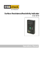
The ETS Model 8873, shown in Figure 1.0-1 is an accurate,
battery-powered, microcomputer-based instrument that meets the
requirements for measuring resistance from 10
2
-10
12
Ohms using
selectable regulated test voltages of 10 or 100V. It is available as
a stand-alone meter for use with external probes or with the
optional plug-in, 2.5” dia. solid electrode/concentric ring electrode
assembly. Also available is the Model 8873 Test Kit that includes
the Model 8873 Meter, electrode assembly, 4” dia. conductive
and acrylic test beds, cables and spare batteries plus a Model
850, 5 lb Surface Resistance Probe housed in a dust/waterproof
carrying case. An optional external universal voltage power
module is available for continuous operation of the Model 8873
without draining the batteries. Also available is an ETS Model

3
5646 Humidity/Temperature Indicator for measuring the
environmental conditions where the testing is being performed
Model 8873 with optional electrode assembly
Kit shown with optional Power Module and Hum/Temp Indicator.
Figure 1.0-1: Model 8873 Configurations

4
2.0 DESCRIPTION
The Model 8873 Wide Range Resistance Meter is an accurate,
easy to use instrument. The standard Meter features manual
on/off plus auto standby (internally selectable) and a momentary
PUSH TO TEST button for making a measurement. The voltage
at which the measurement is taken is selected using a push-push
TEST VOLTAGE select button. The 2-line alphanumeric LCD
readout displays the measured resistance plus a flashing * on the
top line and the test voltage (V
e
=10 or 100V) on the bottom line.
The flashing * indicates a measurement is being made. It stops
flashing when the measurement is complete. If V
e
=100V is used,
it is also turned off at this time. Resistance is displayed in
engineering units (ex: 6.35e+8= 6.35x10
8
Ohms) plus
UNDERSCALE and OVERSCALE indication. The lowest
measurable resistance is 100 Ω at 10V and 10 kΩ at 100V. The
highest measurable resistance is approximately 100 GΩ at 10V
and 1 TΩ at 100V. The electrification time required to take a
measurement at the highest resistance is normally less than 15
seconds when the integrated electrode assembly is used.
Measurement accuracy is as follows:
±5% (10
2
to 10
10
Ω @10V
±5% (10
4
to 10
11
Ω @100V)
±15% (>10
10
@10V, >10
11
@100V)
When external test probes are used the electrification time will
increase as a function of the test lead, probe and sample
capacitance. External probes are connected to the Model 8873
via standard banana jacks located on the side of the instrument.
Refer to available ETS Series 800 Resistance/Resistivity Probes
literature sheets for probes to meet virtually any surface, volume
(solids, liquids and powders) and point-to-point resistance
measurement requirement. Other probes having standard banana
plug leads may also be used. When using external probes the
integrated electrode assembly must either be removed or the
Meter must be placed on an insulated surface (resistance >10
12
Ω).

5
The auto shutoff feature places the unit in “sleep” mode if no
activity is detected after approximately 15 minutes. To perform a
test, simply depress the PUSH TO TEST button and the unit will
“wake up”. When not being used the instrument should be
completely turned off using the POWER switch. For applications
where this feature is not required an internal switch disables the
time-out and power on/off will be totally controlled by the POWER
switch To access this switch remove the outer shell (see
changing batteries) It is located left of the POWER switch. When
battery voltage is low the display automatically displays Low
Battery.
3.0 OPERATION
To make a measurement using the integrated electrode select the
appropriate electrode configuration, depress the push-push
POWER button. The LCD will indicate PUSH TO TEST and the
test voltage selected. Place the Model 8873 on the surface to be
measured and press the PUSH TO TEST button momentarily.
The * will flash and measurements will be indicated until a stable
reading is obtained, usually within 5 seconds. The * will stop
flashing and the final measurement will be displayed for 60
seconds or until another test is initiated. The solid 2.5” (6.35 cm)
electrode is used to measure point-point resistance and
resistance to ground (RTG). The concentric rings are used to
measure surface resistance per ESDS STM 11.11. When
applicable, the resistance measurement can be converted to
surface resistivity per ASTM D 257 by multiplying the measured
resistance by 10 (ρ
s
=10R
m
Ohms/sq).
Volume resistance can be measured between the 2.5” dia.
electrode and the conductive test bed (included in the Model 8873
Kit). Note: The center electrode of the concentric ring cannot be
used for this measurement because the outer V
e
electrode is
always connected. If the test sample is less than 2.5” in diameter
and does not make contact with the outer ring then the center
electrode can be used to make a volume resistance

6
measurement per STM 11.12. To measure per STM 11.12 an
external probe must be used.
To make a volume resistance measurement connect the
conductive test bed to the V
e
output (Red) located on the side of
the instrument. Place the planar material to be tested on the
conductive plate and then place the instrument on top of the
material. Momentarily press the PUSH TO TEST button and wait
until a stable reading is obtained. To convert a volume resistance
measurement to volume resistivity, multiply the reading by 31.7
(the area of the 2.5” electrode in cm
2
) and divide by the thickness
of the sample in cm (ρ
v
=31.7/t Ohms-cm). If the center electrode
is used (STM 11.12) then use 7.1 instead of 31.7.
The electrode assembly is connected to the measuring unit by 3
banana jacks. Thumbscrews (one for each electrode
configuration) are located on the side of the assembly to lock it in
place. To measure point-to-point resistance or RTG insert the
electrode assembly into the banana jacks with the 2.5” electrode
facing out. Plug an ETS Model 850, 845 or equivalent probe into
the V
e
(Red) jack. To measure pt-pt resistance place both the
Meter and the external probe onto the surface to be measured.
To measure RTG connect the supplied red wire from the V
e
jack
to the desired ground point using either the banana plug or the
alligator clip adapter supplied. Refer to Figure 3.0-1 for RTG and
pt-pt connections.

7
Figure 3.0-1: RTG and pt-pt connections
Place the instrument firmly on the test surface and perform the test
as described above. Since the 5-pound weight of the Model 8873
provides the specified contact pressure, no additional pressure
should have to be applied.
When using external probes, remove the electrode assembly, if
provided, and plug the probes into the external Red V
e
and Black
SENSE banana jacks. Follow the instructions for measuring with
the respective external probes. Figure 3.0-2 shows the connection
of an ETS Model 844 2-Point Probe.
Connect to
Red
V
e
Jack
Connect to
Red
V
e
Jack

8
Figure 3.0-2: External Probe Connections
4.0 MEASUREMENT CONSIDERATIONS
4.1 Resistance
For most film and foam materials the standard 5- pound
weight of the Model 8873 Wide Range Resistance Meter is
sufficient for the electrodes to make total contact with the
material surface. However, for rigid materials such as work
surfaces, plastics, cardboard, etc, additional force, which
will have to be determined by the user, may have to be
applied to the Meter to ensure total electrode contact.
Microscopically, these surfaces are generally not smooth
and are uneven as illustrated in Figure 4.0-1.

9
Figure 4.0-1: Microscopic Electrode/Rigid Surface Contact
In most cases the application of additional pressure will
cause the measured resistance reading to decrease. This
is a result of both lower contact resistance and total
electrode/surface contact area (greater number of parallel
resistance paths). Optimum contact pressure is obtained
when the resistance measurement is stable.
Another area that must be considered when attempting to
measure surface resistance is the composition of the
material being evaluated. ANSI/ASTM D-257, a widely
used test standard, is specified for homogeneous,
insulating material.
However, many materials are either not homogeneous,
relatively conductive and in the case of some composite
material, nonlinear. For these materials a surface
resistance measurement in accordance with ESD
STM11.11 must be used.
For example, the surface resistance of bulk loaded
materials have relatively low volume resistance and cannot
easily be measured because the volume and surface
resistance become part of the measurement. The current
path between the electrodes is not only across the top
surface but also through the material.

10
Similarly, the surface resistance of materials that are
coated with, or laminated to, a conductive surface must
also be measured using STM11.11. The surface
resistance may actually be very high, but the volume
resistance may be significantly lower. Therefore, the
measured resistance may be that of the surface resistance
path between the electrodes in parallel with the series
combination of the two volume conductive paths and the
conductive layer as shown in Figure 4.0-2.
Figure 4.0-2: Multiple resistance paths of laminated material
Composite materials are very difficult to measure. They
usually consist of a plastic resin filler with very high
resistance properties loaded with a small percentage of a
conductive material such as carbon powder, fibers or
utilize nanotube technology. When molded these parts
exhibit either conductive or static dissipative properties as
defined in the ESD ADV1.0: Glossary of Terms. These
materials have bulk resistance properties verses the
surface only resistance properties found in other ESD
materials. When a voltage is applied either across or
through the material the dielectric of the filler breaks down
and current flows from particle to particle. As the loading of
the conductive medium decreases there is greater
distance between particles that require a higher voltage to
break down the increased dielectric. At some point, once a
higher voltage is applied to establish continuity the

11
resistance path created may become altered permanently.
It should be noted that loaded thermoplastic materials is
only effective in reducing the upper resistance limit to
approximately 10
8
Ohms.
Another characteristic of loaded thermoplastic materials
that affects the resistance measurement is the microscopic
insulative layer that develops on the surface of the molded
part. The dielectric of this layer must be broken down
before a resistance measurement can be made. Once this
occurs the actual resistance of the part may be lower than
the measuring range of the instrumentation used.
Essentially, these materials are non-linear and voltage
dependent. Different test voltages will give different results.
Even the series resistor incorporated in virtually all
resistance meters vary from meter to meter and can cause
measurement variations. When measuring these materials
the initial measurement should be always be made first at
V
e
= 10V then at 100V.
Another very important consideration in measuring surface
resistance is the time of electrification. This is the time for
the effective capacitance of the material to charge up. At
this time, the current flow through the material reaches
steady state and its flow is then a function of only the
resistance of the material.
Effective material capacitance is generally quite low. For
low resistance materials, the RC time constant, τ, is very
short. On the other hand, for very high resistance materials
the time constant can become quite long. When using the
Model 8873 the overall capacitance of the system is
relatively low so an electrification time of only 5-15
seconds is required to measure the maximum resistance.
For material in the static dissipative range the
electrification time is usually less than 5 seconds.
Resistances that are measured before the full time of

12
electrification has occurred will appear to be lower than the
actual resistance of the surface. This difference can be
several orders of magnitude. ASTM D 257 recommends a
time of electrification of 60 seconds, but in many
measurements a shorter time may be used or a longer
time may be required. Typically for small sample
specimens with resistances less than 10
12
ohms, the of 5
to 15 second electrification time is sufficient. On the other
hand, large surfaces such as table tops, floors etc. the
capacitance is relatively large and 60 seconds may not be
long enough. Here, the user may either wait for complete
electrification to obtain a true resistance measurement or
specify the measurement at the 60 second electrification
time point for a relative resistance measurement. A rule of
thumb, “When in doubt, allow more rather than less time!”
4.2 RESISTANCE CHARACTERIZATION
Over the years many different resistivity or resistance values have
been assigned to designate the various classifications of ESD
material. Surface resistivity per ASTM D257 was the most
common specification used to classify materials. However, this
specification is for insulating materials and when the bulk
characteristics of the material come into play significant errors are
introduced. This became apparent during packaging material
specification development approximately 15 years ago. It was
found that by specifying all test parameters measurement
variations between laboratories testing the same material was
reduced from 3 orders of magnitude to better than one-half order
of magnitude. Since all measurement parameters were now
specified it was no longer necessary to specify the measured
resistance readings in Ohms/square since the electrode
configuration factor was no longer required. Therefore, all ESD
resistance values are now specified in Ohms. This is covered in
ESDS STM 11.11, 11.12 and 11.13 for surface, volume
resistance and 2-point measurements respectively.

13
Currently ESD materials are classified as follows:
Conductive Dissipative Insulative
Surface <10
4
10
4
to <10
11
≥10
11
Ω
Volume same same
Materials with bulk resistance characteristics can also be
classified by specifying its volume resistivity. This is simply done
by multiplying the measured resistance by the area of the
measuring electrode or material surface, whichever is smaller,
and divided by the thickness. All values are in cm giving a volume
resistivity in Ohms-cm. To convert to Ohms-meter, multiply by
100.
Increasing or decreasing the thickness of the material will also
change the actual resistance of the part with a specified volume
resistivity. This is a common technique used in ESD products to
achieve a particular resistance. It is the actual resistance of the
part, not its resistivity that determines how a part dissipates a
static charge.
While the above resistance classifications were developed for
ESD packaging materials many specifications used for other
applications that specify material resistance/resistivity refer to
these resistance limits.
It should be noted that the resistance/resistivity property of
material does not predict whether the material will be low
charging (antistatic) or not.
4.3 Measurement Documentation
When certifying material it is best to do it under controlled
environmental conditions. Since lower humidity can affect the
material resistance properties all certification tests should be
prepared and performed at 12% RH and 23°C as specified in

14
ESD STM 11.11 & 11.12. Since current plastics industry
standards specify standard conditions at 50% RH, 23
°
C
certification should also be performed at these conditions
also to allow comparison of existing data.
For testing components and assemblies a controlled environment
may not be practical. Under these conditions the humidity and
temperature should be recorded at the time of testing. (Refer to
the optional ETS Model 5646 Humidity/Temperature Indicator.)
The following procedure should be followed when measuring and
documenting resistance measurements:
1. Sample preparation
2. Test instrumentation including setup and system verification
tests.
For loaded thermoformed material the test instrumentation,
electrodes and system verification are critical in obtaining
multi-lab correlation and must be specified.
3. A defined electrification period (measuring time).
When measuring very high resistance the RC time
constant of the sample and the instrumentation may
require a significant amount of time for the test voltage to
completely develop across the sample. The electrification
time may be different for different instruments. Hence,
measuring a known resistor at the upper limit will enable
the user to determine the time it takes to measure the
correct value.
Some materials may exhibit a change in resistance during
measurement. Taking measurements at a fixed time
minimizes this problem.
4. Test procedure
The test procedure is extremely important. How the sample
is prepared, test electrodes, how the instrumentation is

15
connected, test voltages used and how the measurement
is taken all affect the ultimate accuracy of the data.
5. Documentation and reporting of data.
Complete documentation of the measurements is
essential. The level of data processing is a function of the
end user requirements.
5.0 EXTERNAL POWER MODULE
An optional universal power module that operates from 90-
260VAC, 50/60Hz power (Mains) is available. It plugs into the
5mm jack located between the auxiliary probe jacks. When
plugged in, the internal batteries are disconnected. When using
this module, the unit must be connected to ground.
Plug one end of the green ground cable into the hole in the
base marked with the ground symbol as shown in Figure 5.0-
1 and connect the other end to house ground.
Figure 5.0-1: Optional Power Module connections

16
6.0 MAINTENANCE
The Model 8873 has no user serviceable parts except changing
the batteries. It must be returned to ETS for service. Contact ETS
Calibration Department at 215-887-2196 to obtain a Return
Material Authorization (RMA) for all warranty, service and
calibration.
The user can check the calibration of the Meter by measuring the
resistance of precision resistors over the measurement range of
the instrument.
To change batteries remove the 3 black thumbscrews securing
the outer shell to the base. Lift off the shell and slide the batteries
out of the recess. Replace batteries as a pair. Use only 9-Volt
alkaline or other high capacity batteries for best performance.
6/08

17
7.0 WARRANTY
Electro-Tech Systems, Inc. warrants its equipment, accessories and parts of its
manufacture to be and remain free from defects in material and workmanship
for a period of one (1) year from date of invoice and will, at the discretion of
Seller, either replace or repair without charge, F.O.B. Glenside, similar
equipment or a similar part to replace any equipment or part of its manufacture
which, within the above stated time, is proved to have been defective at the
time it was sold. All equipment claimed defective must be returned properly
identified to the Seller (or presented to one of its agents for inspection). This
warranty only applies to equipment operated in accordance with Seller's
operating instructions.
Seller's warranty with respect to those parts of the equipment which are
purchased from other manufacturers shall be subject only to that
manufacturer's warranty.
The Seller's liability hereunder is expressly limited to repairing or replacing any
parts of the equipment manufactured by the manufacturer and found to have
been defective. The Seller shall not be liable for damage resulting or claimed to
result from any cause whatsoever.
This warranty becomes null and void should the equipment, or any part
thereof, be abused or modified by the customer of if used in any application
other than that for which it was intended. This warranty to replace or repair is
the only warranty, either expressed or implied or provided by law, and is in lieu
of all other warranties and the Seller denies any other promise, guarantee, or
warranty with respect to the equipment or accessories and, in particular, as to
its or their suitability for the purposes of the buyer or its or their performance,
either quantitatively or qualitatively or as to the products which it may produce
and the buyer is expected to expressly waive rights to any warranty other than
that stated herein.
ETS must be notified before any equipment is returned for repair. ETS will
issue an RMA (Return Material Authorization) number for return of equipment.
Equipment should be shipped prepaid and insured in the original packaging. If
the original packaging is not available, the equipment must be packed in a
sufficiently large box (or boxes if applicable) of double wall construction with
substantial packing around all sides. The RMA number, description of the
problem along with the contact name and telephone number must be included
in formal paperwork and enclosed with the instrument. Round trip freight and
related charges are the owner’s responsibility.
/