
SAE J1645 TEST KIT
Model 2004
Operating Manual
9/08

2

1.0 INTRODUCTION
The Model 204 Charged Plate Analyzer is a fully functional charged plate
monitor that combines the ETS Model 212 Static Meter with a ±1200V low
current power supply, timing circuit and a removable charged plate detector. The
Model 2004 J1645 Test Kit contains the necessary accessories that provide a
convenient and economical approach to performing electrostatic measurements
requiring a charged plate monitor. The Model 204 meets the requirements of
ESD STM3.1-2000, Ionization and ESD SP3.3-2000 Periodic Verification of Air
Ionizers, SAE 1645 plus most other specifications requiring a charged plate
monitor.
The standard Model 204 has a 60 second timer, however, when used to test the
dissipation time of automotive fuel system components as specified in SAE
J1645 the optional 6 second timer version is provided.
Typical charged plate tests that can be performed with the Model 2004 Kit are
measuring ionizer balance and neutralization time, static propensity of floors and
footwear, triboelectric charge evaluation of material, static dissipation plus
evaluation of the effectiveness of personnel grounding systems. In addition,
removing the detachable charged plate detector from the Model 204 converts it
to an electrostatic fieldmeter.
1.1 SAEJ1645 Test Kit
The standard Kit consists of the following instruments and accessories:
1. Model 204 Charged Plate Analyzer
2. Model 880 Autoranging Resistance Indicator
3. Model 256 Utility Wiring Verifier with electrical ground banana jack
(North American Std only. Omitted in kits destined for locations
using 220-240 VAC.)
4. Tripod
5. 10’ coiled ground cord with clip
6. Model 5646A Humidity/Temperature/Dew Point Indicator
7. Model 832 Clamp Electrodes
8. Grounding Relay Module
9. 30” (76cm) Red & Black cables with plug-in alligator clips
Kit is housed in a ABS carry case with foam insert measuring
13.5”Wx10”Dx4.5”H (343x245x114mm)
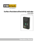
2.0 EQUIPMENT DESCRIPTION
This section provides a detailed description of each of the instruments and
adaptors included in the Model 2004 SAE J1645 Test Kit.
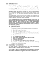
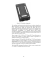
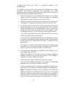
The Kit shown in Figure 2-1 is specifically designed to measure the resistance
and dissipation characteristics of automotive fuel systems as specified in SAE
1

2
J1645, but can be used wherever any of these parameters need to be
measured.
The included tripod is used to hold the Model 204 in either a vertical or
horizontal position to facilitate) measurements.
Figure 2-1: Model 2004 SAE J1645 Test Kit
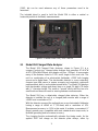
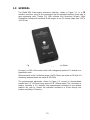
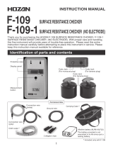
2.1 Model 204 Charged Plate Analyzer
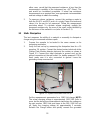
The Model 204 Charged Plate Analyzer, shown in Figure 2-2, is a
compact “pocket size” charged plate analyzer that measures 8”Lx2.4”W
x0.9”H (203x146x229mm) and weighs only 9oz. (255gm). It incorporates
many of the features found in CPA’s much larger in size and cost. The
unit is a combination of an electrostatic fieldmeter, ±1200 Volt charging
source and a digital timer. The electrostatic detector is a non-contacting,
chopper type field sensor to ensure accurate and consistent continuous
measurements both in and outside ionized fields. The Model 204 displays
both electrostatic voltage and decay time on a single 3½-digit LCD meter
with ½” character height. The meter is “zeroed” easily with the turn of a
small knob and does not need re-zeroing between measurements.
The Model 204 has a detachable charged plate detector. When the
detector is installed the unit is a charged plate monitor with a range of
±2000V and a resolution of 1V.
With the detector removed the unit performs as an electrostatic fieldmeter
having a range of ±20kV at 1” (25.4mm) with a resolution of 10V.
Measurement accuracy is ±10% in this mode. It includes a convenient ¼”
(6mm) ground snap, compatible with most standard wrist strap cords, to
facilitate grounding and to increase accuracy.
The charging function automatically activates the timing mode. As the
applied 1200 Volt charge on the detector plate decays, either by

3
ionization or by dissipation through a resistance. The timer starts when
the measured voltage drops to 1000 Volts and stops when it decays to
100 Volts. Decay times to 6 sec. in 0.03 sec. increments can be
measured.
The 3½-digit LCD meter displays the voltage, polarity, or dissipation time
when the decay function of the Analyzer is used.
The Model 204 operates from a single 9V alkaline battery with a typical
operating life of approximately 20 hours. Low battery is indicated by all
decimal points illuminated on the DPM.
Figure 2-2: Model 204 Charged Plate Analyzer
2.1.1 Charged Plate Detector
The Charged Plate Detector converts the Model 204 to a charged
plate monitor having the specified 20pf (ESD S3.1) capacitance
with both the 2.5”x1” (161x25mm) detector plate and the optional
6”x6” (152x152mm) standard size plate. When installed, the
detector plate contacts the charging source and the sensitivity of
the measurement system is increased by a factor of 10. After + or -
V is applied, the system automatically converts to a timer when the
voltage on the plate drops to 1000V, within the range of 0-6

4
seconds with 0.03 seconds resolution. It then measures the time
for the charge on the plate to bleed down to 100V at which time
the DPM switches over from a voltage display to a time display. If
the charging source is not activated then the instrument just
measures the detected voltage generated by ionizer imbalance,
static propensity, or any charged object placed onto the charged
plate. The optional 6”x6” (152x152mm) square detector plate plugs
into the Model 205C detector plate to provide full size charged
plate monitor capability. The maximum current output of the
charging source is limited to 1 μAmp.
2.2 Model 256 Utility Wiring Verifier
This device plugs into a standard (North American) 110 VAC outlet and
checks both the wiring of the outlet and provides a convenient standard
banana jack output to access electrical ground. This device is not
included in kits destined for locations using 220-240 VAC.
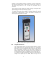
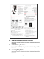
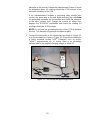
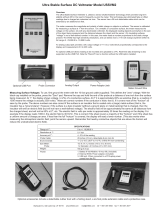
2.3 Model 5646A Humidity/Temperature/Dew Point Indicator
The Model 5646A enables the user to establish the humidity and
temperature at the time of test as required by most specifications. The
Indicator measures relative humidity over the range of 5-95% RH with an
accuracy of ±3% RH and temperature over the range of 32 to 122°F (-20
to +70°C) with an accuracy of ±0.9°F (0.5°C). °F or °C can be selected
and the dew point automatically calculated and displayed at the press of
a button. The Model 5646A operates from 3 standard 1.5V AAA batteries.
Refer to Figure 2-3 for the Model 5646A Operating Instructions.

5
Figure 2-3: Model 5646A Operating Instructions
2.4 Model 880 Autoranging Resistance Indicator
Refer to the Model 880 Operating Instructions included as Appendix A to
this manual.
2.5 Model 232 Clamp Electrodes
Refer to the Model 232 Operating Instructions included as Appendix B to
this manual.
2.6 Grounding Relay Module
Refer to the Model 232 Operating Instructions included as Appendix B to
this manual.

6
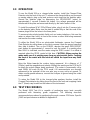
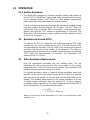
3.0 OPERATION
To use the Model 204 as a charged plate monitor, install the Charged Plate
Detector onto the front of the unit. To measure the charge build-up on personnel
or moving objects, plug a clip lead, probe or wrist strap into the detector plate.
Ground the detector plate by depressing the ZERO/RESET button for
approximately 1 second. Release the button. Any voltage generated will be
transferred to the plate and measured directly by the static meter in Volts.
To install the optional 6”x6” (152x152mm) plate, plug it into the 2 banana jacks
on the detector plate. Make sure the plate is seated fully so that the ends of the
banana plugs fit into the holes in the lower plate.
To measure induced electrostatic fields such as ionizer imbalance, first zero the
meter as above then hold it in front of the ionizer or other field being measured
and monitor the meter reading.
To utilize the Model 204 as an electrostatic fieldmeter, remove the Charged
Plate Detector by pulling down on the tab to unsnap it from the ground snap and
then slide it forward. Turn on the POWER, depress the green ZERO/RESET
push button for approximately 1 second to zero the meter. If a reading other
than 000±2 is indicated, zero the meter using the ZERO control. If an offset is
required adjust the ZERO control at this time. CAUTION: When zeroing the
meter make sure it is pointing away from any electrostatic fields. Covering
the front of the meter with the hand will shield the input from any fields
present.
Bring the Meter towards the surface being measured. At a distance of 1”
(25mm), read the magnitude and polarity. Multiply the reading on the DPM by 10
to obtain the actual voltage being measured. (The meter is permanently set to
read 2000V full scale for the CPM mode.) All measurements are normally
referenced to the potential of the user who may or may not be at ground. To
obtain a solid ground reference, connect the Analyzer to ground using the coiled
cord provided.
To return the Model 204 to the charged plate analyzer function, install the
Charged Plate detector by sliding it over the front of the unit and snapping it onto
the ¼” (6mm) snap located on the bottom of the instrument.
4.0 TEST PROCEDURES
The Model 2004 Test Kit is capable of performing many tests normally
performed with laboratory grade equipment. The following describes
recommended procedures for performing the most common CPM tests. Specific
J1645 test procedures are detailed in Appendix B.

7
4.1 Static Dissipation of Fuel system Components per SAE
J1645
This test is described in detail along with pictures of the specific system
hook-up in Appendix B. It is similar to the measurement of dissipation
time of material and objects described in Section 4.5 below.
4.2 Ionizer Balance
This test is performed with either the Charged Plate detector attached or
with the addition of the optional 6”x6” (152x152mm) detector plate. Turn
on the ionizer. Hold the Analyzer approximately 12“ (305mm) in front of
the ionizer. Momentarily ground the detector plate by touching it with a
finger or a grounded lead. Make sure the DPM reads zero. Observe the
meter reading for approximately 15 seconds. The meter should typically
read less than ±30 Volts or whatever maximum balance limit is specified.
4.3 Static Propensity
This test is the measurement of static charge build-up on personnel
walking across a floor or performing a defined step test. It is used to
evaluate flooring and footwear. However, this test procedure also applies
to any activity that results in a static charge being generated.
The test set up consists of the Model 204 with the Detector attached.
Connect either a wrist strap or a cable with probe. The test subject puts
on the wrist strap or grasps the probe. The tripod can be used to hold the
instrument.
Before starting the test, both the test subject and meter should be
momentarily grounded. The voltage displayed on the meter will be the
voltage generated by the test subject during the activity.
4.4 Triboelectric Charge Analysis
This test uses the Charged Plate Detector plus the 6”x6” (152x152mm)
detector plate. The assembly is mounted onto the tripod with the plate in
the horizontal position. Momentarily ground the detector plate. Take the
material being tested and rub it with an appropriate second material.
Place the test material on the detector plate. The voltage measured is a
relative indication of the antistatic characteristics of the material.
The test procedure can also be used to measure the build-up of static
charge on material, objects, liquids and powders in motion by connecting
the appropriate probes or test leads from the object or isolated detector
(for powders and liquids in a contained environment) to the detector plate.
4.5 Static Dissipation of Material and Objects
The built-in timer is activated only when the CHARGE button is
depressed and then it only measures dissipation time from 1000 to 100V
up to 6 seconds. For measurements that do not require the application of

8
voltage (Triboelectrically charged material, for example), having voltage
levels less than 1000V or having dissipation times greater than 6 seconds
the timer cannot be used. An external timing device such as an
oscilloscope or chart recorder connected to the RECORDER output or a
stopwatch will be required.
If the decay time is less than 6 seconds and the sample can be
conductively charged by the charging source then the internal timer can
be used.
If longer decay times are required (>6 sec.) then the standard 60
second version with 0.3 second resolution should be used.
To measure the decay time of the sample, after being grounded is
desired first place the charged sample on the detector plate, then
connect a ground lead to the sample, NOT TO THE PLATE.
To measure the decay time of a sample that is either conductive or
dissipative, place it on the detector plate. Charge it by depressing the
CHARGE button and holding it for several seconds to ensure the sample
is charged to the full voltage. Connect a ground lead to the sample. The
Analyzer will measure the time for the detector plate and sample to
dissipate its charge.
Another dissipation test is to charge the detector plate and then place a
grounded sample on the plate and measure the time for the plate to
dissipate its charge through the sample.
4.6 Charge Neutralization Time
This test measures the time for an ionizer to neutralize a charge on an
object. It is also referred to as "Discharge Time". This test can be
performed with either the standard detector or with the optional 6”x6”
(152x152mm) plate.
Turn on the ionizer and allow it to run long enough to stabilize. Hold the
Analyzer 12” (305mm) or other specified distance away from the front of
the ionizer. Momentarily ground the detector plate then depress either the
+ or – CHARGE button. The red LED indicator will light and the plate will
charge up to approximately 1150 Volts. Release the CHARGE button.
The ionizer will immediately start to neutralize the charge on the plate.
When the charge drops to 1000V the built-in timer starts and the unit will
start measuring the time for the charge on the plate to bleed down to
100V. When the voltage on the plate reaches 100V the meter switches
over from reading voltage to reading time as indicated by the yellow
“TIME-SEC” LED. Depressing the ZERO/RESET pushbutton grounds the
detector plate and resets the timer.
4.7 Static Dissipation of Personnel
This test measures the time it takes a charged person to bleed off the
charge when a static control procedure is implemented such as stepping

9
onto a conductive floor or sitting down in a conductive chair. The test
subject is connected to the detector plate using a wrist strap or a probe
assembly plugged into the front of the detector plate.
Momentarily ground the detector plate and test subject. Depress the
CHARGE button to charge both plate and test subject. The meter should
indicate a reading of approximately 1150V. The test subject must be
standing on an insulated surface during charging. The test subject should
then immediately step onto the surface being evaluated. The Analyzer will
measure the time for the voltage on the test subject to bleed down to
100V.
5.0 Calibration
The Model 204 is a complex instrument. It is recommended that it be calibrated
at the factory.
However, the customer can check the voltage reading calibration by applying a
known voltage, such as 500 or 1000V directly to the detector plate and compare
it with the meter reading. If out of tolerance, the Charged Plate Detector
Assembly can be moved slightly in to increase or out to decrease the meter
reading.
6.0 MAINTENANCE
The Model 204 Charged Plate Analyzer and the respective kits contain both
electronic instruments (Charged Plate Analyzer and Humidity/Temperature/Dew
Point Indicator) plus mechanical fixtures (Charged Plate Detector, 6”x6”
[152x152mm] Detector Plate (optional) and tripod). As with all instrumentation,
care should be exercised in handling and using the equipment. If not exposed to
hostile environments, the mechanical fixtures should not require any
maintenance. To clean the fixture, wipe with only isopropyl alcohol using a soft
lint-free cloth and let air-dry.
DO NOT USE ANY OTHER TYPE CLEANER AS THIS WILL PRODUCE A
LEAKAGE PATH TO THE ISOLATED CHARGED PLATE.
When used with reasonable care, the instruments should provide many years of
trouble-free service. If either electronic unit fails to operate properly, first check
the battery. The sensors, both static and humidity/temperature, should never be
touched by a charged object or by personnel. Also, the sensors could be
permanently damaged if the instruments are dropped.
Note:
The sensor used in the Model 204 is very sensitive to shock. Dropping the
unit could result in permanent damage to the sensor and will require
replacement.

10
To clean the conductive ABS plastic case, a damp cloth should be used. Do not
use any solvents as these may react with the plastic and damage the case.
The Model 5646A Humidity/Temperature/Dew Point Indicator does not contain
any user serviceable parts and must be returned to the factory for service or
replacement.
7.0 SPECIFICATIONS
FIELDMETER/POWER SUPPLY CHARGED PLATE DETECTOR
Sensor: Vibrating Reed Capacitance: 20±3pf
Range: ±20 kV @ 1” (25.4mm) Detector Plate: 1”x3” (2.5x7.6cm)
Display: 3 ½-Digit LCD Plug-in option:.6”x6” (152x152mm)
Resolution: 1V (10V as a Fieldmeter) Accuracy: ±20%
Accuracy: ±10% (Fieldmeter) Ground:
Linearity: ±10% Cord: 10’ (3m)
HVPS: ±1200V (approx) Connection: ¼” (6mm) Male Snap
Timer: 0-60 sec. (0-6 sec. optional)
Accuracy: 5% of Reading
MECHANICAL
Resolution: 0.3 sec. (0.03 sec.) Dimensions: 8”Lx2.4”Wx0.9”H (203x146x229mm)
Rec. Out: Weight: 9 oz. (255gm)
2.5 mm Jack Case: Conductive
Signal: 10 mV/kV (200mV FS)
Power: 9V Battery
Life: 20 Hrs. typical.
Bat Low: All decimal pts. Illuminated
9/08

11
8.0 WARRANTY
Electro-Tech Systems, Inc. warrants its equipment, accessories and parts of its
manufacture to be and remain free from defects in material and workmanship for
a period of one (1) year from date of invoice and will, at the discretion of Seller,
either replace or repair without charge, F.O.B. Glenside, similar equipment or a
similar part to replace any equipment or part of its manufacture which, within the
above stated time, is proved to have been defective at the time it was sold. All
equipment claimed defective must be returned properly identified to the Seller
(or presented to one of its agents for inspection). This warranty only applies to
equipment operated in accordance with Seller's operating instructions.
Seller's warranty with respect to those parts of the equipment that are
purchased from other manufacturers shall be subject only to that manufacturer's
warranty.
The Seller's liability hereunder is expressly limited to repairing or replacing any
parts of the equipment manufactured by the manufacturer and found to have
been defective. The Seller shall not be liable for damage resulting or claimed to
result from any cause whatsoever.
This warranty becomes null and void should the equipment, or any part thereof,
be abused or modified by the customer of if used in any application other than
that for which it was intended. This warranty to replace or repair is the only
warranty, either expressed or implied or provided by law, and is in lieu of all
other warranties and the Seller denies any other promise, guarantee, or
warranty with respect to the equipment or accessories and, in particular, as to its
or their suitability for the purposes of the buyer or its or their performance, either
quantitatively or qualitatively or as to the products which it may produce and the
buyer is expected to expressly waive rights to any warranty other than that
stated herein.
ETS must be notified before any equipment is returned for repair. ETS will issue
an RMA (Return Material Authorization) number for return of equipment.
Equipment should be shipped prepaid and insured in the original packaging. If
the original packaging is not available, the equipment must be packed in a
sufficiently large box (or boxes if applicable) of double wall construction with
substantial packing around all sides. The RMA number, description of the
problem along with the contact name and telephone number must be included in
formal paperwork and enclosed with the instrument. Round trip freight and
related charges are the owner’s responsibility.

12
Appendix A
AUTORANGING RESISTANCE
INDICATOR
MODEL 880
OPERATING INSTRUCTIONS
9/08

13
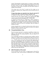
1.0 GENERAL
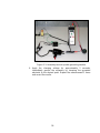
The Model 880 Autoranging resistance Indicator, shown in Figure 1-1, is a CE
certified, precision, easy to use instrument that incorporates features found only in
more expensive units. Twelve (12) LEDs indicate the Conductive (Green), Static
Dissipative (Yellow) and Insulative (Red) ranges in one (1) decade steps from <10
3
to
>10
12
Ohms.
Figure 1-1: Model 880 Autoranging resistance Meter
Accuracy is ±10% of the mean value, with changeover points of ½ decade on a
logarithmic scale.
Measurements in the Conductive range (<5x10
5
Ohms) are made at 10 Volts. All
remaining measurements are made at 100 Volts.
The measurement electrodes, shown in Figure 1-2, consist of chrome-plated
parallel bars 2.5” (62.5mm) long, spaced 1.56” (40mm) apart. The conversion to
surface resistivity is 1.6, however, the measurement resolution of one decade
enables the user to convert the indicated resistance in Ohms directly into
surface resistivity in Ohms/sq.

14
Figure 1-2: Electrode configuration
Two auxiliary input banana jacks enable the user to plug in virtually any
type of resistance measurement electrode having cables with standard
0.161” (4mm) banana plugs that converts the Model 880 to an
independent wide range resistance indicator. When the auxiliary probe
banana plug is inserted the built-in parallel bar electrodes are
automatically disconnected. The supplied ground cable enables
resistance-to-ground (RTG) measurements to be made by disconnecting
one of the parallel bar electrodes and using the other parallel bar as the
surface electrode for quick checks.
When testing to SAE J1645 the ETS Model 832 Clamp Electrodes are
used and are included in the Model 2004 Kit. Refer to Appendix B for
additional instructions for using the clamps.
Using the optional ETS Model 850, 5lb (2.27kg), 2.5” (63.5mm) diameter
Surface Resistance Probe(s) standard RTG and point-to-point resistance
measurements can be made. Volume resistance, seating resistance per
ESDA STM12.1 or other resistance measurements using the appropriate
electrode configuration can also be made with the Model 880.
The Model 880 Autoranging Resistance Indicator comes complete with
RTG cable, 9 Volt battery and vinyl carry case.

15
2.1 OPERATION
2.1.1 Surface Resistance
The Model 880 is designed to measure samples having a flat surface at
least 2.5”x1.75” (64x45mm). The sample being tested should be placed
on an insulated surface (>10
13
Ohms) to avoid parallel measurement
paths, especially if the material has any bulk resistance.
Prior to making measurements first check the Indicator by holding it away
from any surface and pressing the TEST button. The >10
12
Red LED
should light. Place the Model 880 on the surface to be measured, then
depress and hold the TEST button for approximately 3-5 seconds. The
illuminated LED indicates the surface resistance of the material in Ohms
or Ohms/sq., if desired.
2.2 Resistance-to-Ground (RTG)
To measure the RTG of a table top, mat or flooring plug the RTG cable
supplied into one of the auxiliary banana jacks. This will disconnect the
corresponding bar electrode. Clip the cable to the common point ground
and place the Indicator on the surface to be measured. The other bar
electrode performs the function of a surface probe. Depress and hold the
TEST button for approximately 3-5 seconds. The illuminated LED
indicates the RTG in Ohms.
2.3 Other Resistance Measurements
Plug the appropriate electrodes into the auxiliary jacks. The bar
electrodes will now be disconnected. Place the probe(s) on the surface
being measured. Follow the above test procedure. The illuminated LED
indicates the measurement resistance in Ohms.
For volume resistance, either a standard volume resistance probe and
test bed can be used or just simply connect the RTG cable to a test bed
and then place the sample on the test bed and the Model 880 on the
sample. The resulting measurement is the volume resistance in Ohms.
To obtain volume resistively, place the optional 2.5” (6.45cm) diameter
conductive rubber electrode on top of the sample and the Model 880 on
top of the electrode. The volume resistivity will be
ρ
v
= A/t R
m
= 31.7/t R
m
Ohms-cm
Where A is the area of the electrode in cm
2
and t is the thickness of the
sample in cm.

16
3.0 MAINTENANCE
The Model 880 operates from a standard 9 Volt battery. The momentary nature
of the measurements allows for a very long battery life. When the LEDs appear
dim and/or the measurements are unstable, change the battery.
Remove the four (4) Phillips head screws and carefully remove the bottom
cover. Replace the battery and reinstall the cover.
To clean the instrument, wipe with a clean, damp cloth. Do not use any solvents
as these make react with the plastic case and may damage it.
9/08

17
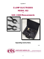
Appendix B
CLAMP ELECTRODES
MODEL 832
Plus
SAE J1645 Measurements
Operating Instructions
9/08

18
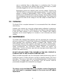
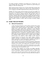
1.0 GENERAL DESCRIPTION
The Model 832 Clamp Electrode Assembly
is designed to test tubes, valves and other
planar and non-planar objects such as IC
Shipping Tubes and Automotive Fuel Line
components and assemblies in
accordance with current and proposed
industry specifications requiring resistance
and/or static dissipation measurements.
The probes feature a unique dual-pad
design capable of measuring point-to-
point, point-to-ground, volume
resistance/resistivity and static dissipation.
The Model 832 meets the electrode
configuration specified for measuring the
resistance of fuel line components and
assemblies in accordance with SAE J1645
(versions dated 9/03 or later).
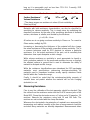
The electrodes are designed to be used with resistance meters having test
voltages of 10 and 100 volts such as the ETS Models 880 and 871 (shown
below) or the Models 8873 and 863-6487. When connected to the detector plate
of a charged plate monitor such as the ETS Model 204 Charge Plated Analyzer,
the electrodes enable the user to measure dissipation time from 1kV to 100
volts, in accordance with SAE J1645.
Model 880 Model 871
2.0 ELECTRODE DESCRIPTION
The Model 832 electrode assembly consists of one .25” square (6mm) and one
.25”x.125” (6x3mm) conductive elastomer pads with volume resistivity of 0.08
ohm-cm and Shore-A hardness of 65 durometer. The pads are mounted to
stainless steel electrodes that in turn are mounted to an insulated clamp exerting
approximately 10 pounds (4.5kg) of force.
Page is loading ...
Page is loading ...
Page is loading ...
Page is loading ...
Page is loading ...
Page is loading ...
Page is loading ...
-
 1
1
-
 2
2
-
 3
3
-
 4
4
-
 5
5
-
 6
6
-
 7
7
-
 8
8
-
 9
9
-
 10
10
-
 11
11
-
 12
12
-
 13
13
-
 14
14
-
 15
15
-
 16
16
-
 17
17
-
 18
18
-
 19
19
-
 20
20
-
 21
21
-
 22
22
-
 23
23
-
 24
24
-
 25
25
-
 26
26
-
 27
27


Ask a question and I''ll find the answer in the document
Finding information in a document is now easier with AI
Related papers
Other documents
-
Myfox TA4006 User manual
-
 Monroe Electronics 288 Specification
-
SEFRAM BK 880 User manual
-
UEi Test Instruments DMEG3 Owner's manual
-
 Prostat ESI-870 User manual
-
 Monroe Electronics 268A User manual
-
 HOZAN F-109 Owner's manual
-
 Bioclimatic PAP SERIES Installation, Operation and Maintenance Manual
-
Sierra Monitor Corporation IZS31 User manual
-
 AlphaLab USSVM2 Operating instructions


