Page is loading ...

MODEL G0620
SUPPLEMENT MANUAL FOR
DIGITAL CONTROLS
COPYRIGHT © MARCH, 2008 BY GRIZZLY INDUSTRIAL, INC.
WARNING: NO PORTION OF THIS MANUAL MAY BE REPRODUCED IN ANY SHAPE
OR FORM WITHOUT THE WRITTEN APPROVAL OF GRIZZLY INDUSTRIAL, INC.
#TR10571 PRINTED IN USA
Fence Controller
Main Control Panel


Table of Contents
INTRODUCTION ............................................... 2
Foreword ........................................................ 2
Contact Info ...................................................
2
MAIN CONTROL PANEL OPERATIONS ........
3
Control Panel Identification ............................
3
Quick Start .....................................................
4
MM/Inch Selection .........................................
5
Scoring Blade
Adjustments ............................ 5
Blade Height
Adjustments ............................. 6
Blade Tilt
Adjustments ................................... 7
Rip Fence
Adjustments .................................. 8
Combining Adjustment Entries ..................... 9
Memory Functions .......................................
10
Blade Diameter Calibration ..........................
11
Blade Height Calibration ..............................
12
Blade Tilt Calibration ....................................
13
Rip Fence Cutting Width
Calibration ........... 14
Rip Fence Thickness
Calibration ................. 15
FENCE OPERATIONS ...................................
16
Control Panel Identification ..........................
16
MM/Inch Selection .......................................
17
Checking Battery .........................................
17
Changing Resolution ...................................
17
Calibrating the Display ................................. 18
Using Offsets ...............................................
19

-2-
G0620 Main Control Panel
INTRODUCTION
Foreword
Both controllers covered in this manual have
capabilities beyond their use with the Model
G0620. For that reason, you may find functions or
features that will never be used with your saw.
Aside from instructional clarity, this manual aims
to filter out the applicable features from the non-
applicable features of these controllers, so you
can quickly understand the functions you need
to get your machine up and running. Also, the
complete factory manual for the controllers are
still included with your machine, in case you need
them.
The specifications, drawings, and photographs
illustrated in this manual are current when the
manual was prepared. However, owing to Grizzly’s
policy of continuous improvement, changes may
be made at any time with no obligation on the
part of Grizzly. For your convenience, we always
keep current Grizzly manuals available on our
website at
www.grizzly.com. Any updates to
your machine will be reflected in these manuals
as soon as they are complete. Visit our site often
to check for the latest updates to this manual!
We stand behind our machines. If you have any
service questions or parts requests, please call or
write us at the location listed below.
Grizzly Industrial, Inc.
1203 Lycoming Mall Circle
Muncy, PA 17756
Phone: (570) 546-9663
Fax: (800) 438-5901
E-Mail: [email protected]
Web Site: http://www.grizzly.com
If you have any comments regarding this manual,
please write to us at the address below:
Grizzly Industrial, Inc.
C
/O Technical Documentation Manager
P.O. Box 2069
Bellingham, WA 98227-2069
Email: [email protected]
Contact Info

G0620 Main Control Panel
-3-
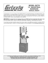
Figure 1. Control panel identification.
Control Panel Identification
A. Blade Height Key
B. Blade Tilt Key
C. Manual Increase Key
D. Manual Decrease Key
E. Scoring Blade Alignment Key
F. Scoring Blade Height Key
G. Number Keys
H. Input Confirmation Key
I. Millimeter/Inch Selection Key
J. Start Key
K. Stop Key
L. Decimal Key
M. Clear Key
N. Function Confirmation Key
O. Memory Set Key
P. Pre-Saved Memory Recall Key
Q. Cutting Width Key
R. Memory Set and Speed Display
S. Cutting Width Display
T. Blade Angle Display
U. Blade Height Display
C F G
H
I
J
K
M
O
P
Q
R
S
T
A
U
N
L
DB E
MAIN CONTROL PANEL
OPERATIONS

-4-
G0620 Main Control Panel
Quick Start
Manual Adjustments
The components controlled by the keys in Figure
2 can be manually adjusted using the and
keys.
Figure 2. Controls keys capable of manual
operation.
To manually adjust any of these components,
press one of the control keys shown in Figure
2
so its indicator light shines, then press
or as
desired to manually position the related control.
When finished, press the control key again so its
indicator light stops shining.
Note: You can press the Stop key at any time
to cancel the operation.
Only the blade height
, table tilt , and cutting
width controls allow numerical input. The scor-
ing blade height
and scoring blade alignment
controls must be adjusted by eye or by an
independent guide, such as a straightedge.
Typically manual controls are used when math
-
ematical adjustments are not practical, such as
those adjustments done by eye or when setting
the components to a marked workpiece.
Numerical Input Adjustments
The components controlled by the keys in Figure
3 can be controlled by numerical input and
will automatically adjust to the dimension you
entered. For more details on controlling any one
component, refer to the Section 3: Operations
.
Note: You can press the Stop key at any time
to cancel the operation.
Figure 3. Controls capable of being moved by
numerical input.
To move the components with numerical
input:
1. Press the desired control key ( , , and )
for the component that you want to move.
The indicator light on the key (Figure 3)
shines to tell you that the control panel is
ready to accept your input.
2. Enter your input with the number keypad.
As you press the keys, the display will flash
the numbers you have entered.
Example: If your input is 2.15", then you
would press the following keys:
.
3. Press the Start
key and the component will
move to where it is directed by your input.
Indicator Light

G0620 Main Control Panel
-5-
MM/Inch Selection
The control panel can display units in millimeters
or inches.
To toggle the display between mm and inches,
press and hold the mm/inch
key (Figure 4)
until the new unit of measure shows on the control
panel.
Note: The indicator light on the key shines next to
the unit of measure selected.
Figure 4. Pressing mm/inch key to toggle the
displayed unit of measure.
Press and
Hold
Figure 5 shows the keys used to adjust the scor-
ing blade, as discussed in this procedure.
You
can press the Stop key at any time to cancel
the operation.
Figure 5. Scoring blade controls keys.
Scoring Blade Height
1. Press the scoring blade height control
key.
The indicator light on the key shines to show
the selected control is active.
2. Use the plus and minus keys to posi-
tion the scoring blade. Typically, the scoring
blade is only adjusted about
1
⁄4"–
1
⁄2" above the
table.
3. When finished, press the Stop key, so the
indicator light stops shining.
Scoring Blade
Adjustments
Scoring Blade Alignment
1. Press the scoring blade alignment control
key.
The indicator light on the key shines to show
the selected control is active.
2. Use the plus and minus keys to align
the scoring blade with the main blade. (Use a
straightedge or the rip fence as a guide.)
3. When finished, press the Stop key, so the
indicator light stops shining.

-6-
G0620 Main Control Panel
Blade Height
Adjustments
The blade height can be adjusted manually or
numerically by entering in the desired blade
height. The adjustment can be cancelled at any
time by pressing the Stop
key.
Figure
6 shows the keys used during the blade
height adjustment procedures in this section.
Numerically Adjusting Blade Height
You can enter a desired blade height with the
number keys and the blade will automatically
adjust to that height.
To adjust the blade height automatically with
numerical input:
1. Press the blade height control
key.
The indicator light on the key shines to tell
you that the control panel is ready to accept
your input.
2. Enter your numerical input with the number
keys. As you press the keys, the display will
flash the numbers you have entered. If you
press a wrong number or make a mistake
with your input, press the clear
key and
start over.
Example: If you want the blade height to be
2.25", then you would press the following
keys: , and the display would look
similar to
Figure 7.
Note: It may be necessary to enter a zero
first if your numerical input is less than one.
Figure 7. Example of 2.25" entered into blade
height display.
3. Press the Start
key.
The control panel accepts your input, moves
the blade to your desired height, and the
indicator light on the blade height key stops
shining.
Manually Adjusting Blade Height
The blade height can be manually adjusted using
the plus
and minus keys. In some cases,
manual adjustments can save time by eliminating
measurements. For example, if you want to adjust
the blade height a little higher than the workpiece,
you can place the workpiece next to the blade and
use the manual controls to adjust the blade height
as desired.
To adjust the blade height manually:
1. Press the blade height control
key.
The indicator light on the key shines to show
that the control panel is ready for input.
2. Use the plus or minus key to manually
position the blade height. (Bump the keys for
small adjustments and hold the keys down for
large adjustments.)
3. When finished, press the Stop key, so the
indicator light stops shining.
Figure 6. Keys used in blade height adjustment
procedures.

G0620 Main Control Panel
-7-
Blade Tilt
Adjustments
The blade tilt can be adjusted manually or auto-
matically with numerical input. The adjustment
can be cancelled at any time by pressing the Stop
key.
Figure
8 shows the keys used during the blade tilt
adjustment procedures in this section.
Numerically Adjusting Blade Tilt
You can enter a desired angle with the number
keys and the blade will automatically adjust to that
angle.
To adjust the blade tilt automatically with
numerical input:
1. Press the blade tilt
key.
The indicator light on the key shines to tell
you that the control panel is ready to accept
your input.
2. Enter the desired blade tilt with the number
keys. As you press the keys, the display will
flash the numbers you have entered. If you
press a wrong number or make a mistake
with your input, press the clear
key and
start over.
Example: If you want the blade tilt to be
22.5", then you would press the following
keys:
, and the display would look
similar to
Figure 9.
Figure 9. Example of 22.5° entered into blade tilt
display.
3. Press the Start
key. The control panel
accepts your input, moves the blade to your
desired tilt, and the indicator light on the
blade tilt key stops shining.
Manually Adjusting Blade Tilt
The blade tilt can be manually adjusted using
the plus
and minus keys. In some cases,
manual adjustments can save time by eliminating
measurements. For example, if you want to adjust
the blade tilt to match an existing mitered cut, you
can place the workpiece next to the blade and
use the manual controls to adjust the blade tilt as
desired.
To adjust the blade tilt manually:
1. Press the blade tilt control
key. The indi-
cator light on the key shines to show that the
control panel is ready to accept input.
2. Use the plus or minus key to manu-
ally position the blade tilt. (Bump the keys for
small adjustments and hold the keys down for
large adjustments.)
3. When finished, press the Stop key, so the
indicator light stops shining.
Figure 8. Keys used in blade tilt adjustment
procedures.
NOTICE
Changes to the blade tilt affect blade height.
After performing Step 3, the blade height
will be different than shown in Figure
9. To
save time of having to re-enter the blade
height, enter the blade tilt before entering
blade height.

-8-
G0620 Main Control Panel
Rip Fence
Adjustments
The rip fence can be adjusted manually or auto-
matically with numerical input. The adjustment
can be cancelled at any time by pressing the Stop
key.
Figure
10 shows the keys used during the rip
fence adjustment procedures in this section.
Numerically Adjusting Rip fence
You can enter a desired cutting width with the
number keys and the rip fence will automatically
adjust to the specified distance away from the
blade.
To adjust the rip fence automatically with
numerical input:
1. Press the cutting width
key.
The indicator light on the key shines to tell
you that the control panel is ready to accept
your input.
2. Enter the desired cutting width with the num-
ber keys
.
As you press the keys, the display will flash
the numbers you have entered. If you press
a wrong number or make a mistake with your
input, press the clear
key and start over.
Example: If you want the cutting width to be
18.25", then you would press the following
keys:
, and the display would
look similar to
Figure 11.
Figure 11. Example of 18.25" entered into rip
fence cutting width display.
3. Press the Start
key. The control panel
accepts your input, moves the rip fence to the
desired distance away from the blade, and
the indicator light on the rip fence key stops
shining.
Manually Adjusting Rip fence
The rip fence can be manually adjusted using
the plus
and minus keys. In some cases,
manual adjustments can save time by eliminating
measurements. For example, if you have pen
-
ciled a cutline on a workpiece, you can place the
workpiece against the fence and use the manual
controls to align the cut line to the blade.
To adjust the rip fence manually:
1. Press the cutting width
key.
The indicator light on the key shines to show
that the control panel is ready to accept
input.
2. Use the plus or minus key to manually
position the rip fence. (Bump the keys for
small adjustments and hold the keys down for
large adjustments.)
3. When finished, press the Stop key, so the
indicator light stops shining.
Figure 10. Keys used in rip fence adjustment
procedures.
NOTICE
If the numerical input exceeds the compo-
nent limit, it will not completely move, and
may return an "OL" on the display.

G0620 Main Control Panel
-9-
Combining
Adjustment Entries
The controller has the ability to combine numeri-
cal input entries of the blade height, blade tilt, and
rip fence without closing the input cycle after each
entry. This is typically the most efficient way to set
up a new cut.
To enter multiple entries, follow the same steps
for numerical adjustments with each control, but
wait to press the Start
key until after the last
control input has been entered.
Example: If you want to set up a cut with a blade
height of 2.25", a blade tilt of 22.5°, and a cut
-
ting width of 18.25", you would do the following
steps:
1. Press the blade height
key.
The indicator light on the blade height
key
shines to show that the control panel is ready
to accept input.
2. Use the number keys to enter the blade
height (
Figure 12).
Figure 12. First entry.
Figure 13. Second entry.
Figure 14. Third entry.
3. Press the blade tilt
key.
The indicator light on the blade tilt
key
shines to show that the control panel is ready
to accept input.
The indicator light on the
blade height
key no longer shines, but the
numbers previously entered still flash.
5. Press the cutting width key.
The indicator light on the cutting width
key shines to show that the control panel is
ready to accept input. The indicator light on
the blade tilt
key no longer shines, but
both numbers previously entered continue to
flash.
6. Use the number keys to enter the cutting
width (Figure 14).
7. Press the Start
key.
All components will move to their respective
positions and the indicator light on the
cutting
width key will stop shining.
4. Use the number keys to enter in the blade
angle (
Figure 13).

-10-
G0620 Main Control Panel
Memory Functions
The Model G0620 controller can store up to 29
different cut settings. Each cut setting will save
positions for the blade height, blade angle, and rip
fence cutting width.
Saving Cut Settings
1. Move the blade height, blade angle, and rip
fence to the positions that you want to save.
(Refer to Combining Adjustment Entries
for more details on how to enter all these
dimensions at one time.)
For Example: Set the blade height to 2.25",
the blade angle 22.
5, and the rip fence posi-
tion 18.25", as shown in
Figure 15.
2. Press and hold the memory set key until
"S" displays in the blade speed display and
the other numbers flash, as shown in
Figure
16.
Figure 15. Example dimensions entered.
Figure 16. "S" displayed on control panel to
indicate system is ready to save settings.
3. Type in a number between 1 and 29 to repre-
sent this saved setting.
Figure 17. The number 22 programmed to save
the currently shown dimensions.
4. Press and hold the input confirmation key
until the display stops flashing. The screen
will return to the normal view, as shown in
Figure 18.
Figure 18. Screen returned to normal view.
Recalling Pre-Saved Settings
To demonstrate how saved settings are recalled,
move the components to the following positions
before beginning this procedure: blade height to
0.00, blade tilt to 0.0, rip fence position to 10.00.
(Refer to Combining Adjustment Entries for
more details on how to enter all these dimensions
at one time.)
To recall a saved setting:
1. Press and hold the pre-saved memory key
until "P" displays in the blade speed display
and the memory numbers flash, as shown in
Figure 19.
NOTICE
If the numerical input exceeds the compo-
nent limit, it will not completely move, and
may return an "OL" on the display.
Use the number 22 to save the example
dimensions from Step 1
. The display should
look like
Figure 17.

G0620 Main Control Panel
-11-
Figure 19. "P" displayed on control panel to
indicate system is ready to recall saved settings.
2. Type in the number of the saved setting you
want to recall, or use the plus
and minus
keys to scroll through each saved setting
to find the one you want.
Example: To recall the setting saved in the
example of the previous subsection,
press
the following keys:
. The display will
look similar to
Figure 20, showing the dimen-
sions of each of the three components.
Figure 20. Saved setting 22 entered into the
recall display.
4. Press and hold the input confirmation key
until the dimensions start flashing, as shown
in Figure 21.
Figure 21. Recalled dimensions flashing.
5. Press the Start
key.
All components will move to their respective
positions
Blade Diameter
Calibration
The exact dimensions of a blade can be pro-
grammed into the control panel, so the blade
height controls will not be skewed by blades of
different sizes. We recommend performing this
calibration procedure every time you change
blades, especially if changing between 12" and
14" blades.
Tools Needed Qty
Measuring Tape ................................................
1
To calibrate the control panel for your exact
blade diameter:
1. DISCONNECT SAW FROM POWER.
2. Remove blade, measure its diameter, then
reinstall it.
3. Connect saw to power, reset stop button, turn
ON the control panel, then turn it OFF.
4. Press and hold the blade height and cali-
brate keys at the same time, then turn the
control panel back
ON. After a few seconds,
the current blade diameter will flash and the
display will look similar to
Figure 22.
5. Press the clear key , then type in the exact
dimensions of your blade with the number
keys.
6. Press and hold the input confirmation key
until the display changes to the normal view.
Figure 22. Blade diameter display.

-12-
G0620 Main Control Panel
Blade Height
Calibration
Performing this procedure ensures that the blade
height displayed in the digital control panel is
accurate.
We recommend calibrating the blade height every
time the blade is changed.
The calibration is a simple procedure that only
takes minutes. For precise results, use a pair of
calipers to take the measurements noted below.
Note: You can stop the calibration process at any
time by pressing the Stop
key.
Tools Needed Qty
Calipers (Dial or Digital) ....................................
1
To calibrate the blade height:
1. DISCONNECT SAW FROM POWER!
2. Rotate the main blade so one of the carbide
teeth is at top dead center.
3. Measure the distance from the top of the
table to the top of the blade tooth, as shown
in Figure 23.
Figure 23. Measuring blade height with calipers.
5. Look at the current blade height displayed on
the control panel and compare that to your
measurement.
—If the blade height displayed is the same as
your measurement, then the blade height
calibration is already correct.
—If the displayed blade height is different
than what you measured, continue to the
next step to calibrate the blade height.
6. Press the blade height key.
The indicator light on the key shines to tell
you that the control panel is ready to accept
input for a new blade height.
7. Enter your measurement with the keypad.
As you press the keys, the display will flash
the numbers you have entered.
Example: If you measured 2.15", then you
would press the following keys:
,
and the display would look similar to
Figure
24.
Figure 24. Example of 2.15" entered into the
blade height display.
8. Press and hold the input confirmation key
until the display stops flashing.
The indicator light stops shining to tell you
that the control panel will no longer accept
input for the blade height.
4. Clear the calipers and any other objects
away from the blade, then connect the saw
to power.

G0620 Main Control Panel
-13-
Blade Tilt Calibration
Performing this procedure ensures that the blade
tilt displayed in the digital control panel is accu
-
rate.
The calibration is a simple procedure that only
takes minutes.
Note: You can stop the calibration process at any
time by pressing the Stop
key.
Tools Needed Qty
45° Square ........................................................
1
To calibrate the blade tilt:
1. Move the overhead blade guard out of the
way.
2. Raise the main blade as high as it will go.
3. Tilt the blade to 45°.
4. Place the 45° square flat on the table, push it
up against the blade (make sure it does not
contact a carbide tooth), and examine how
the square fits against the blade.
— If the square fits flat against the blade, then
the blade tilt calibration is already correct.
— If the square does not fit flat against the
blade (you can see a gap between the
square and the blade), then continue to the
next step to calibrate the blade tilt
.
5. Press the blade tilt
key. The indicator light
on the key shines to show that the control
panel is ready to accept input.
6. Use the plus or minus key to manually
position the blade tilt so it fits flat against the
45° square while the 45° is flat against the
table, as shown in
Figure 25.
7. Press the number
and keys to enter 45
degrees into the display.
8. Press and hold the input confirmation key
until the display stops flashing.
The indicator light stops shining to tell you
that the control panel will no longer accept
input for the blade height.
9. Return the blade position and blade guard
back to their original position.
Figure 25. 45° Square flat against table and
blade.

-14-
G0620 Main Control Panel
Rip Fence Cutting
Width Calibration
Performing this procedure ensures that cutting
width from the rip fence accurately matches what
is shown in the digital display.
We recommend calibrating the blade height every
time you change the blade.
The calibration is a simple procedure that only
takes minutes. For precise results, use a pair of
calipers to take the measurements noted below.
Note: You can stop the calibration process at any
time by pressing the Stop
key.
Tools Needed Qty
Calipers (Dial or Digital) ....................................
1
To calibrate the rip fence cutting width:
1. Raise the blade up to 2.25" high, tilt the blade
to 0.0, and move the rip fence 4" away from
the blade.
2. Measure the distance from the blade to the
fence by either making a test cut and measur
-
ing the result or by using a pair of calipers.
—If using a test cut to measure this dis
-
tance, make the test cut, measure your cut
workpiece, then proceed to Step 7
.
—If using calipers to make your measure
-
ment, proceed to Step 3
.
3. Completely close your calipers and make
sure they are at 0.000" (if not, zero them
now).
4. DISCONNECT SAW FROM POWER!
5. Close the calipers on one of the carbide teeth
on the main blade, then zero the calipers out.
(This will automatically subtract the blade
thickness when measuring the cutting width
in the next step.)
6. Place the bottom of the calipers on one of
the carbide teeth and extend the caliper mea
-
surement bar to touch the rip fence, as shown
in Figure 26, then lock the calipers in place
and read the measurement.
—If the measurement on the calipers reads
0.02" or less away from 4", then the rip
fence cutting width calibration is already
correct.
—If the measurement on the calipers reads
more than 0.02" away from 4", then the rip
fence cutting width must be recalibrated.
Continue to the next step.
Figure 26. Measuring cutting width with calipers.
7. Press the cutting width
key. The indicator
light on the key shines to show that the con
-
trol panel is ready to accept input.
8. Enter your measurement from Step 5 with
the keypad
.
As you press the keys, the display will flash
the numbers you have entered.
For Example: If you measured 4.15", then
you would press the following keys:
.
9. Press and hold the input confirmation key
until the display stops flashing. The new set
-
ting now remains on the display.

G0620 Main Control Panel
-15-
Rip Fence Thickness
Calibration
The rip fence can fit on the base in two positions,
as shown in
Figures 27 and 28. When the fence
is changed from one position to another, the con
-
trol panel automatically adjusts the dimensions
shown on the display so the cutting width remains
accurate. The control panel recognizes the fence
positions as A and B, as shown below.
Besides ensuring that the standard fence dimen
-
sions are calibrated correctly. The calibration
function can also be used if a sacrificial fence is
attached to the standard rip fence.
�
Figure 27. Fence position A.
�
Figure 28. Fence position B.
To calibrate the rip fence thickness:
1. Turn the control panel OFF.
2. Push and hold the blade width and CAL
keys, then turn ON the control panel. The
display will show A and B dimensions, as
shown in
Figure 29.
3. Press the clear key , then type in the exact
dimensions of your fence with the number
keys.
4. Type in a new dimension in the A line or
press the minus key to activate the B dimen
-
sion.
5. After entering the new dimension, press and
hold the input confirmation
.
The numbers you entered are now stored into
the control panel as the correct fence thick
-
ness.
Figure 29. Rip fence calibration mode.

-16-
G0620 Main Control Panel
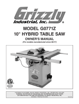
Figure 30. Control panel identification.
Control Panel Identification
PO
Q R
A
D
F GB
C E
H
I
L
M
N
J
K
A.
Low Battery Sign
B. *Angular Measuring Sign
C. *Angular Mode
D. *Increase Gap Sign
E. Absolute Mode
F. *Decrease Gap Sign
G. Function Key Activated Sign
H. *Current Relative Counter Number
I. Current Absolute Counter Number
(Memory Slots for Storing Offsets)
J. *Diameter Function
K. *Relative Measuring Mode
L. Millimeter Unit Display Mode
M. Inch Unit Display Mode
N. Numeric Display
O. Clear/Set Key
P. ABS/REL Key
Q. MM/Inch Key
R. Function/Enter Key
FENCE OPERATIONS
* Not applicable for this machine. Refer to the Foreword at the beginning of this manual for details.

G0620 Main Control Panel
-17-
MM/Inch Selection
The controller can display units in millimeters or
inches.
To toggle the display between mm and inches,
press the mm/inch
key (Figure 31) until the
new unit of measure shows on the control panel.
Figure 31. Pressing mm/inch key to toggle the
displayed unit of measure.
Press and
Release
Checking Battery
To check the remaining battery charge:
1. Press and hold the F/ENTER
key (the
sign will appear as this key is held down)
,
then press and release the mm/inch
key.
The controller displays the remaining charge
left in the battery, as shown in Figure 32
.
Figure 32. Current battery charge displayed.
The display will automatically exit out of the
battery charge screen after two seconds.
Changing Resolution
The display can be adjusted to show a resolu-
tion or accuracy from one to four decimal places,
depending on which unit of measure is selected.
To change the resolution:
1. Press and hold the F/ENTER
key (the
sign will appear as this key is held down)
,
then press and release the mm/inch
key.
The controller
displays the remaining power
left in the battery, as shown in Figure 32
.
2.
At the battery charge display screen, press
the CLR
/SET
key and the F/ENTER
key at the same time.
The controller displays the resolution, as
shown in Figure 33
.
Figure 33. Resolution displayed to two decimal
places.
3. Use the left and right arrows on the ABS/REL
and mm/inch
keys to select the desired
resolution.
4.
Press the F/ENTER
key to exit.

-18-
G0620 Main Control Panel
Calibrating the
Display
The controller can be calibrated to match the
actual measured distance from the blade to the
controller flip stop. This calibration is critical to
ensure that cutting results with the crosscut fence
are accurate.
To calibrate the controller:
1. Move the flip stop to the side of the fence that
would touch the workpiece, and measure the
distance between the flip stop and the blade.
2. Press the ABS/REL key, then release it to
make sure the controller is in the ABS mode.
3.
Press and hold the CLR/SET
key (the
sign will appear
), then press and release the
ABS/RE
L key, then release the CLR/SET
key.
The controller will display a small flashing "0",
which signals that it is ready to accept input
(see Figure 34).
5. Press the F/
ENTER
key to save the cur-
rent number in the controller as the "cali
-
brated" measurement. The controller is now
calibrated to be accurate from the flip stop to
the saw blade.
— If the calibrated distance is shown on the
display, no f
urther steps are necessary.
— If the calibrated number is not shown, con-
tinue to Step 6
.
6.
Press the ABS/REL key, then release it to
make sure the controller is in the ABS mode.
7. Press and hold the F/ENTER
key (the
sign will appear while
this key is held down),
then press and release the CLR
/SET
key,
then release the F/ENTER
key.
Figure 34. Display screen ready to accept
numerical input for calibration.
4. Use the left and right arrows on the ABS/REL
and mm/inch
keys to choose which dig-
its to modify
.
Modify the digits by pressing the CLR/SET
key when the chosen digit is blinking. When
you are done, the number on the controller
should match the measurement you took in
Step 1 (see Figure 35 for confirmation).
Figure 35. Numerical input of 8" entered for
calibration.
/