
COPYRIGHT © FEBRUARY, 2019 BY GRIZZLY INDUSTRIAL, INC.
WARNING: NO PORTION OF THIS MANUAL MAY BE REPRODUCED IN ANY SHAPE
OR FORM WITHOUT THE WRITTEN APPROVAL OF GRIZZLY INDUSTRIAL, INC.
#MN20291 PRINTED IN TAIWAN
The following change was recently made since the owner's manual was printed:
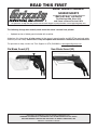
• Updated version of blade guard included with machine.
Aside from this information, all other content in the owner's manual applies and MUST be read and under-
stood for your own safety. IMPORTANT: Keep this update with the owner's manual for future reference.
For questions or help, contact our Tech Support at (570) 546-9663 or [email protected].
READ THIS FIRST
For questions or help with this product contact Tech Support at (570) 546-9663 or techsupport@grizzly.com
New Blade Guard (V3)
Old Blade Guard (V2)
Model G0605X1/G0606X1
G0696X/G0697X
***IMPORTANT UPDATE***
For Machines Mfd. Since 2/19
and Owner's Manual Revised 10/14

-2-
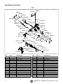
G0605X1-6X1, G0696X-97X Update (Mfd. 2/19+)
New Blade Guard Parts
200V3
200V3-1
200V3-2
200V3-3
200V3-4
200V3-5
200V3-6
200V3-7
200V3-8
200V3-9
200V3-10
200V3-11
200V3-13
200V3-14
200V3-15
200V3-16
200V3-17
200V3-20
200V3-33
200V3-3
200V3-4
200V3-5
200V3-7
200V3-3
200V3-7
200V3-6
200V3-8
200V3-3
200V3-7
200V3-8
200V3-5
200V3-31
200V3-32
200V3-12
200V3-21
200V3-22
200V3-23
200V3-24
200V3-25
200V3-26
200V3-27
200V3-28
200V3-29
200V3-30
A
200V3-21
A
200V3-1
200V3-18
200V3-19
200V3-18
200V3-6
REF PART # DESCRIPTION REF PART # DESCRIPTION
200V3 P0605X1200V3 BLADE GUARD ASSY V3.02.19 200V3-17 P0605X1200V3-17 MOUNTING BLOCK (RIGHT)
200V3-1 P0605X1200V3-1 FLAT HD SCR M4-.7 X 8 200V3-18 P0605X1200V3-18 PHLP HD SCR M4-.7 X 10
200V3-2 P0605X1200V3-2 UPPER COVER 200V3-19 P0605X1200V3-19 MOUNTING PIN
200V3-3 P0605X1200V3-3 HEX NUT M6-1 200V3-20 P0605X1200V3-20 ROLL PIN 5 X 40
200V3-4 P0605X1200V3-4 BLADE GUARD COVER 200V3-21 P0605X1200V3-21 FLAT WASHER 5MM
200V3-5 P0605X1200V3-5 FLAT WASHER 6MM 200V3-22 P0605X1200V3-22 ANTI-KICKBACK PAWL (LEFT)
200V3-6 P0605X1200V3-6 CONNECTING PLATE 200V3-23 P0605X1200V3-23 TORSION SPRING (LEFT)
200V3-7 P0605X1200V3-7 FLAT WASHER 6MM 200V3-24 P0605X1200V3-24 COMPRESSION SPRING
200V3-8 P0605X1200V3-8 FLAT HD SCR M6-1 X 16 200V3-25 P0605X1200V3-25 E-CLIP 7MM
200V3-9 P0605X1200V3-9 BRACKET 200V3-26 P0605X1200V3-26 TORSION SPRING (RIGHT)
200V3-10 P0605X1200V3-10 REAR COVER 200V3-27 P0605X1200V3-27 ANTI-KICKBACK PAWL (RIGHT)
200V3-11 P0605X1200V3-11 ROLL PIN 5 X 32 200V3-28 P0605X1200V3-28 PAWL MOUNTING BRACKET
200V3-12 P0605X1200V3-12 HEX NUT M5-.8 200V3-29 P0605X1200V3-29 PIN
200V3-13 P0605X1200V3-13 PHLP HD SCR M5-.8 X 6 200V3-30 P0605X1200V3-30 SHAFT
200V3-14 P0605X1200V3-14 KNOB BOLT 3-LOBE, M6-1 X 35 200V3-31 P0605X1200V3-31 SPREADER
200V3-15 P0605X1200V3-15 BLADE GUARD BODY 200V3-32 P0605X1200V3-32 PHLP HD SCR M5-.8 X 30
200V3-16 P0605X1200V3-16 MOUNTING BLOCK (LEFT) 200V3-33 P0605X1200V3-33 BLADE GUARD WARNING LABEL

COPYRIGHT © JULY, 2017 BY GRIZZLY INDUSTRIAL, INC.
WARNING: NO PORTION OF THIS MANUAL MAY BE REPRODUCED IN ANY SHAPE
OR FORM WITHOUT THE WRITTEN APPROVAL OF GRIZZLY INDUSTRIAL, INC.
#ES19101 PRINTED IN TAIWAN
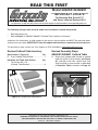
Revised Outfeed Table Inventory
The following changes were recently made since the owner's manual was printed:
• Revised inventory list.
• Revised Step 2 in G0605X1/G0606X1 Outfeed Table assembly instructions.
Aside from this information, all other content in the owner's manual applies and MUST be read and under-
stood for your own safety. IMPORTANT: Keep this update with the owner's manual for future reference.
For questions or help, contact our Tech Support at (570) 546-9663 or [email protected].
READ THIS FIRST
For questions or help with this product contact Tech Support at (570) 546-9663 or techsupport@grizzly.com
Model G0605X1/G0606X1
***IMPORTANT UPDATE***
For Machines Mfd. Since 07/17
and Owner's Manual Revised 10/14
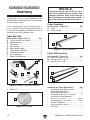
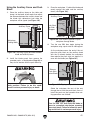
Box Contents: (Figure 15) Qty
F. Front Outfeed Table Bracket ...................... 1
Hardware and Tools (Not Shown): Qty
• Tap Screws M4 x 16
(Outfeed Table/Bracket) ............................. 8
Revised Assembly Steps
G0605X1/G0606X1 Outfeed Table
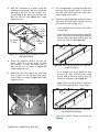
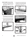
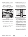
2. Attach front outfeed table bracket to outfeed
table with (8) M4 x 16 tap screws (see Figure
36), and then install feet, support legs, and
shelf end plate in same manner as described
in Extension Table instructions on Page 23.
Figure 15. Outfeed table components.
F
Figure 36. Outfeed table fastened to rear rail.
x8
Outfeed Table Bracket

COPYRIGHT © MARCH, 2017 BY GRIZZLY INDUSTRIAL, INC.
WARNING: NO PORTION OF THIS MANUAL MAY BE REPRODUCED IN ANY SHAPE
OR FORM WITHOUT THE WRITTEN APPROVAL OF GRIZZLY INDUSTRIAL, INC.
#JH18863 PRINTED IN TAIWAN
The following changes were recently made to this machine since the owner's manual was printed:
• Contactor manufacturer changed appearance/terminal numbers.
• Motor junction box wiring has changed.
Aside from this information, all other content in the owner's manual applies and MUST be read and under-
stood for your own safety. IMPORTANT: Keep this update with the owner's manual for future reference.
For questions or help, contact our Tech Support at (570) 546-9663 or [email protected].
READ THIS FIRST
For questions or help with this product contact Tech Support at (570) 546-9663 or techsupport@grizzly.com
***IMPORTANT UPDATE***
For Machines Mfd. Since July, 2016
and Owner's Manual Revised October 2014
Models G0605X1/G0606X1/
G0696X/G0697X
G0605X1/G0696X Magnetic Switch
OLD NEW
G0606X1/G0697X Magnetic Switch
OLD NEW
G0606X1/G0697X Magnetic Switch
OLD NEW
Changed Terminal Numbers
Changed Terminal Numbers

-2-
READ ELECTRICAL SAFETY
ON PAGE 77!
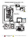
G0605X1-6X1, G0696X-97X Update (Mfd. 07/16)
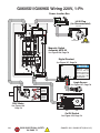
220V Motor
OFF
Magnetic Switch
Assembly MPE-30
Angle Sensor
Digital Readout
On/Off Switch
ON
AC2
R18
14 24
2313
AC1
L6-30 Plug
(As Recommended)
Run
Capacitor
35MFD
450VAC
Start
Capacitor
250MFD
300VAC
R/1/L1 T/5/L3 21S/3/L2
13
U/2/T1
W/6/T3
220V
V/4/T2
14
22
A
SDE
MA-30
Ground
Hot
Hot
220 VAC
G
X
Y
Ground
Power Junction Box
Installation work and
electrical wiring
must be done by
qualified electrician
in accordance with
all applicable codes
and standards.
RESET
96
98
1/2 3/4 5/6
18
22
26
OFF
95
SDE RA-30
B
G0605X1/G0696X Wiring 220V, 1-Ph

G0605X1-6X1, G0696X-97X Update (Mfd. 07/16)
-3-
READ ELECTRICAL SAFETY
ON PAGE 77!
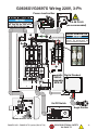
G0606X1/G0697X Wiring 220V, 3-Ph
R/1/L1 T/5/L3 NO13S/3/L2
NC21
U/2/T1
W/6/T3
220V
V/4/T2
NC22
NO14
95
A
SDE
MA-18
Ground
1/2 3/4 5/6
11
22
RESET
OFF
SDE RA-30
96 98
B
440V
Ground
Hot
Hot
Hot
L15-30 PLUG
(as recommended)
220 VAC
OFF ON
14 24
2313
Angle Sensor
Digital Readout
AC2
R18
AC1
On/Off Switch
Magnetic
Switch
Assembly
MPE-30
Motor@220V 3-Ph
If connecting machine to a phase
converter, the manufactured leg
must be connected to terminal L3.
PHASE CONVERTER
Power Junction Box
V2
U2
W2
W5
W1
V6
U6
W6
U5
V1
V5
U1
Ground
220V

-4-
READ ELECTRICAL SAFETY
ON PAGE 77!
G0605X1-6X1, G0696X-97X Update (Mfd. 07/16)
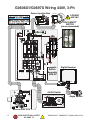
G0606X1/G0697X Wiring 440V, 3-Ph
R/1/L1 T/5/L3 NO13S/3/L2
NC21
U/2/T1
W/6/T3
220V
V/4/T2
NC22
NO14
A
SDE
MA-18
Ground
RESET
96
98
1/2 3/4 5/6
11
22
OFF
95
SDE RA-30
B
220V
OFF ON
14 24
2313
Angle Sensor
Digital Readout
AC2
R18
AC1
On/Off Switch
Magnetic
Switch
Assembly
MPE-30
Ground
Hot
Hot
Hot
DISCONNECT
SWITCH
(as recommended
)
3-PHASE
440 VAC
Motor@440V 3-Ph
Power Junction Box
440V
Ground
V2
U2
W2
V6
W1
V1
U6
U1
W6
V5
U5
W5

MODEL G0605X1/G0606X1/
G0696X/G0697X
12" LEFT TILTING TABLE SAW
OWNER'S MANUAL
COPYRIGHT © FEBRUARY, 2009 BY GRIZZLY INDUSTRIAL, INC. REVISED OCTOBER, 2014 (WK)
WARNING: NO PORTION OF THIS MANUAL MAY BE REPRODUCED IN ANY SHAPE
OR FORM WITHOUT THE WRITTEN APPROVAL OF GRIZZLY INDUSTRIAL, INC.
(FOR MODELS MANUFACTURED SINCE 8/11) #BL11524 PRINTED IN TAIWAN
Model G0697X
175370
Model G0606X1

This manual provides critical safety instructions on the proper setup,
operation, maintenance, and service of this machine/tool. Save this
document, refer to it often, and use it to instruct other operators.
Failure to read, understand and follow the instructions in this manual
may result in fire or serious personal injury—including amputation,
electrocution, or death.
The owner of this machine/tool is solely responsible for its safe use.
This responsibility includes but is not limited to proper installation in
a safe environment, personnel training and usage authorization,
proper inspection and maintenance, manual availability and compre-
hension, application of safety devices, cutting/sanding/grinding tool
integrity, and the usage of personal protective equipment.
The manufacturer will not be held liable for injury or property damage
from negligence, improper training, machine modifications or misuse.
Some dust created by power sanding, sawing, grinding, drilling, and
other construction activities contains chemicals known to the State
of California to cause cancer, birth defects or other reproductive
harm. Some examples of these chemicals are:
• Lead from lead-based paints.
• Crystalline silica from bricks, cement and other masonry products.
• Arsenic and chromium from chemically-treated lumber.
Your risk from these exposures varies, depending on how often you
do this type of work. To reduce your exposure to these chemicals:
Work in a well ventilated area, and work with approved safety equip-
ment, such as those dust masks that are specially designed to filter
out microscopic particles.

Table of Contents
INTRODUCTION ............................................... 2
Manual Accuracy ........................................... 2
Contact Info.................................................... 2
Machine Description ...................................... 2
Identification ................................................... 3
Machine Data Sheets .................................... 4
SECTION 1: SAFETY ....................................... 5
Safety Instructions for Machinery .................. 5
Additional Safety for Table Saws ................... 7
Preventing Kickback ...................................... 8
Protecting Yourself From Kickback................ 8
Glossary of Terms ......................................... 9
SECTION 2: POWER SUPPLY ...................... 10
Correcting Phase Polarity ........................... 12
Voltage Conversion...................................... 13
SECTION 3: SETUP ....................................... 14
Needed for Setup ......................................... 14
Unpacking .................................................... 14
Hardware Recognition Chart ....................... 15
G0605X1/G0606X1 Inventory ...................... 16
G0696X/G0697X Inventory .......................... 17
Cleanup ........................................................ 19
Site Considerations ...................................... 20
Assembly ..................................................... 21
Dust Collection ............................................. 26
Power Connection........................................ 27
Test Run ...................................................... 28
Final Setup ................................................... 29
Recommended Adjustments ........................ 29
SECTION 4: OPERATIONS ........................... 30
Basic Controls .............................................. 30
Operation Overview ..................................... 31
Disabling & Locking Switch.......................... 31
Non-Through & Through Cuts ..................... 32
Stock Inspection........................................... 32
Blade Requirements .................................... 33
Blade Selection ............................................ 33
Blade Installation.......................................... 34
Blade Guard Assembly ................................ 35
Riving Knife .................................................. 38
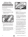
Cutting a Zero Clearance Insert .................. 39
Ripping ......................................................... 40
Crosscutting ................................................. 41
Miter Cuts..................................................... 41
Blade Tilt/Bevel Cuts ................................... 42
Dado Cutting ................................................ 42
Rabbet Cutting ............................................. 45
Resawing ..................................................... 47
SECTION 5: SHOP MADE SAFETY
ACCESSORIES .............................................. 50
Featherboards .............................................. 50
Push Sticks .................................................. 53
Push Blocks ................................................. 54
Narrow-Rip Auxiliary Fence & Push Block .. 55
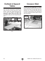
Outfeed & Support Tables ........................... 57
Crosscut Sled............................................... 57
SECTION 6: ACCESSORIES ......................... 58
SECTION 7: MAINTENANCE ......................... 60
Schedule ...................................................... 60
Cleaning ....................................................... 60
Unpainted Cast Iron ..................................... 60
Lubrication ................................................... 61
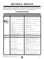
SECTION 8: SERVICE ................................... 62
Troubleshooting ........................................... 62
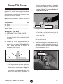
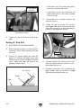
Blade Tilt Stops ............................................ 64
Miter Slot to Blade Parallelism ..................... 66
Blade Alignment ........................................... 67
Spreader or Riving Knife Alignment ............ 68
Fence Adjustments ...................................... 70
Fence Scale Calibration ............................... 72
Miter Gauge Adjustments ............................ 73
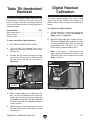
Table Tilt Handwheel Backlash ................... 74
Digital Readout Calibration .......................... 74
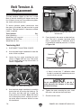
Belt Tension & Replacement ....................... 75
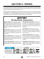
SECTION 9: WIRING ...................................... 77
Wiring Safety Instructions ............................ 77
Common Electrical Components ................. 78
G0605X1/G0696X Wiring 220V, 1-Ph ......... 79
G0606X1/G0697X Electrical Components .. 80
G0606X1/G0697X Wiring 220V, 3-Ph ......... 81
G0606X1/G0697X Wiring 440V, 3-Ph ......... 82
SECTION 10: PARTS ..................................... 83
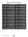
Motor and Arbor ........................................... 83
Cabinet ......................................................... 86
Blade Guard ................................................. 88
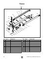
Fence ........................................................... 89
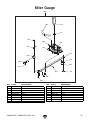
Miter Gauge ................................................. 90
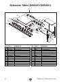
Extension Table (G0605X1/G0606X1) ........ 91
Rails (Model G0696X/G0697X) ................... 92
Outfeed Table (G0605X1/G0606X1) ........... 93
Labels & Cosmetic Parts ............................. 94
WARRANTY AND RETURNS ........................ 97

-2- G0605X1-6X1, G0696X-97X (Mfd. 8/11)
INTRODUCTION
Machine Description
This table saw features a steel cabinet-type stand
with a precision-ground cast iron table, plus
outfeed and extension tables for supporting wide
panels before, during and after a cut. Depending
upon the model, the motor is 5 or 7
1
⁄2 HP.
An internal dust port and sloped cabinet floor
directs saw dust into the 4" dust port, providing
highly effective dust removal. A poly-V serpentine
belt system efficiently transfers power.
Includes a digital blade-angle readout, T-style
fence, miter gauge, quick-release spreader/blade
guard, riving knife, and a zero-clearance table
insert.
We are proud to provide a high-quality owner’s
manual with your new machine!
We
made every effort to be exact with the
instruc-
tions, specifications, drawings, and photographs
contained inside. Sometimes we make mistakes,
but
our policy of continuous improvement
also
means that
sometimes the machine
you receive
will be slightly different than what is shown in
the manual
.
If you find this to be the case, and the difference
between the manual and machine leaves you
confused about a procedure
,
check our website
for an updated version. W
e post current
manuals
and
manual updates for free on our website at
www.grizzly.com
.
Alternatively, you can call our Technical Support
for help. Before calling, please write down the
Manufacture Date
and Serial Number
stamped
into the machine ID label (see below). This infor-
mation helps us determine if updated documenta-
tion is available for your machine.
Manufacture Date
Serial Number
Manual Accuracy
We stand behind our machines. If you have
any questions or need help, use the information
below to contact us. Before contacting, please get
the serial number and manufacture date of your
machine. This will help us help you faster.
Grizzly Technical Support
1203 Lycoming Mall Circle
Muncy, PA 17756
Phone: (570) 546-9663
Email: [email protected]
We want your feedback on this manual. What did
you like about it? Where could it be improved?
Please take a few minutes to give us feedback.
Grizzly Documentation Manager
P.O. Box 2069
Bellingham, WA 98227-2069
Email: [email protected]
Contact Info

G0605X1-6X1, G0696X-97X (Mfd. 8/11) -3-
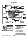
Figure 1. G0606X1 identification.
Identification
Front Rail
Tube
Fence
Fence
Scale
Indicator
Blade Tilt
Handwheel &
Lock
Blade Angle
Digital Readout
For Your Own Safety Read Instruction
Manual Before Operating Saw
a) Wear eye protection.
b) Use saw-blade guard and spreader for
every operation for which it can be used,
including all through sawing.
c) Keep hands out of the line of saw blade.
d) Use a push-stick when required.
e) Pay particular attention to instructions
on reducing risk of kickback.
f) Do not perform any operation freehand.
g) Never reach around or over saw blade.
To reduce the risk of
serious injury when using
this machine, read and
understand this entire
manual before beginning
any operations.
On/Off
Switch
Switch
Disabling Lock
Motor
Cover
Blade Height
Handwheel
Blade Height
Lock
Blade Tilt
Scale
Outfeed
Table
Miter
Gauge
Blade Guard &
Spreader
Front
Extension
Table
Front Rail
Fence Lock
Handle
Support
Leg

-4- G0605X1-6X1, G0696X-97X (Mfd. 8/11)
MODEL G0605X1/G0606X1/G0696X/G0697X
12" LEFT-TILTING TABLE SAWS
Model Number
G0605X1 G0606X1 G0696X G0697X
Motor
5 HP, 220V, 1-Ph 7
1
⁄2 HP, 220V/440V,
3-Ph
5 HP, 220V, 1-Ph 7
1
⁄2 HP, 220V/440V,
3-Ph
Required Power Supply Circuit
30 Amps 30 Amps @220V
15 Amps @440V
30 Amps 30 Amps @220V
15 Amps @440V
Speed
3450 RPM 3450 RPM 3450 RPM 3450 RPM
Power Requirement
220V, 1-Ph, 60 Hz 220V/440V, 3-Ph,
60 Hz
220V, 1-Ph, 60 Hz 220V/440V, 3-Ph,
60 Hz
Full Load Current Rating
18 19.5/10 18 19.5/10
Plug/Outlet Type (Recommended)
NEMA L6-30 L15-30/Hardwire NEMA L6-30 L15-30/Hardwire
Table Size (full assembly)
78
3
⁄4" x 30
3
⁄4" 78
3
⁄4" x 30
3
⁄4" 30
3
⁄4" x 48
3
⁄4" 30
3
⁄4" x 48
3
⁄4"
Table Height Above Floor
35
3
⁄4" 35
3
⁄4" 35
3
⁄4" 35
3
⁄4"
Overall Machine Size
91"L x 79
1
⁄4"W 91"L x 79
1
⁄4"W 75"L x 47"W 75"L x 47"W
Footprint Size
22
1
⁄2"L x 24"W 22
1
⁄2"L x 24"W 22
1
⁄2"L x 24"W 22
1
⁄2"L x 24"W
Weight
715 lbs. 715 lbs. 640 lbs. 640 lbs.
Fence Type
T-Shape T-Shape T-Shape T-Shape
Extension & Outfeed Tables
Yes Yes No No
Maximum Rip Right of Blade
52" 52" 36" 36"
Maximum Rip Left of Blade
18" 18" 18" 18"
Maximum Depth of Cut at 90°
4" 4" 4" 4"
Maximum Depth of Cut at 45°
2
3
⁄4" 2
3
⁄4" 2
3
⁄4" 2
3
⁄4"
Maximum Blade Diameter
12" 12" 12" 12"
Arbor Size
1" 1" 1" 1"
Arbor Speed
3600 RPM 3600 RPM 3600 RPM 3600 RPM
Rim Speed
11,310 FPM 11,310 FPM 11,310 FPM 11,310 FPM
Blade Tilt (Left)
0° – 45° 0° – 45° 0° – 45° 0° – 45°
Maximum Dado Width
3
⁄4"
3
⁄4"
3
⁄4"
3
⁄4"
Spreader/Riving Knife Thickness
0.09" (2.3mm) 0.09" (2.3mm) 0.09" (2.3mm) 0.09" (2.3mm)
Required Blade Body Thickness
0.074"–0.082"
(1.9–2.1mm)
0.074"–0.082"
(1.9–2.1mm)
0.074"–0.082"
(1.9–2.1mm)
0.074"–0.082"
(1.9–2.1mm)
Required Blade Kerf Thickness
0.114"– 0.122"
(2.9mm–3.1mm)
0.114"– 0.122"
(2.9mm–3.1mm)
0.114"– 0.122"
(2.9mm–3.1mm)
0.114"– 0.122"
(2.9mm–3.1mm)
Warranty
1 Year 1 Year 1 Year 1 Year

G0605X1-6X1, G0696X-97X (Mfd. 8/11) -5-
ELECTRICAL EQUIPMENT INJURY RISKS. You
can be shocked, burned, or killed by touching live
electrical components or improperly grounded
machinery. To reduce this risk, only allow qualified
service personnel to do electrical installation or
repair work, and always disconnect power before
accessing or exposing electrical equipment.
DISCONNECT POWER FIRST.
Always discon-
nect machine from power supply BEFORE making
adjustments, changing tooling, or servicing machine.
This prevents an injury risk from unintended startup
or contact with live electrical components.
EYE PROTECTION. Always wear ANSI-approved
safety glasses or a face shield when operating or
observing machinery to reduce the risk of eye
injury or blindness from flying particles. Everyday
eyeglasses are NOT approved safety glasses.
OWNER’S MANUAL. Read and understand this
owner’s manual BEFORE using machine.
TRAINED OPERATORS ONLY. Untrained oper-
ators have a higher risk of being hurt or killed.
Only allow trained/supervised people to use this
machine. When machine is not being used, dis-
connect power, remove switch keys, or lock-out
machine to prevent unauthorized use—especially
around children. Make workshop kid proof!
DANGEROUS ENVIRONMENTS. Do not use
machinery in areas that are wet, cluttered, or have
poor lighting. Operating machinery in these areas
greatly increases the risk of accidents and injury.
MENTAL ALERTNESS REQUIRED. Full mental
alertness is required for safe operation of machin-
ery. Never operate under the influence of drugs or
alcohol, when tired, or when distracted.
For Your Own Safety, Read Instruction
Manual Before Operating This Machine
The purpose of safety symbols is to attract your attention to possible hazardous conditions.
This manual uses a series of symbols and signal words intended to convey the level of impor-
tance of the safety messages. The progression of symbols is described below. Remember that
safety messages by themselves do not eliminate danger and are not a substitute for proper
accident prevention measures. Always use common sense and good judgment.
Indicates a potentially hazardous situation which, if not avoided,
MAY result in minor or moderate injury. It may also be used to alert
against unsafe practices.
Indicates a potentially hazardous situation which, if not avoided,
COULD result in death or serious injury.
Indicates an imminently hazardous situation which, if not avoided,
WILL result in death or serious injury.
This symbol is used to alert the user to useful information about
proper operation of the machine.
NOTICE
Safety Instructions for Machinery
SECTION 1: SAFETY

-6- G0605X1-6X1, G0696X-97X (Mfd. 8/11)
WEARING PROPER APPAREL. Do not wear
clothing, apparel or jewelry that can become
entangled in moving parts. Always tie back or
cover long hair. Wear non-slip footwear to avoid
accidental slips, which could cause loss of work-
piece control.
HAZARDOUS DUST. Dust created while using
machinery may cause cancer, birth defects, or
long-term respiratory damage. Be aware of dust
hazards associated with each workpiece material,
and always wear a NIOSH-approved respirator to
reduce your risk.
HEARING PROTECTION. Always wear hear-
ing protection when operating or observing loud
machinery. Extended exposure to this noise
without hearing protection can cause permanent
hearing loss.
REMOVE ADJUSTING TOOLS. Tools left on
machinery can become dangerous projectiles
upon startup. Never leave chuck keys, wrenches,
or any other tools on machine. Always verify
removal before starting!
USE CORRECT TOOL FOR THE JOB. Only use
this tool for its intended purpose—do not force
it or an attachment to do a job for which it was
not designed. Never make unapproved modifica-
tions—modifying tool or using it differently than
intended may result in malfunction or mechanical
failure that can lead to personal injury or death!
AWKWARD POSITIONS. Keep proper footing
and balance at all times when operating machine.
Do not overreach! Avoid awkward hand positions
that make workpiece control difficult or increase
the risk of accidental injury.
CHILDREN & BYSTANDERS. Keep children and
bystanders at a safe distance from the work area.
Stop using machine if they become a distraction.
GUARDS & COVERS. Guards and covers reduce
accidental contact with moving parts or flying
debris. Make sure they are properly installed,
undamaged, and working correctly.
FORCING MACHINERY. Do not force machine.
It will do the job safer and better at the rate for
which it was designed.
NEVER STAND ON MACHINE. Serious injury
may occur if machine is tipped or if the cutting
tool is unintentionally contacted.
STABLE MACHINE. Unexpected movement dur-
ing operation greatly increases risk of injury or
loss of control. Before starting, verify machine is
stable and mobile base (if used) is locked.
USE RECOMMENDED ACCESSORIES. Consult
this owner’s manual or the manufacturer for rec-
ommended accessories. Using improper acces-
sories will increase the risk of serious injury.
UNATTENDED OPERATION. To reduce the
risk of accidental injury, turn machine OFF and
ensure all moving parts completely stop before
walking away. Never leave machine running
while unattended.
MAINTAIN WITH CARE. Follow all maintenance
instructions and lubrication schedules to keep
machine in good working condition. A machine
that is improperly maintained could malfunction,
leading to serious personal injury or death.
CHECK DAMAGED PARTS. Regularly inspect
machine for any condition that may affect safe
operation. Immediately repair or replace damaged
or mis-adjusted parts before operating machine.
MAINTAIN POWER CORDS. When disconnect-
ing cord-connected machines from power, grab
and pull the plug—NOT the cord. Pulling the cord
may damage the wires inside. Do not handle
cord/plug with wet hands. Avoid cord damage by
keeping it away from heated surfaces, high traffic
areas, harsh chemicals, and wet/damp locations.
EXPERIENCING DIFFICULTIES. If at any time
you experience difficulties performing the intend-
ed operation, stop using the machine! Contact our
Technical Support at (570) 546-9663.

G0605X1-6X1, G0696X-97X (Mfd. 8/11) -7-
Additional Safety for Table Saws
HAND & BODY POSITIONING. Touching a spin-
ning saw blade will cause serious laceration or
amputation injuries. Keep hands away from saw
blade and out of blade path during operation, so
they cannot slip accidentally into blade. Stand to
side of blade path. Never reach around, behind, or
over blade. Only operate at front of machine; never
operate from rear or sides of saw.
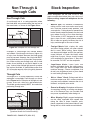
BLADE GUARD. Use blade guard for all “through
cuts” for which it can be used. (A through cut is an
operation where blade cuts completely through the
top of the workpiece.) Make sure the blade guard
is installed and adjusted correctly; promptly repair
or replace it if damaged. Always re-install blade
guard immediately after operations that require its
removal. Operating saw with blade guard removed
greatly increases risk of severe laceration or ampu-
tation injuries from accidental blade contact.
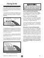
RIVING KNIFE. Use the riving knife for all “non-
through cuts” for which it can be used. (A non-
through cut is an operation where the blade does
not cut through the top of the workpiece.) Make
sure the riving knife is aligned and positioned cor-
rectly; and promptly repair or replace it if damaged.
Using the riving knife incorrectly will increase the
risk of kickback or accidental blade contact.
KICKBACK. Kickback occurs when the saw blade
ejects the workpiece back toward the operator.
Know how to reduce the risk of kickback, and learn
how to protect yourself if it does occur.
FEEDING WORKPIECE. Feeding workpiece
incorrectly will increase risk of kickback. Never
start saw with a workpiece touching blade; allow
blade to reach full speed before cutting. Only feed
workpiece against direction of blade rotation, from
front of saw. Never pull workpiece from behind
blade. Always use some type of guide (fence, miter
gauge, sliding table or sled, etc.) to feed workpiece
in a straight line. Never back a workpiece out of a
cut or move it backwards or sideways after starting
a cut. Feed cuts all the way through to completion.
Never perform any operation “freehand” (making
a cut without using a fence, miter gauge, or other
guide). Never plunge cut.
FENCE. Make sure the fence remains properly
adjusted and parallel with the blade. Always lock
the fence in place before using. Using or adjusting
the fence incorrectly will increase risk of kickback.
PUSH STICKS/BLOCKS. Use push sticks or push
blocks whenever possible to keep your hands far-
ther away from the blade while cutting; in the event
of an accident these devices will often take dam-
age that would have happened to hands/fingers.
CUT-OFF PIECES. Never use your hands to move
cut-offs away from the blade while the saw is run-
ning. If a cut-off becomes trapped between the
blade and table insert, turn the saw OFF and allow
the blade to completely stop before removing it.
BLADE ADJUSTMENTS. Adjusting the blade
height or tilt during operation increases the risk of
crashing the blade and sending metal fragments
flying with deadly force at the operator or bystand-
ers. Only adjust the blade height and tilt when the
blade is completely stopped and the saw is OFF.
CHANGING BLADES. Always disconnect power
before changing blades. Changing blades while
the saw is connected to power greatly increases
the injury risk if saw is accidentally powered up.
DAMAGED SAW BLADES. Never use blades
that have been dropped or otherwise damaged.
Damaged blades can fly apart and strike the oper-
ator with shards of metal.
DADO AND RABBET OPERATIONS. DO NOT
attempt dado or rabbeting operations without
first reading those sections in this manual. Dado
and rabbeting operations require special attention
because they must be performed with the blade
guard removed.
CUTTING CORRECT MATERIAL. Never cut
materials not intended for this saw; only cut natural
and man-made wood products, laminate covered
wood products, and some plastics. Cutting metal,
glass, stone, tile, etc. increases the risk of operator
injury due to kickback or flying particles.

-8- G0605X1-6X1, G0696X-97X (Mfd. 8/11)
Take the precautions below to avoid the most
common causes of kickback:
• Only cut workpieces with at least one smooth
and straight edge. DO NOT cut warped,
cupped or twisted wood.
• Never attempt freehand cuts. If the workpiece
is not fed parallel with the blade, kickback will
likely occur. Always use the rip fence or miter
gauge to support the workpiece.
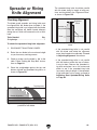
• Make sure the spreader or riving knife is
aligned with the blade. A misaligned spreader
or riving knife can cause the workpiece to
catch or bind, increasing the chance of kick-
back. If you think that your spreader or riving
knife is not aligned with the blade, check it
immediately!
• Take the time to check and adjust the rip
fence parallel with the blade; otherwise, the
chances of kickback are extreme.
• The spreader or riving knife maintains the
kerf in the workpiece, reducing the chance of
kickback. Always use the riving knife for all
non-through operations, unless a dado blade
is installed. Always use the spreader with the
blade guard for all through cuts.
• Feed cuts through to completion. Anytime
you stop feeding a workpiece in the middle
of a cut, the chance of kickback is greatly
increased.
• Keep the blade guard installed and in good
working order. Only remove it when per-
forming non-through cuts and immediately
re-install the blade guard when finished.
Remember, always use the riving knife for all
non-through operations, unless a dado blade
is installed.
• Make multiple, shallow passes when per-
forming a non-through cut. Making a deep
non-through cut will greatly increase the
chance of kickback.
Preventing Kickback
Statistics show that most common acci-
dents among table saw users can be
linked to kickback. Kickback is typically
defined as the high-speed expulsion of
stock from the table saw toward its opera-
tor. In addition to the danger of the opera-
tor or others in the area being struck by
the flying stock, it is often the case that
the operator’s hands are pulled into the
blade during the kickback.
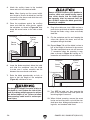
Even if you know how to prevent kickback, it
may still happen. Take these precautions to
protect yourself if kickback DOES occur:
• Stand to the side of the blade during every cut.
If kickback does occur, the thrown workpiece
usually travels directly in front of the blade.
• Wear safety glasses or a face shield. In the
event of kickback, your eyes and face are the
most vulnerable part of your body.
• Never, for any reason, place your hand
behind the blade. Should kickback occur,
your hand will be pulled into the blade.
• Use a push stick to keep your hands farther
away from the moving blade. If kickback
occurs, the push stick will most likely take
the damage that your hand would have
received.
• Use featherboards or anti-kickback devices
to prevent or slow down kickback.
Protecting Yourself
From Kickback
• Never move the workpiece backwards or try
to back it out of a cut while the blade is mov-
ing. If you cannot complete a cut for some
reason, stop the saw motor and allow the
blade to completely stop before backing the
workpiece out. Promptly fix the condition that
prevented you from completing the cut before
starting the saw again.

G0605X1-6X1, G0696X-97X (Mfd. 8/11) -9-
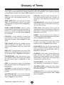
The following is a list of common definitions, terms and phrases used throughout this manual as they relate
to this table saw and woodworking in general. Become familiar with these terms for assembling, adjusting
or operating this machine. Your safety is VERY important to us at Grizzly!
ARBOR: A metal shaft extending from the drive
mechanism that is the mounting location for the
saw blade.
BEVEL EDGE CUT: A cut made with the blade
tilted to an angle between 0˚ and 45˚ to cut a bev-
eled edge onto a workpiece. Refer to Page 42 for
more details.
BLADE GUARD ASSEMBLY: Metal or plastic
safety device that mounts over the saw blade. Its
function is to prevent the operator from coming
into contact with the saw blade. Refer to Page 35
for more details.
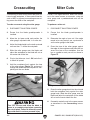
CROSSCUT: Cutting operation in which the
crosscut fence is used to cut across the shortest
width of the workpiece. Refer to Page 41 for more
details.
DADO BLADE: Blade or set of blades that are
used to cut grooves and rabbets. The saw and
arbor are not intended to safely use a larger dado
blade.
DADO CUT: Cutting operation that uses a dado
blade to cut a flat bottomed groove into the face of
the workpiece. Refer to Page 42 for more details.
FEATHERBOARD: Safety device used to keep
the workpiece against the rip fence and against
the table surface. Refer to Page 50 for more
details.
KERF: The resulting cut or gap in the workpiece
after the saw blade passes through during a cut-
ting operation.
KICKBACK: An event in which the workpiece is
propelled back towards the operator at a high rate
of speed.
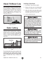
NON-THROUGH CUT: A cut in which the blade
does not cut through the top of the workpiece.
Refer to Page 32 for more details.
PARALLEL: Being an equal distance apart at
every point along two given lines or planes (i.e.
the rip fence face is parallel to the face of the saw
blade).
PERPENDICULAR: Lines or planes that intersect
and form right angles (i.e. the blade is perpendicu-
lar to the table surface).
PUSH STICK: Safety device used to push the
workpiece through a cutting operation. Used most
often when rip cutting thin workpieces. Refer to
Page 53 for more details.
RABBET: Cutting operation that creates an
L-shaped channel along the edge of the workpiece.
Refer to Page 45 for more details.
RIP CUT: Cutting operation in which the rip fence
is used to cut across the widest width of the
workpiece. Refer to Page 40 for more details.
RIVING KNIFE: Metal plate located behind the
blade. It maintains the kerf opening in the wood
when performing a cutting operation. Refer to
Page 38 for more details.
SPREADER: Metal plate located behind the
blade. Maintains kerf opening in wood when
performing a cutting operation. Acts as a barrier
behind blade to shield hands from being pulled
into the blade if kickback occurs.
STRAIGHTEDGE: A tool used to check the flat-
ness, parallelism, or consistency of a surface(s).
THIN KERF BLADE: A blade with a kerf or thick-
ness that is thinner than a standard blade cannot
be used on this saw.
THROUGH CUT: A cut in which the blade cuts
completely through the workpiece. Refer to Page
32 for more details.
Glossary of Terms

-10- G0605X1-6X1, G0696X-97X (Mfd. 8/11)
SECTION 2: POWER SUPPLY
Model G0606X1/G0697X
Circuit Requirements for 220V
This machine is prewired to operate on a power
supply circuit that has a verified ground and meets
the following requirements:
Nominal Voltage .............................. 220V/240V
Phase .................................................... 3-Phase
Circuit Rating ...................................... 30 Amps
Plug/Receptacle ......................... NEMA L15 -30
Cord .........4-Wire, 10 AWG, 300VAC, “S”-Type
Model G0605X1/G0696X
Circuit Requirements for 220V
This machine is prewired to operate on a power
supply circuit that has a verified ground and meets
the following requirements:
Nominal Voltage .............................. 220V/240V
Phase .................................................... 1-Phase
Circuit Rating ...................................... 30 Amps
Plug/Receptacle ...........................NEMA L6-30
Cord .........3-Wire, 12 AWG, 300VAC, “S”-Type
G0605X1/G0696X
Full-Load Current at 220V ................. 18 Amps
G0606X1/G0697X
Full-Load Current at 220V .............. 19.5 Amps
Full-Load Current at 440V ................. 10 Amps
Circuit InformationAvailability
Before installing the machine, consider the avail-
ability and proximity of the required power supply
circuit. If an existing circuit does not meet the
requirements for this machine, a new circuit must
be installed. To minimize the risk of electrocution,
fire, or equipment damage, installation work and
electrical wiring must be done by an electrician or
qualified service personnel in accordance with all
applicable codes and standards.
Electrocution, fire, or
equipment damage may
occur if machine is not
correctly grounded and
connected to the power
supply.
Full-Load Current Rating
The full-load current rating is the amperage a
machine draws at 100% of the rated output power.
On machines with multiple motors, this is the
amperage drawn by the largest motor or sum of all
motors and electrical devices that might operate
at one time during normal operations.
The full-load current is not the maximum amount
of amps that the machine will draw. If the machine
is overloaded, it will draw additional amps beyond
the full-load rating.
If the machine is overloaded for a sufficient length
of time, damage, overheating, or fire may result—
especially if connected to an undersized circuit.
To reduce the risk of these hazards, avoid over-
loading the machine during operation and make
sure it is connected to a power supply circuit that
meets the specified circuit requirements.
For your own safety and protection of
property, consult an electrician if you are
unsure about wiring practices or electrical
codes in your area.
Note: Circuit requirements in this manual apply to
a dedicated circuit—where only one machine will
be running on the circuit at a time. If machine will
be connected to a shared circuit where multiple
machines may be running at the same time, con-
sult an electrician or qualified service personnel to
ensure circuit is properly sized for safe operation.
A power supply circuit includes all electrical
equipment between the breaker box or fuse panel
in the building and the machine. The power sup-
ply circuit used for this machine must be sized to
safely handle the full-load current drawn from the
machine for an extended period of time. (If this
machine is connected to a circuit protected by
fuses, use a time delay fuse marked D.)

G0605X1-6X1, G0696X-97X (Mfd. 8/11) -11-
Model G0606X1/G0697X
Circuit Requirements for 440V
This machine can be converted to operate on a
power supply circuit that has a verified ground
and meets the requirements listed below. (Refer
to Voltage Conversion instructions for details.)
Nominal Voltage .............................. 440V/480V
Cycle ..........................................................60 Hz
Phase .................................................... 3-Phase
Circuit Rating ...................................... 15 Amps
Connection ......Hardwire with Locking Switch
Model G0606X1/G0697X
Connection Device
For 220V operation: The power cord and plug
specified under “
Circuit Requirements for 220V”
on the previous page have an equipment-ground-
ing wire and a grounding prong. The plug must
only be inserted into a matching receptacle
(outlet) that is properly installed and grounded in
accordance with all local codes and ordinances
(see figure below).
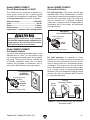
Figure 4. Typical hardwire setup with a locking
disconnect switch.
Power
Source
Locking
Disconnect Switch
Machine
Ground
Ground
ConduitConduit
Figure 3. Typical L15-30 plug and receptacle.
Grounding Prong
is Hooked
Current Carrying Prongs
GROUNDED
L15-30 RECEPTACLE
L15-30
PLUG
Serious injury could occur if you connect
the machine to power before completing the
setup process. DO NOT connect to power
until instructed later in this manual.
Model G0605X1/G0696X
Connection Device
The power cord and plug specified under “Circuit
Requirements for 220V”
on the previous page
has an equipment-grounding wire and a ground-
ing prong. The plug must only be inserted into
a matching receptacle (outlet) that is properly
installed and grounded in accordance with all
local codes and ordinances (see figure below).
Figure 2. Typical L6-30 plug and receptacle.
Grounding Prong
is Hooked
Current Carrying Prongs
L6-30 GROUNDED
LOCKING
RECEPTACLE
L6-30
LOCKING
PLUG
For 440V operation: As specified in “Circuit
Requirements for 440V” on the previous page, the
machine must be hardwired to the power source,
using a locking switch as a disconnecting means
(see below). The machine must also be connect-
ed to a grounded metal permanent wiring system;
or to a system having an equipment-grounding
conductor. Due to the complexity and high voltage
involved, this type of installation MUST be done
by a qualified electrician.
Page is loading ...
Page is loading ...
Page is loading ...
Page is loading ...
Page is loading ...
Page is loading ...
Page is loading ...
Page is loading ...
Page is loading ...
Page is loading ...
Page is loading ...
Page is loading ...
Page is loading ...
Page is loading ...
Page is loading ...
Page is loading ...
Page is loading ...
Page is loading ...
Page is loading ...
Page is loading ...
Page is loading ...
Page is loading ...
Page is loading ...
Page is loading ...
Page is loading ...
Page is loading ...
Page is loading ...
Page is loading ...
Page is loading ...
Page is loading ...
Page is loading ...
Page is loading ...
Page is loading ...
Page is loading ...
Page is loading ...
Page is loading ...
Page is loading ...
Page is loading ...
Page is loading ...
Page is loading ...
Page is loading ...
Page is loading ...
Page is loading ...
Page is loading ...
Page is loading ...
Page is loading ...
Page is loading ...
Page is loading ...
Page is loading ...
Page is loading ...
Page is loading ...
Page is loading ...
Page is loading ...
Page is loading ...
Page is loading ...
Page is loading ...
Page is loading ...
Page is loading ...
Page is loading ...
Page is loading ...
Page is loading ...
Page is loading ...
Page is loading ...
Page is loading ...
Page is loading ...
Page is loading ...
Page is loading ...
Page is loading ...
Page is loading ...
Page is loading ...
Page is loading ...
Page is loading ...
Page is loading ...
Page is loading ...
Page is loading ...
Page is loading ...
Page is loading ...
Page is loading ...
Page is loading ...
Page is loading ...
Page is loading ...
Page is loading ...
Page is loading ...
Page is loading ...
Page is loading ...
Page is loading ...
Page is loading ...
Page is loading ...
-
 1
1
-
 2
2
-
 3
3
-
 4
4
-
 5
5
-
 6
6
-
 7
7
-
 8
8
-
 9
9
-
 10
10
-
 11
11
-
 12
12
-
 13
13
-
 14
14
-
 15
15
-
 16
16
-
 17
17
-
 18
18
-
 19
19
-
 20
20
-
 21
21
-
 22
22
-
 23
23
-
 24
24
-
 25
25
-
 26
26
-
 27
27
-
 28
28
-
 29
29
-
 30
30
-
 31
31
-
 32
32
-
 33
33
-
 34
34
-
 35
35
-
 36
36
-
 37
37
-
 38
38
-
 39
39
-
 40
40
-
 41
41
-
 42
42
-
 43
43
-
 44
44
-
 45
45
-
 46
46
-
 47
47
-
 48
48
-
 49
49
-
 50
50
-
 51
51
-
 52
52
-
 53
53
-
 54
54
-
 55
55
-
 56
56
-
 57
57
-
 58
58
-
 59
59
-
 60
60
-
 61
61
-
 62
62
-
 63
63
-
 64
64
-
 65
65
-
 66
66
-
 67
67
-
 68
68
-
 69
69
-
 70
70
-
 71
71
-
 72
72
-
 73
73
-
 74
74
-
 75
75
-
 76
76
-
 77
77
-
 78
78
-
 79
79
-
 80
80
-
 81
81
-
 82
82
-
 83
83
-
 84
84
-
 85
85
-
 86
86
-
 87
87
-
 88
88
-
 89
89
-
 90
90
-
 91
91
-
 92
92
-
 93
93
-
 94
94
-
 95
95
-
 96
96
-
 97
97
-
 98
98
-
 99
99
-
 100
100
-
 101
101
-
 102
102
-
 103
103
-
 104
104
-
 105
105
-
 106
106
-
 107
107
-
 108
108


Ask a question and I''ll find the answer in the document
Finding information in a document is now easier with AI
Related papers
-
 Grizzly Industrial G0696X User manual
-
 Grizzly Industrial G0771Z User manual
-
Grizzly Industrial G0826 Owner's manual
-
 Grizzly Industrial G0528 Owner's manual
-
 Grizzly Industrial G0651 Owner's manual
-
 Grizzly Industrial G0652 Owner's manual
-
 Grizzly Industrial G0636X User manual
-
 Grizzly Industrial G0690 Owner's manual
-
 Grizzly Industrial G0690 Owner's manual
-
 Grizzly Industrial G4181 Owner's manual


