Page is loading ...

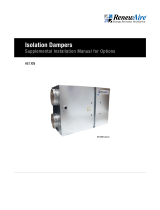
FACTORY-INSTALLED YASKAWA VARIABLE
FREQUENCY DRIVES IN RENEWAIRE UNITS
Supplemental Manual for Options
FOR COMMERCIAL UNITS
YASKAWA V1000 SHOWN
VFD KEYPADS IN E-BOX

1.800.627.4499
Yaskawa Variable Frequency DrivesOPTION
2
WARNING
RISK OF FIRE, ELECTRIC SHOCK, OR INJURY.
OBSERVE ALL CODES AND THE FOLLOWING:
1. Before servicing or cleaning the unit, switch power off at
disconnect switch or service panel and lock-out/tag-out to
prevent power from being switched on accidentally. More
than one disconnect switch may be required to de-energize
the equipment for servicing.
2. This installation manual shows the suggested installation
method. Additional measures may be required by local
codes and standards.
3. Installation work and electrical wiring must be done by qual-
ified professional(s) in accordance with all applicable codes,
standards and licensing requirements.
4. Any structural alterations necessary for installation must
comply with all applicable building, health, and safety code
requirements.
5. This unit must be grounded.
6. Use the unit only in the manner intended by the manufactur-
er. If you have questions, contact the manufacturer.
7. When cutting or drilling into unit, wall or ceiling, do not dam-
age electrical wiring and other hidden utilities.
8. Do not re-wire the Variable Frequency Drive(s) (VFD) to
control more than one motor per VFD.
9. Do not operate the motors in this unit above the motor’s rat-
ed full load amps (FLA) as indicated on the unit’s nameplate.
Follow all local codes.
CAUTION
DO NOT OPERATE VFD IN CONDITIONS OUTSIDE OF TEMPERA-
TURE LIMITS. The manufacturer’s published ambient tempera-
ture limits for V1000 VFDs are 14°F to 122°F. RenewAire has
performed extensive ambient temperature validation tests that
demonstrates the VFDs may be operated at a lower tempera-
ture limit for starting the VFD down to -22°F. It is recom-
mended that the VFD not be operated for prolonged periods
at temperatures below 14°F to ensure longevity of the VFD.
As RenewAire commercial ERVs are VFD ready, consider field
installing VFDs in a climate controlled indoor electrical cabinet
when ERV is installed in extreme climates.
WARNING
Capacitors in VFDs Retain Charge
Allow 3 minutes after shutting off power to the VFDs to allow
the capacitors in the VFD to fully discharge. Do not connect or
disconnect wires at the VFD without waiting 3 minutes.
WARNING
DANGER OF MOTOR OVERLOAD LEADING TO SMOKE
AND FIRE!
Do not change parameters L3-02 and L3-06 from RenewAire
default settings, which should be set to no more than 125% of
the ratio of Motor FLA / VFD FLA. These parameters set the
limits of output current provided by the VFD.

31.800.627.4499
Yaskawa Variable Frequency Drives OPTION
1.0 OVERVIEW 4
1.1 ABOUT YASKAWA VARIABLE FREQUENCY
DRIVES (VFDS) .......................................................4
1.2 PLANNING YOUR INSTALLATION ..............................4
1.2.1 “ON” and “SPEED” Signals ................................................ 5
1.2.2 Principles of External Control ............................................. 5
1.2.3 Connecting External Controls ............................................. 5
1.2.4 Wire Routing ...................................................................... 5
1.2.5 Purpose of Providing Keypad .............................................. 6
2.0 INSTALLATION 7
2.1 WIRING OPTIONS ....................................................7
2.1.1 “ON” Signal Connections .................................................... 7
2.2 WIRING SCHEMATICS..............................................7
2.2.1 Analog Inputs to Provide the “SPEED” Signal ...................... 9
2.2.2 Wiring Two VFDs for Leader-Follower Operation ................. 9
2.2.3 Using VFD Presets for the “SPEED” Signals .......................10
2.2.4 Use with a CO2 Controller .................................................11
3.0 OPERATION 12
3.1 INITIAL START-UP .................................................12
3.1.1 To Start ERV ...................................................................... 12
3.1.2 Motor Protection by the VFD(s) ..........................................12
3.2 SETTINGS .............................................................13
3.2.1 VFD Parameter Overview ..................................................13
3.2.2 To View All VFD Parameters ..............................................13
3.2.3 To Change VFD Parameters ...............................................13
3.2.4 To Change VFD Parameters (when parameters
are unlocked) ...................................................................14
3.2.5 To View Only Changed VFD Parameters .............................14
3.2.6 Summary Table of Commonly Used Parameters .................15
3.2.7 To Reset VFD Parameters to Factory Settings
using Keypad .................................................................... 17
3.2.8 Scaling and Response to Analog Inputs .............................18
3.2.9 Additional Job Information Needed ....................................18
3.2.10 Application Example: CO2 Controller ................................ 18
3.2.11 Example of VFD Scaling .................................................. 21
4.0 FACTORY ASSISTANCE 22
TABLE OF CONTENTS
TABLE OF ILLUSTRATIONS
Figure 1.2.0 Yaskawa Keypad Buttons ..........................................6
Figure 2.2.0 Connection of “ON” Signals to Low-Voltage Terminal
Strip in ERV E-box .................................................... 7
Figure 2.2.1 Factory Control Wiring: “ON” Signals Connected to
Each VFD .................................................................8
Figure 2.2.2 Alternate Control Wiring ...........................................8
Figure 2.2.3 Examples of Analog Input Connections .....................9
Figure 2.2.4 Leader-Follower Connection .....................................9
Figure 2.2.5 Use of 3 Switches to Command the VFD to Operate at
Any of 3 Pre-set Speeds
(SP4T Switch Alternatively)..................................... 10
Figure 2.2.6 Example of Operation of 2 VFDs by a
CO2 Controller ....................................................... 11

1.800.627.4499
Yaskawa Variable Frequency DrivesOPTION
4
OVERVIEW
1.0 OVERVIEW
1.1 ABOUT YASKAWA VARIABLE FREQUENCY DRIVES (VFDS)
This manual supplements RenewAire’s standard Installation and Operation Manuals, which do
not include information on units equipped with Yaskawa VFDs. RenewAire uses Yaskawa VFDs
for some models, typically those using a 208-230VAC or 460VAC power supply.
Yaskawa V1000 VFDs are supplied in both indoor and outdoor Energy Recovery Units (ERVs) and
have the ability to include a BACnet building communication protocol interface.
For complete ERV installation you will also need:
u Standard Installation and Operation Manual for the ERV—physical installation and duct
connection, maintenance procedures, etc.
u Supplemental Wiring Schematic Manual—complete unit wiring diagrams.
u User's Manual V1000—Yaskawa's Manuals–User Guides.
More detailed information is available online in the Downloads page at https://www.yaskawa.
com/downloads.
NOTE: VFD(s) in this
unit can be operated
in many ways. This
Manual provides
only an outline of
common methods.
WARNING
RISK OF FIRE, ELECTRIC SHOCK, OR INJURY.
OBSERVE ALL CODES AND THE FOLLOWING:
1. Before servicing or cleaning the unit, switch power off at disconnect switch or service
panel and lock-out/tag-out to prevent power from being switched on accidentally. More
than one disconnect switch may be required to de-energize the equipment for servicing.
2. This installation manual shows the suggested installation method. Additional measures
may be required by local codes and standards.
3. Installation work and electrical wiring must be done by qualified professional(s) in accor-
dance with all applicable codes, standards and licensing requirements.
4. Any structural alterations necessary for installation must comply with all applicable build-
ing, health, and safety code requirements.
5. This unit must be grounded.
6. Use the unit only in the manner intended by the manufacturer. If you have questions,
contact the manufacturer.
7. When cutting or drilling into unit, wall or ceiling, do not damage electrical wiring and other
hidden utilities.
8. Do not re-wire the VFD(s) to control more than one motor per VFD.
9. Do not operate the motors in this unit above the motor’s rated full load amps (FLA) as
indicated on the unit’s nameplate. Follow all local codes.
1.2 PLANNING YOUR INSTALLATION
CAUTION
DO NOT OPERATE VFD IN CONDITIONS OUTSIDE OF TEMPERATURE LIMITS. The manufactur-
er’s published ambient temperature limits for V1000 VFDs are 14°F to 122°F. RenewAire has
performed extensive ambient temperature validation tests that demonstrates the VFDs may
be operated at a lower temperature limit for starting the VFD down to -22°F. It is recom-
mended that the VFD not be operated for prolonged periods at temperatures below 14°F to
ensure longevity of the VFD. As RenewAire commercial ERVs are VFD ready, consider field
installing VFDs in a climate controlled indoor electrical cabinet when ERV is installed in
extreme climates.

51.800.627.4499
Yaskawa Variable Frequency Drives OPTION
OVERVIEW
1.2.1 “ON” and “SPEED” Signals
VFD operation in this unit is dependent on two signals: an “ON” signal and a “SPEED” (or
REFERENCE) signal. The sources and types of these signals can vary. If the ERV is equipped
with dampers, the “ON” signal to the VFD comes from the end switch on the damper. If the
ERV is not equipped with dampers, the “ON” signal comes from an external control connected
directly to the VFD. When an “ON” signal is received by the VFD, it starts the motor. The VFD
then operates the blower at the speed established by the “SPEED” signal. The “SPEED” signal
is often provided by an external control, but in some applications “pre-set” speeds are set
inside the VFD and are selected by external switches or relays.
1.2.2 Principles of External Control
This ERV can be operated by various external control devices including remote switch or relay,
digital time clock with relay, occupancy sensor with relay, and carbon dioxide sensor with relay
and analog output. These devices are commonly known as 2-wire, 3-wire, and 4-wire devices.
A Building Management System (BMS) can control this ERV through relay contacts and with
0–10vdc or 4–20mA analog inputs.
The external control devices can be connected to this ERV to operate each blower independently
or in a leader-follower configuration. In leader-follower mode, a single external switch or relay
calls for operation and the leader VFD sets “SPEED” to internal presets, or in response to an
analog input signal. The follower VFD then operates at either exactly the same speed, at an
offset above or below the leader’s speed, or at a scaled speed.
The VFD’s are pre-programmed at the factory so only a few parameters need change for a
specific installation.
1.2.3 Connecting External Controls
If this ERV is equipped with damper(s), the “ON” signal is connected to the terminal strip in
the electrical enclosure (e-box). If this ERV is not equipped with damper(s), and has 2 VFDs,
the “ON” signal is connected directly to the VFDs. The “SPEED” signals are always connected
directly to the VFD(s).
1.2.4 Wire Routing
Route input power cables, motor cables and control cables separately to decrease
electromagnetic interference caused by the rapid changes in the drive output voltage. Where
control cables must cross power cables make sure that they are arranged at an angle as near to
90 degrees as possible.
Power cables and control cables can be brought into the bottom of the e-box attached to the
ERV unit or through the bottom of the unit itself. There are plugged holes to run control wires
and power wires between the electrical box and the unit interior, marked on the interior of the
ERV unit and another plugged hole in the unit compartment divider to run wires to VFDs in the
other airstream compartment if needed.
In some configurations the VFD and/or VFD protective guard may need to be removed to
access the control wire hole plug to run wires. A label is located in the ERV on the left interior
wall indicating the power and control wire hole plug locations. Bring wires out from the top
or bottom of the VFD mounting bracket and not through the mounting bracket window when
routing wires if the VFD is mounted over the hole plug.
After the wires are run, apply caulk around the wires at wire bushings used between the
electrical box and ERV unit and between compartments in the unit to prevent air leakage
between these compartments.

1.800.627.4499
Yaskawa Variable Frequency DrivesOPTION
6
OVERVIEW
1.2.5 Purpose of Providing Keypad
Each VFD has a keypad which is accessible at the e-box while the unit is operating.
Parameter adjustments, VFD operation status, and manual control of the VFD are all functions
of the keypad.
VFD is factory programmed to cover most needs but some parameters will need to be set to
interact with the external control system.
Access the keypad(s) through the removable cover to the e-box.
FIGURE 1.2.0 YASKAWA KEYPAD BUTTONS
UP/DOWN
LOCAL/REMOTE
ENTER
STOPRUN
RESET/
ARROW RIGHT
ESCAPE

71.800.627.4499
Yaskawa Variable Frequency Drives OPTION
INSTALLATION
2.0 INSTALLATION
2.1.1 “ON” Signal Connections
Depending on features installed, connect ON-SIGNAL connections either to the VFDs
themselves, or to the low-voltage terminal strip in the ERV e-box. See schematics below.
Install a jumper between terminals 2 and 3 to use the ERV’s on-board 24VAC power. Do this
when the external control(s) have isolated contacts that don’t provide any voltage, as in the
top two examples. Make no connections between terminals 1 and 2 and terminals 3–5 if the
external control has a voltage output to provide the “ON” signal. This voltage must be 24VAC.
WARNING
Capacitors in VFDs Retain Charge
Allow 3 minutes after shutting off power to the VFDs to allow the capacitors in the VFD to fully
discharge. Do not connect or disconnect wires at the VFD without waiting 3 minutes.
FIGURE 2.2.0 CONNECTION OF “ON” SIGNALS TO LOW-VOLTAGE TERMINAL STRIP IN ERV E-BOX
2.2 WIRING SCHEMATICS
2.1 WIRING OPTIONS

1.800.627.4499
Yaskawa Variable Frequency DrivesOPTION
8
NOTE: ERV may
optionally have only
one VFD.
See Figure 2.2.0 for Relay or Damper Actuator Connection alternatives.
FIGURE 2.2.2 ALTERNATE CONTROL WIRING
FIGURE 2.2.1 FACTORY CONTROL WIRING: “ON” SIGNALS CONNECTED TO EACH VFD
Alternative Control Wiring: “ON” signal connected directly to one VFD, passed to second VFD
from terminals MA and MC.
INSTALLATION

91.800.627.4499
Yaskawa Variable Frequency Drives OPTION
2.2.1 Analog Inputs to Provide the “SPEED” Signal
Analog inputs are connected as shown below. It may be necessary to scale the response of the
VFD to the analog “SPEED” signal.
NOTE: All wiring
for analog signals
connected to the
VFDs should be
double- or single-shielded
twisted-pair cable. Ground
the shield at one end of the
cable only. The grounding
clamp on the VFD may
be used.
FIGURE 2.2.3 EXAMPLES OF ANALOG INPUT CONNECTIONS
2.2.2 Wiring Two VFDs for Leader-Follower Operation
One VFD can provide the “SPEED” signal to a second VFD, as shown below.
NOTE: If the FA
VFD is controlled
by an analog input
signal, it is likely
that the FA VFD’s response
to the analog input will be
scaled, using parameters
H3-03 and H3-04 for the
A1 input, or H3-11 and
H3-12 for the A2 input. See
example VFD Parameter
Scaling in section 3.3.8.
Parameter H4-02 and H4-
03 can be used to scale
the Analog Output of the
Leader VFD in order to
offset or correct the speed
of the “Follower” VFD.
If both VFDs are to run at
the same speed, no scaling
parameters need be ap-
plied to the EA VFD since it
is controlled as
a “Follower.”
FIGURE 2.2.4 LEADER-FOLLOWER CONNECTION
INSTALLATION

1.800.627.4499
Yaskawa Variable Frequency DrivesOPTION
10
INSTALLATION
2.2.3 Using VFD Presets for the “SPEED” Signals
The VFD can be programmed with 3 pre-set speeds. Switches can then be used to direct the
VFD to operate at one of those speeds. See Yaskawa manuals for additional options. Leader-
follower wiring can also be used to make a second VFD operate at the same speed as the
first VFD.
Install Leader-Follower connection wiring if desired to operate second VFD at the same speeds.
NOTE: Pre-set
speeds override
any Frequency
(Speed) inputs.
FIGURE 2.2.5 USE OF 3 SWITCHES TO COMMAND THE VFD TO OPERATE AT ANY OF 3 PRE-SET SPEEDS
(SP4T SWITCH ALTERNATIVELY)

111.800.627.4499
Yaskawa Variable Frequency Drives OPTION
INSTALLATION
2.2.4 Use with a CO2 Controller
If both VFDs are to run at the same speed, no scaling parameters need be applied to the EA VFD
in this example since it is controlled as a “Follower.” If it is required that the VFDs shut off when
CO2 levels drop below a setpoint, connect the “normally open” contacts of the CO2 controller
(terminals 3 and 4) to terminals S1 and SC of the FA VFD. Adjust the operating parameters of
the CO2 controller to set the relay setpoint.
FIGURE 2.2.6 EXAMPLE OF OPERATION OF 2 VFDS BY A CO2 CONTROLLER

1.800.627.4499
Yaskawa Variable Frequency DrivesOPTION
12
OPERATION
3.1.1 To Start ERV
1. Turn off power to the ERV at its Disconnect Switch.
Make sure the ERV is wired to provide an “ON” signal. (See Control Wiring Schematics later
in this Manual.) You may need to install a temporary jumper at the ERV or VFD low-voltage
terminal strip.
VFDs are set at the factory to respond to either the keypad or control terminal strip. If an
external controller providing an analog input is connected to the VFD, the external controller
will enable the VFD as long as the keypad is not put into a LOCAL control mode.
Close ERV doors and main cover for the e-box; leave keypads accessible.
2. Turn on power to the ERV at its Disconnect Switch.
Wait for keypad display to appear.
3. For each VFD:
Press the “LO/RE” button on the keypad (green LED will illuminate), then press the “RUN ”
button. Motor should start running at about 15 Hz.
With the VFD running, press the “ENTER” key when the display is showing the output
frequency. Then use the keypad to input the desired frequency setpoint and press “ENTER”
to save the setpoint. Confirm the motor amps are no greater than the motor FLA as listed
on the unit nameplate by pressing the “UP” arrow button until the output current value is
displayed (the last character will display the letter “A”).
4. To transfer control of the VFD to a control system:
Press the “STOP” button on the keypad. Motor should stop running.
Press the “LO/RE” button on the keypad. The green LED will turn off and the VFD will be
controlled via control system.
3.1.2 Motor Protection by the VFD(s)
Each VFD in this unit protects one motor against overload. It is critical that the VFD Motor
Overload be properly set using the full load amps (FLA) of the motor. The following Parameter
must be set correctly and individually for each VFD to match the characteristics of the motor
attached to it:
E2-01 Motor Rated Current
E2-04 Number of Motor Poles
L3-02 Stall Level During Acceleration
L3-06 Stall Level During Run
These parameters are set at RenewAire to match the motor controlled by the VFD. In most
cases they should not be changed.
L3-02 and L3-06 are calculated using the following formula:
Stall Level = (Motor Rated Current / VFD FLA) X 1.25
3.1 INITIAL START-UP
3.0 OPERATION

131.800.627.4499
Yaskawa Variable Frequency Drives OPTION
OPERATION
3.2.1 VFD Parameter Overview
“VFD Parameters” are instructions that the variable frequency drives follow. They can be
adjusted by using the keypads on the VFDs. In some control configurations, they will need to be
changed from the settings as shipped in the unit to interface with your control system.
3.2.2 To View All VFD Parameters
VFD must be powered up—something will be showing on the LED display.
1. Press the up-arrow key until PAr is displayed and press the “ENTER” key to access the
parameter settings. Parameters are categorized into groups by letter and number (Example:
C3-02). The first parameter shown is A1-01.
2. To change the parameter number, each character in the parameter number will have to be
adjusted. When accessing a parameter, the letter will be flashing. While the letter is flashing,
press the “UP” or “DOWN” arrow key to change its value. Once the letter has been selected,
press the “RIGHT” arrow key once to make the first number flash. Press the “UP” or “DOWN”
arrow key to change the number's value. Repeat this process for all characters until the
parameter number is displayed, then press the “ENTER” key.
3. The display will show the value of the selected parameter. If the motor is running, or if the
VFD parameters are locked, the parameters can only be viewed and not changed.
4. Press the “ESC” button to go back to the parameter number adjustment screen and repeat
steps 2–4 to view remaining desired parameters.
3.2.3 To Change VFD Parameters
VFDs are shipped locked to prevent accidental changes to parameter settings. If changes
to factory parameter settings are desired, the VFD will need to be unlocked for editing the
settings.
To unlock all Parameters:
1. Press the “UP” arrow key until PAr is displayed. Press the “ENTER” key.
2. Change the parameter to A1-04. Press the “ENTER” key.
3. Change the value from a “0000” to “0358.” Press the “ENTER” key.
All parameters should be visible/writable.
To lock all Parameters:
1. Press the “UP” arrow key until PAr is displayed. Press the “ENTER” key.
2. Change the parameter to A1-04. Press and hold the “STOP” key, then press the up-arrow key
to display parameter A1-05. Press the “ENTER” key.
3. Change the value from a “0000” to “0358.” Press the “ENTER” key.
4. Change the parameter back to A1-04. Press the “ENTER” key.
5. The value should display “0000.” Press the “ENTER” key to lock the VFD parameters.
All parameters should be visible/readable but cannot be adjusted.
3.2 SETTINGS

1.800.627.4499
Yaskawa Variable Frequency DrivesOPTION
14
OPERATION
3.2.4 To Change VFD Parameters (when parameters are unlocked)
To modify VFD parameters, the VFD must not be enabled and applying power to the motor. If the
motor is running, press the “STOP” softkey or remove the enable from the controls.
1. Press the up-arrow key until PAr is displayed and press the “ENTER” key to access the
parameter settings. Parameters are categorized into groups by letter and number (example:
C3-02). The first parameter shown is A1-01.
2. To change the parameter number, each character in the parameter number will have to be
adjusted. When accessing a parameter, the letter will be flashing. While the letter is flashing,
press the “UP” or “DOWN” arrow key to change its value. Once the letter has been selected,
press the “RIGHT” arrow key once to make the first number flash. Press the “UP” or “DOWN”
arrow key to change the number's value. Repeat this process for all characters until the
parameter number is displayed, then press the “ENTER” key.
3. The display will show the default value of the selected parameter. Using the same process as
step 2, change the values per the tables below. Once the desired value has been input, press
the “ENTER” key. The word “END” will be displayed briefly to indicate the parameter has been
changed. Then the parameter number that was just changed will be displayed again.
4. Repeat steps 2 and 3 to set remaining parameters.
3.2.5 To View Only Changed VFD Parameters
Select “urFy” in the “MENU” to verify none of the Parameters to be changed were missed and
that the changed Parameters were correctly altered from the VFD default settings.
1. Press the “DOWN” arrow button until “urFy” is displayed and press “ENTER” key.
2. Parameter B3-01 should be displayed. Press “ENTER” key to verify the setting.
3. Press the “ENTER” key again to advance to the next parameter.
4. Repeat process until settings listed above have been verified.
5. If any parameters are not shown in the “urFy” list, set parameters per tables below.

151.800.627.4499
Yaskawa Variable Frequency Drives OPTION
OPERATION
3.2.6 Summary Table of Commonly Used Parameters
NAME/SELECTION DEFAULT VALUE AS SHIPPED
FROM RENEWAIRE FUNCTION
B1-01* Frequency Reference
Selection 1
1: Terminals
(Analog Input
Terminals)
1: Terminals (Analog Input
Terminals)
Defines source of frequency command.
B1-02 Run Command Selection 1 1: Control Circuit
Terminal
1: Control Circuit Terminal Defines source of run command.
B1-03 Stopping Method Selection 0: Ramp to Stop 0: Ramp to Stop VFD follows acceleration and deceleration
times defined.
B3-01 Speed Search Selection at
Start
0: Disabled 1: Enabled VFD will attempt to detect a free-wheeling
motor before applying output power.
B3-24 Speed Search Method
Selection
0: Current
Detection Speed
Search
1: Speed Estimation Speed
Search
Speed estimation method will be used.
C1-01 Acceleration Time 1 10.0 s 10.0 s Time to accelerate from 0 speed to maximum
frequency.
C1-02 Deceleration Time 1 10.0 s 10.0 s Time to decelerate from maximum frequency
to 0 speed.
C6-02 Carrier Frequency Selection 7: Swing PWM 1 2: 5.0 kHz Carrier frequency setting. If increased, may
cause unintended derating of VFD output
current capacity.
D1-02 Frequency Reference 2 0.00 Hz 30.00 Hz Low fixed frequency setting.
D1-03 Frequency Reference 3 0.00 Hz 45.00 Hz Medium fixed frequency setting.
D1-04 Frequency Reference 4 0.00 Hz 60.00 Hz High fixed frequency setting.
D2-02 Frequency Reference Lower
Limit
F: 60 Hz HE and RPART—25.0% Set per ERV type. Defines the minimum output
frequency as a percentage of maximum
frequency (E1-03 setting).
LE—16.7%
DN—2.5%
E1-03 V/f Pattern Selection Varies HE and RPART—F: 60 Hz Set per ERV type. Defines the maximum
output frequency via the V/f pattern selected.
LE—C: 90 Hz
DN—D: 120 Hz
E2-01 Motor Rated Current Varies Motor Nameplate FLA Set to the motor full load Amps output current
rating on the nameplate.
E2-04 Number of Motor Poles E: Fault Motor poles 1800 rpm motor = 4 pole
1200 rpm motor = 6 pole
H1-01 S1 Digital Input Function
Selection
40: Forward Run 40: Forward Run Sets digital input S1 to forward run enable
when connected to the SC terminal.
H1-05 S5 Digital Input Function
Selection
3: Multi-Step
Speed Reference
1
3: Multi-Step Speed Reference 1 Sets digital input S5 to Fixed Frequency
Reference function 1 when connected to the
SC terminal.
H1-06 S6 Digital Input Function
Selection
4: Multi-Step
Speed Reference
2
4: Multi-Step Speed Reference 2 Sets digital input S6 to Fixed Frequency
Reference function 2 when connected to the
SC terminal.
H2-01 Terminal MA, MB, and MC
Function Setting (relay)
E: Fault 0: During Run Sets function of relay output to close contacts
between MA and MC terminals.
*If no digital or analog signals will be used for the frequency setpoint, set B1-01 to function 0 to set frequency setpoint via
keypad.

1.800.627.4499
Yaskawa Variable Frequency DrivesOPTION
16
OPERATION
Summary Table of Commonly Used Parameters continued
NAME/SELECTION DEFAULT VALUE AS SHIPPED
FROM RENEWAIRE FUNCTION
H3-01 Analog Input A1 Signal Level
Selection
0: 0–10 Vdc with
Limit
0: 0–10 Vdc with Limit Sets the upper and lower limits of the analog
input A1 range. Setting prevents frequency
setpoint going negative when set to 0.
H3-02 Analog Input A1 Function
Selection
0: Frequency
Bias
0: Frequency Bias The analog input A1 value will be added to the
frequency reference.
H3-03 Terminal A1 Gain Setting 100.0% 100.0% The analog input A1 value will be multiplied
with the frequency reference.
H3-04 Terminal A1 Bias Setting 0.0% 0.0% Sets the analog input 1 Bias value to scale a
0–10 Vdc input signal.
H3-09 Analog Input A2 Signal Level
Selection
2: 4–20 mA
Current Input
2: 4–20 mA Current Input Sets the upper and lower limits of the analog
input A2 range. Setting prevents frequency
setpoint going negative when set to 0.
H3-10 Analog Input A2 Function
Selection
0: Frequency
Bias
0: Frequency Bias The analog input A2 value will be added to the
frequency reference.
H3-11 Terminal A2 Gain Setting 100.0% 100% The analog input A2 value will be multiplied
with the frequency reference
H3-12 Terminal A2 Bias Setting 0.0% -25.0% Negative Symbol Required. Sets the analog
input 2 Bias value to scale a 4–20 mA input
signal.
L1-02 Motor Overload Protection
Time
1.0 Minutes 0.2 Minutes Sets the amount of time the VFD can output
120% VFD rated current before faulting.
L2-01 Momentary Power Loss
Operation Selection
0: Disabled 2: CPU Power Active Enables VFD to attempt to ride through
momentary power loss.
L3-02 Stall Prevention Level During
Acceleration
Varies Set based on VFD and Motor
Current
L3-02 = (Motor FLA / VFD FLA) X 1.25
CRITICAL PARAMETER. This provides motor
protection!
L3-06 Stall Prevention During Run Varies Set based on VFD and Motor
Current
"L3-06 = (Motor FLA / VFD FLA) X 1.25
CRITICAL PARAMETER. This provides motor
protection!"
L5-01 Number of Auto Restart
Attempts
010 Number of automatic fault reset attempts.
NOTE: SPEED-SKIP-
PING is a function
available through
Parameters D3-01
to D3-04. It allows up to
3 critical speeds to be
skipped as the VFD ramps
speed up and down.
If noise problems occur
at specific frequencies,
Speed-Skipping may help.
See the VFD manual
for details.

171.800.627.4499
Yaskawa Variable Frequency Drives OPTION
OPERATION
3.2.7 To Reset VFD Parameters to Factory Settings using Keypad
The VFD will need to be unlocked as described on in section 3.3 to reset Parameters to
RenewAire factory or Yaskawa defaults.
To return to RenewAire’s defaults, complete the following steps:
1. Press the “UP” arrow key until PAr is displayed. Press the “ENTER” key.
2. Change the parameter to A1-03. Press the “ENTER” key.
3. Change the value from a “0000” to “1110.” Press the “ENTER” key.
4. The backup parameters should now overwrite any existing parameter settings.
5. The parameters should be verified using the “urFy” process outlined in section 3.3.
To return to Yaskawa's defaults, complete the following steps:
1. Press the “UP” arrow key until PAr is displayed. Press the “ENTER” key.
2. Change the parameter to A1-03. Press the “ENTER” key.
3. Change the value from a “0000” to “2220.” Press the “ENTER” key.
4. The Yaskawa factory default parameters should now overwrite any existing parameter
settings.
5. The parameters should be verified using the “urFy” process outlined in section 3.3.
To save an edited parameter set for possible restoration,complete the following steps:
1. Press the “UP” arrow key until PAr is displayed. Press the “ENTER” key.
2. Change the parameter to O2-03. Press the “ENTER” key.
3. Change the value from a “0” to “1.” Press the “ENTER” key.
4. The parameters are now backed up to the VFDs internal memory.
There is no option to save the parameters in the remote-mounted keypad for Yaskawa V1000
VFDs.
The VFD should be relocked as described in section 3.3 after the desired parameter settings are
entered to avoid further, accidental changes to parameter settings. NOTE: VFD Manu-
facturer instructions
list many other
parameters. Copies of the
complete manufacturer’s
instructions for the VFD
are shipped with this unit,
and are also available on-
line in the Downloads page
at https://www.yaskawa.
com/downloads.
WARNING
DANGER OF MOTOR OVERLOAD LEADING TO SMOKE AND FIRE!
Do not change parameters L3-02 and L3-06 from RenewAire default settings, which should be
set to no more than 125% of the ratio of Motor FLA / VFD FLA. These parameters set the limits of
output current provided by the VFD.

1.800.627.4499
Yaskawa Variable Frequency DrivesOPTION
18
3.2.8 Scaling and Response to Analog Inputs
The most likely reason to control the VFD from an analog signal is automatically change the
amount of outside air ventilation to meet the actual needs for each time period.
If one or both of the VFDs will be controlled by an analog input from an external Control Device
(e.g. a CO2 controller or a Building Management System), you may need to “scale” the rate of
response of the VFD(s) to the rate of change of the analog signal. Usually only one of the two
VFDs requires scaling.
We need to introduce two concepts relating to the amount of outside air ventilation needed in
the building:
u The “ACTION LEVEL” (AL) is the level of measurement of indoor air quality or occupancy at
which the ERV Unit should start to deliver more than the “Design Minimum Supply Airflow;”
u The “MAXIMUM RESPONSE LEVEL” (MRL) is the level of measurement of indoor air quality
or occupancy at which the ERV Unit should be operating at the “Design Maximum Supply
Airflow.”
3.2.9 Additional Job Information Needed
1. Input Type (IT) of analog signal: VDC or mA
2. Minimum Signal Value (MinSV) of the analog signal: e.g. 0VDC or 4mA.
3. Maximum Signal Value (MaxSV) of the analog signal: e.g. 10VDC, 20mA
4. Measurement Range (MR): the range of the values that can be measured by the Control
Device (e.g. a controller set to measure CO2 from 0ppm to 2000ppm).
5. Action Level Signal (ALS): the value of the analog signal corresponding to the
“Action Level.”
6. Maximum Response Level Signal (MRLS): the value of the analog signal corresponding to
the “Maximum Response Level.”
7. Maximum Hertz (MaxH): VFD frequency setting at maximum design airflow. This was
determined during the initial balancing process.
8. Minimum Hertz (MinH): setting corresponding to minimum design airflow, again determined
during the initial balancing process.
9. Whether ventilation should stop whenever air quality is below the “Action Level,” or should
continue at minimum design airflow.
3.2.10 Application Example: CO2 Controller
Consider the following building provided with outside air ventilation by an ERV Unit:
u The engineer requires a minimum outside air ventilation rate of 700 CFM at all times in order
to control the level of indoor air pollutants generated by the furnishings.
u To address the higher level of ventilation required when the building is occupied, the engineer
specifies that a CO2 controller shall be used to increase ventilation if CO2 levels rise above
600ppm.
u The engineer specifies a maximum outside air ventilation rate of 1500 CFM and expects this
to restrain CO2 levels to 1000ppm.
In short, the ventilation requirements call for the ERV Unit to be running at no less than 700CFM
at all times. When CO2 levels increase above 600ppm, the airflow volume should increase,
reaching a maximum of 1500CFM at a CO2 level of 1000ppm.
OPERATION

191.800.627.4499
Yaskawa Variable Frequency Drives OPTION
OPERATION
Turning to the equipment itself:
u The CO2 controller is set up to deliver a linear 4–20mA signal over a measurement range of
0–2000ppm.
Therefore: the “INPUT TYPE” (IT) = mA.
The Minimum Signal Value (MinSV) = 4mA.
The Maximum Signal Value (MaxSV) = 20mA.
The Measurement Range (MR) = 0–2000ppm.
u During Balancing we recorded VFD frequencies of 50hz at 1500 CFM, and 20hz at 700CFM.
Therefore: “Maximum Hertz (MaxH) = 50.
“Minimum Hertz” (MinH) = 20.
u From the engineer’s requirements:
the “Action Level” = 600ppm;
the “Maximum Response Level” = 1000ppm.
1. Determine the minimum and maximum operation frequency setpoints as a percentage of
the maximum V/f Pattern Selection frequency (E1-03). Assuming the maximum V/f Pattern
Selection frequency is 60 Hz (E1-03 = F), minimum operation frequency (MinH) is 20 Hz, and
maximum operation frequency (MaxH) is 50 Hz:
a. Set parameter D2-01 (Frequency Reference Upper Limit)
2. Calculate the ALS, the value of the analog signal from the controller when CO2 = 600 ppm:
b. Set parameter D2-02 (Frequency Reference Lower Limit)
3. The calculated ALS now needs to be expressed as a percentage of the MR, but since the
MinSV = 4.0, calculate as follows:
ALS = MinSV +ACTION_LEVEL
MR X (MaxSV - MinSV)
X 100 (%) = 30%
8.8 (mA) - 4.0 (mA)
16.0 (mA)
MRLS = MinSV +X (MaxSV - MinSV)
MRLS
MR
Freq. Ref. Upper Limit = X 100%
50 (Hz)
60 (Hz)
Freq. Ref. Upper Limit = 83.3%
Freq. Ref. Lower Limit = X 100%
20 (Hz)
60 (Hz)
Freq. Ref. Lower Limit = 33.3%
Therefore:
ALS = 4 (mA) +600 (ppm)
2000 (ppm) X 16 (mA) = 8.8 (mA)
4. Calculate the MRSL, the value of the analog signal from the controller when CO2 =
1000 ppm:
MRLS = 4.0 (mA) +X 16 (mA)
1000(ppm)
2000(ppm) = 12 (ma)

1.800.627.4499
Yaskawa Variable Frequency DrivesOPTION
20
OPERATION
5. This calculated MRLS now needs to be expressed as a percentage of the MR, but since the
MinSL = 4.0, calculate as follows:
6. With this information, the Slope (m) of the signal level needs to be calculated. This is done
with the Frequency Reference Upper Limit, Frequency Reference Lower Limit, ALS, and
MRLS. Calculate as follows:
7. Finally, the analog input BIAS (%) setting needs to be calculated which is the y-intercept
value (b). This can be done with the Frequency Reference Lower Limit, ALS, and Slope.
Calculate as follows:
a. For Analog Input 2 (A2), set the Terminal A2 Bias Setting in parameter H3-12 to
-41.7 %.
b. Since, in this example, the CO2 controller is set up to deliver a linear 4–20 mA
signal over a measurement range of 0 to 2000 ppm, set the Terminal A2
Gain Setting in parameter H3-11 to 100.0% to match the 20 mA max value of
the controller.
PARAMETERS USED IN SCALING
Parameters Values
B1-01 Frequency Reference
Selection
1 = Terminals (Analog Input Terminals)
D2-01 Frequency Reference Upper
Limit
Input the value as a percentage of VFD maximum
frequency
D2-02 Frequency Reference Lower
Limit
Input the value as a percentage of VFD maximum
frequency
E1-03 V/f Pattern Selection Set per the ERV type. HE = F: 60 Hz, LE = C: 90 Hz
H3-11 Terminal A2 Bias Setting Set per the procedure summarized above
H3-12 Terminal A2 Gain Setting Set per the procedure summarized above
12 (mA) – 4.0 (mA)
16.0 (mA) X 100 (%) = 50%
m = Freq. Ref Upper Limit – Freq. Ref Lower Limit
(MRLS – ALS)
Freq. Ref Lower Limit = Slope (m) X ALS + Bias (b)
Bias (b) = Freq. Ref Lower Limit – Slope (m) X ALS
Bias (b) = 33.3 (%) – 2.5 X 30 (%) = -41.7 (%)
In this application example, the ERV unit is intended to run continuously. If the measured
CO2 concentration is below the Action Level, the unit will run at the Minimum Design Airflow
established by D2-02. However, if it were desired to shut down the ERV unit at all CO2 levels
below the Action Level, use the normally open contacts on the CO2 controller to disable the
unit. See section 2.2.4 for more information.
m = 83.3 (%) – 33.3 (%)
(50 (%) – 30 (%)) = 2.5
/