Page is loading ...

OPERATION MANUAL
Ultracool
0300 - 2400 50/60 Hz 2009
DMI-0164
rev.13
18.07.2014

- -
1
Warnings
This Operation Manual is to be followed by all persons
working with the unit. It is imperative that this Manual is
made freely available at all times to service personnel and is
kept at the point where the unit is installed.
The basic maintenance should be carried out by properly
trained personnel and, if necessary, under the supervision
of a person qualified for this job.
LAUDA Ultracool S.L. personnel, or personnel authorized by
LAUDA Ultracool S.L., should carry out any work in the
refrigerating or electric circuit during the warranty period.
After the warranty period, the work must be carried out by
qualified personnel.
Disposal of Waste Equipment by Users in Private Household
in the European Union.
This symbol on the product or on its packaging
indicates that this product must not be disposed
of with your other household waste. Instead, it is
your responsibility to dispose of your waste
equipment by handing it over to a designated
collection point for the recycling of waste
electrical and electronic equipment. The separate
collection and recycling of your waste equipment
at the time of disposal will help to conserve
natural resources and ensure that it is recycled
in a manner that protects human health and the
environment. For more information about where
you can drop off your waste equipment for
recycling, please contact your local city office,
your household waste disposal service or the
shop where you purchased the product.

- -
2
Table of Contents
Table of Contents
1 Introduction
1.1
General notes
3
1.2
Safety regulations
3
2 Installation
2.1
Reception and inspection
4
2.2
Transport
4
2.3
Site
4
2.4
Identification labels on the Ultracool unit
6
2.5
Water connection
6
2.5.1
Ultracool-0300/0650 water connection
7
2.5.2
Ultracool-0800/2400 water connection
8
2.6
Electric connection
9
3 Start-up
3.1
Operating conditions
10
3.2
Chiller start-up
11
4 Control Panel
4.1
Components of the control panel
15
4.2
Control thermostat
16
4.2.1
Operation
16
5 Maintenance
5.1
Basic maintenance
19
6 Troubleshooting
6.1
Possible causes of defaults
20
7 Technical Features
7.1
Technical Features 50Hz
24
7.2
Technical Features 60Hz
25
8 Log Book
8.1
Log Book
26
9 Annexes
9.1
Water Quality
27
9.2
MSDS Refrifluid B
28
10 Technical Diagrams
10.1
Dimensional sheet
10.2
Flow sheet
10.3
Wiring sheet
11 Special Features
Attention. Points of special interest to keep in mind.

- -
3
1
Introduction
1 Introduction
1.1 General notes
This water chiller complies fully with CE.
The Company does not accept responsibility if safety regulations are
not met during handling, operation, maintenance and repair, even
though these may not be strictly stated in this operation manual.
We recommend the translation of this operation manual into the native
language of foreign workers.
The usability and life cycle of the water chiller as well avoiding
premature repairs depends on proper operation, maintenance, care
and competent repair under consideration of this operation manual.
We are constantly updating our products and are confident that they
respond to the latest scientific and technological demands. However,
as manufacturers, we do not always know the end use or the total
range of our product’s applications. Therefore we cannot accept liability
for our products in applications where additional safety measures may
be necessary. We highly recommend that users inform us of the
intended application in order to undertake additional safety measures,
if necessary.
1.2 Safety regulations
The operator has to observe the national working, operating and safety
regulations. Also, existing internal factory regulations must be met.
Maintenance and repair work must only be carried out by specially
trained personnel and, if necessary, under supervision of a person
qualified for this work.
Protective or safety devices must not be removed, modified or
readjusted.
During operation of the water chiller none of the protective or safety
devices must be removed, modified or readjusted, temporarily or
permanently.
Only use the correct tools for maintenance and repair work.
Use original spare parts only.
All maintenance and repair work must only be carried out to the
machine once it has been stopped and disconnected from the
power supply. Ensure that the water chiller cannot be switched on
by mistake by unplugging it.
Do not use flammable solvents for cleaning.
Keep the surrounding area absolutely clean during maintenance
and repair work. Keep free of dirt by covering the parts and free
openings with clean cloth, paper or adhesive tape.
Ensure that no tools, loose parts or similar are left inside the
system.

- -
4
2
Installation
2 Installation
2.1 Reception and Inspection
On receipt of the Ultracool unit, it must be inspected for damage during
transport. In the case of any damage, external or internal, this cannot be
referred to the manufacturer because all units are checked before dispatch. If
any damage is observed, this should be documented and reported to the
forwarding company. The LAUDA Ultracool S.L. warranty does not
include any damages incurred during transportation.
The refrigerant circuit controls are set before shipment of the unit. They should
not be re-adjusted under any circumstances (except by our LAUDA Ultracool
S.L. service department). This would void the warranty of the unit
2.2 Transport
Keep the unit upright at all times. Do not tilt when shipping or moving. The
tilting of the Ultracool unit may affect the internal suspension of the
refrigerating compressor.
UC-0300/0800 - These units must be transported by palet jack or fork-lift truck.
UC-1000/2400 - These units must be transported by crane.
2.3 Site
The Ultracool unit must be installed in an atmosphere where the range of
temperatures is within the indicated margins mentioned in point 3.1.
The chiller must be installed on a solid level surface that is capable of
supporting a minimum weight of the sum of the weight of the unit and the
weight of the water tank full filled. See technical specifications section.
We recommend the installation of the Ultracool unit in a well-ventilated site
and in a corrosive-free, dust-free atmosphere. The air renewal of the room
should be at least ¾ of chiller’s motor fan flow. See technical specifications
section.
The electrical protection degree of the Ultracool unit is IP54. In the case of
out-door installation it is recommended to protect the Ultracool unit from rain
with a roof and it should be installed in such way that the control panel
receives as few direct sunlight as possible.
The inlet of fresh air onto the condenser should be in the most direct way
possible, avoiding any chance of air recycling (the ceiling above should not be
at less than 2 m (79”) from the chiller’s roof).
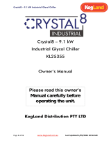
See in the picture the minimum distances (in m) that must be left around the
Ultracool unit.

- -
5
2
Installation
A
B
C
D
E
Minimum distance m (in)
2 (79”)
2 (79”)
2 (79”)
2 (79”)
H+2 (H+79”)
In case of installation in a small room it is imperative that the room, has an
appropriate ventilation system to evacuate all the heat generated by the chiller
as explained before on this same point. If the heat is not removed the
temperature in the room will quickly increase beyond the operating limits of the
unit and it will stop by high pressure alarm.
The Ultracool units must always operate with the panels closed to enable
the inlet of fresh air only through the condenser.
Fig.1
Fig.2
Max. 3m (10 feet) total pipe length and 1 round elbow
Rectangular pipe min. 650 mm (26”) x 1500 mm (69’’)
A
B
C
D
E
H

- -
6
2
Installation
2.4 Identification Labels on the Ultracool unit
You can find the following labels stuck on the Ultracool unit:
2.5 Water Connection
The water connection of the Ultracool unit must be carried out according to the
indications of the labels (stickers) onto the unit.
Minimize the number of bends in the water lines. The length of pipe, number
of fittings, valves, etc. will also cause an increase of the pressure drop.
The chiller should be located as close as possible to the application. Pressure
drop in the pipe should not exceed 0.7 bar.
To perform the water connections make sure the chiller is turned Off and
disconnected from any power supply and open the lateral and back panels
of the chiller.
Always install thermal insulation for all pipes or, at least, make sure that
the pipes are opaque to the light.
Water inlet from the installation to
the Ultracool unit (UC-0300/0650
inside the housing).
Water outlet from the Ultracool
unit to the installation (UC-
0300/0650 inside the housing).
Drain ( UC-
0300/0650 inside
the housing).
Connection for the tank
overflow (UC-0300/0650
inside the housing).
Power supply
depending on version.
Danger of cuts!
Completely disconnect
the chiller power supply
before opening this cover.
Indicative arrow showing the pump
turn direction (UC-0800/2400 inside
the unit).
Connection to fill the tank
(Only UC-0800/2400).

- -
7
When possible install the water lines at the same level as the chiller until
reaching the application The height difference between the chiller and the
application should never exceed 10m (33 feet). In the installations in which
the water level of the circuit exceeds the maximum level of the tank
inside the Ultracool unit, it will be necessary to install a check valve in
the water outlet of the Ultracool unit and a solenoid valve in the water
inlet. The power supply of this solenoid valve will be carried out by terminals
designed for that purpose (see electrical diagrams).
To prevent rusting of the water pipes, we recommend plastic pipes and plastic
or brass fittings.
Where flexible tubing is used, it should be of reinforced construction and rating
for a minimum working pressure of 10 bar g (145 psig) within -5ºC and 30ºC
(23ºF and 86ºF).
Superplus models (only UC-0800/2400): It is mandatory to install a manual
valve at the chiller’s water inlet and one at the chiller’s water outlet.
Standard models: The user pump must provide the chiller with the flow
indicated in the Ultracool characteristics plate (see Technical specifications
sheet). Take into account that the maximum pressure at the chiller’s inlet
cannot exceed 10 bar (145 psi).
Standard with pump models: If the pump is to draw liquid from a level lower
than the pump suction port, a foot/non-return valve must be fitted to the water
inlet from the installation to the Ultracool unit.
2.5.1 Ultracool 0300/0650 Water Connection
The water lines must be pipes of at least 1 ½”.
2
Installation
1.- Enclosed with the chiller are supplied the
necessary fittings to make the inlet and
outlet process water connections. For each
connection there are:
- Gasket D.43/58 X 3
- 2”1½” Quick threaded connection
- 1½” F-F Fitting
- 1½” x 40 Hose carrier
-
-
-
-
2.- Assemble the fittings according to picture 2 and insert them into
the inlet and outlet hoses for the process water.
1
2
2

- -
8
2.5.2 Ultracool 0800/2400 Water Connection
The diameters of the inlet and outlet lines must be the same size or larger than
those corresponding to the water inlet and outlet of the Ultracool unit.
2
Installation
3.- Introduce the inlet and outlet water hoses
with the corresponding fittings already
assembled inside the chiller housing through
the connection port. There are two connection
ports available at back panel (see dimensional
diagram at the end of the manual): Process
water circuit and drain & overflow tap.
4.- Connect the inlet water hose coming from
the application to the 2” nipple located at the
inlet of the water filter.
6.- Connect a hose to the drain and overflow
connection located at the bottom of the water
tank. Use a flexible hose with 10mm internal
diameter.
6
4
3
5.- Connect the outlet water hose going to
the application to the 2” nipple located at the
pump outlet (superplus models) or
evaporator outlet (standard models). See the
identification labels.
Connect the fittings of the inlet/outlet
using a wrench and counter wrench in
order to avoid forcing the water
components of the chiller.
5

- -
9
2.6 Electrical Connection
Operating voltage: 400VAC +/-10%, 50Hz, 3 Ph or 460VAC +/-10% 60Hz, 3 Ph
depending on the version. It must be checked that the supply voltage does not
exceed a maximum variation of 10% referring to nominal.
The electrical design of Ultracool unit is according to EN-60204 norms.
For the electric supply to the Ultracool unit use an appropriate electrical line
according to the data in the characteristics plate.
The chiller has some special terminals prepared for the following functions:
- Terminals 23 and 24, remote On/Off operation: The Ultracool unit can be
turned On and Off automatically by an external signal. This remote On/Off
signal can be transmitted to these terminals by a dry contact in the
application or by a remote switch (open contact = chiller Off, closed contact
= chiller On).
Note: During the initial commissioning, the Ultracool unit must stay
turned Off but connected to the power supply (Main power switch On)
for at least 6 hours (see point 3.2). During this time the Ultracool unit
must not receive any On signal; do not connect the wire bridge
supplied between terminals 23 and 24 yet. If the remote On/Off
function is being used do not send any On signal to the chiller yet.
- Terminals 25 and 26, external solenoid valve connection (only for
superplus models): See electrical diagram for the correct power supply for
the solenoid valve. If the pipes of the application are installed above the
level of the chiller’s outlet this valve prevents backflow when the chiller is
stopped (see point 2.5). These terminals only receive power supply when
the water pump is working.
- Terminals 56 and 57, unit On/Off indicator: These terminals provide a dry
contact to indicate when the unit is turned on or turned off. This contact is
open as long as the Ultracool unit is turned off.
- Terminals 57 and 61, external alarm report signal: These terminals
provide a dry contact for a general alarm of the chiller. This contact can be
adjusted in order to open or close when there is an alarm (see section
4.2.1).
A system of fuses or circuit breakers must be installed before the
power inlet connection to the Ultracool unit. The maximum size of
these protections is defined in the Ultracool characteristics plate.
2
Installation

- -
10
3
Start-up
3 Start-up
3.1 Operating Conditions
The control thermostat in the chiller will control it in order to maintain the preset
cold water temperature.
Water temperature at the inlet:
Nominal:
15ºC (59ºF)
Maximum:
35ºC (95ºF)
Cold water temperature at the outlet:
Nominal:
10ºC (50ºF)
Minimum:
7ºC (45ºF) (1)
Maximum:
25ºC (77ºF)
Temperature of the ambient air:
Nominal:
25ºC (77ºF)
Minimum:
0ºC (32ºF) / -15ºC (5ºF) with speed regulator option (2)
Maximum:
45ºC (113ºF)
(1) The Ultracool units can work with cold water temperatures lower than 7ºC
(45ºF). To do so, add ethylene glycol to the water and contact an authorized
technical service to adjust the chiller.
(2) In order to work at temperatures lower than 0ºC (32ºF) it is necessary to
add ethylene glycol to the water and contact an authorized technical service to
adjust the chiller. The units can work below 0ºC (32ºF) by using the speed
regulator option. The minimum ambient temperature with this option is –15ºC
(5ºF).
Only an authorized technical service can adjust the antifreeze set point.
The following table shows the ethylene glycol concentration and the
antifreeze adjustment required:
Glycol concentration
(3) and antifreeze
adjustment
Min Ambient Temperature
0ºC or more
Less than 0ºC
until -5ºC
Less than -5ºC
until -15ºC
Cold Water
Set Point
7ºC or more
0%
0ºC
15%
-5ºC
30%
-15ºC
Less than
7ºC until 5ºC
15%
-5ºC
15%
-5ºC
30%
-15ºC
Less than
5ºC until 0ºC
30%
-15ºC
30%
-15ºC
30%
-15ºC
Less than
0ºC until -5ºC
30%
-15ºC
30%
-15ºC
30%
-15ºC

- -
11
3
Start-up
Glycol concentration
(3) and antifreeze
adjustment
Min Ambient Temperature
32ºF or more
Less than 32ºF
until 23ºF
Less than 23ºF
until 5ºF
Cold Water
Set Point
45ºF or more
0%
32ºF
15%
23ºF
30%
5ºF
Less than 45ºF
until 41ºF
15%
23ºF
15%
23ºF
30%
5ºF
Less than 41ºF
until 32ºF
30%
5ºF
30%
5ºF
30%
5ºF
Less than 32ºF
until 23ºF
30%
5ºF
30%
5ºF
30%
5ºF
(3) The ethylene glycol percentage is given as % measured as weight of the total
mixture. In case of any modification in the quantity of water in the installation, the
concentration of ethylene glycol should be checked.
If more volume is required it is necessary to keep the ethylene glycol concentration
Do not use automotive antifreeze. Use lab grade ethylene glycol only!
Do not use an ethylene glycol concentration above 30%; this would
damage the water pump.
3.2 Chiller start-up
Clean the application water circuit with tap water in order to be sure that there
are no free particles. Otherwise the filter element can block up during the start
up process.
Turn Off the Main power switch (to avoid any possibility of unexpected start
up of the equipment during this operation). Open the lateral and back panels,
open the tank cover and fill the tank with water of the required quality (see
annex 9), the suitable glycol concentration according to point 3.1 of this
manual and all the Refrifluid B additive supplied with the chiller (2 liters
per each 100 liters of water tank volume). Fill the mixture directly to the tank
or using the filling port (only UC-0800 to 2400) until the maximum level of the
tank is reached.
In superplus models, check that the level switch has switched to the “full”
position (you will feel it “click” if you lift by the hand).
Prime the pump in order to release any air inside,
in superplus models:
1. Remove the priming plug (P, see diagram below).
2. Keep the priming plug open until only liquid runs out the priming plug.
3. Replace the priming pump and tighten securely.
in standard with pump models:
1. Close the external manual valve at the Ultracool outlet.
2. Remove the priming plug (P, see diagram below).

- -
12
3. Pump priming:
a. If the liquid level in the tank is below the pump inlet: Pour water
through the priming port. Make sure that the suction pipe and pump
are completely filled and vented.
b. If the liquid level in the tank is above the pump inlet: Keep the
priming plug open until only liquid runs out the priming plug.
4. Replace the priming plug and tighten securely.
5. Open the external manual valve at the Ultracool outlet.
Do not start the Ultracool unit until the pump has been properly vented.
Open the water inlet valve completely and close the outlet water valve
completely as shown on the following pictures for UC-0300 to 0650. On UC-
0800 to 2400 do the same with the water inlet and outlet valves installed.
Make sure that the external fuses are installed. See electrical diagram.
Make sure that the Remote On/Off control is not connected between terminals
23 and 24 and a wire-bridge is not installed between them either.
When the Ultracool unit is started for the first time, it is necessary to turn On the
Main power switch (element 1 in the control panel, see point 4) and wait six
hours before continuing with the start-up sequence. This time is necessary for
the crankcase of the compressor to heat up. The compressor can be
damaged if this procedure is not followed.
Close the lateral and back panels and switch OFF the main power switch
during any electrical intervention.
3
Start-up

- -
13
Connect the Remote ON/OFF control in terminals 23 and 24 (see point 2.6). If
you do not use a remote control, connect the wire-bridge supplied inside the
electrical box to link terminals 23 and 24.
Switch ON the general switch and, if necessary, give an ON signal through the
remote ON/OFF, then the unit will start up.
In superplus models: Check that the working pressure of the pump is higher
than nominal pressure indicated at the characteristics plate. If it is below this
value the pump is turning in the wrong direction. If this happens, switch OFF
the main power switch, disconnect the chiller from the power supply and
exchange two phases in the main power supply. It will not be necessary to
check the turn direction of the fans, because they are delivered in phase with
the pumps. Since it may be difficult to see the pump’s rotation direction, verify
that you did this operation correctly when the motor fans start working: The air
should enter the condenser and go out through the top of the Ultracool unit. If
the air is moving in the opposite direction then exchange two phases in the main
power supply.
Pump pressure adjustment UC-0300 to 0650:
Increase the cold water set point up to the maximum allowed value (see point 4)
to prevent the compressor from starting. Switch the main power switch OFF and
then back ON. Open the lateral and back panel and adjust the water outlet
valves so the pump works at the nominal pressure indicated in the chiller’s data
plate.
If the water tank temperature is above the programmed
setpoint, the compressor will start 1 minute after switching
the main power switch ON. If this happens switch the main
power switch OFF and perform the operation again within 1
minute. If the compressor works with the lateral and/or back
panel open the chiller will trip by high pressure alarm, see
point 6.
Pump pressure adjustment UC-0800 to 2400:
Adjust the outlet valve so the pump works at the nominal pressure indicated in
the chiller’s data plate.
After 5 minutes stop the unit, open the left and back panels (only UC-
0300/0650) and check the level in the tank. If the level is below the maximum
then refill the water tank again. Repeat this operation until water level in the
tank remains constant.
When refilling the tank respect the ethylene glycol concentration as per
point 3.1.
In the standard models, it will be necessary to check the direction of
rotation of the compressor. To do so, wait until the compressor starts up. If
the direction of rotation is wrong then the compressor produces a loud and
disgusting noise. Moreover, as the compressor is not compressing the
refrigerant, the high pressure gauge (see element 5 point 4.1) will not increase
its pressure and the low pressure gauge (see element 6 point 4.1) will not
3
Start-up

- -
14
decrease its pressure. In this case exchange two phases in the main power
supply.
Once the two phases are changed, check the turn direction of the fans, because
they are delivered in phase with the compressor. Verify that you did this
operation correctly when the motor fans start working: The air should enter the
condenser and go out through the top of the Ultracool unit. If the air is moving in
the opposite direction then exchange two phases in the main power supply.
On the control thermostat select the desired temperature of the cold water outlet
(see point 4.2.1). The Ultracool units are delivered with a pre-set temperature of
10ºC (50ºF).
If the pump pressure is higher than the Pnom. value indicated in the
characteristics plate and the outlet manual valve is already fully open,
check that all manual valves in the circuit are fully open. If the pressure is
still above Pnom. then check that the water pipes meet the requirements
on point 2.5.
3
Start-up

- -
15
4
Control Panel
4 Control Panel
Pressure gauges
Control Panel
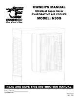
4.1 Components of the Control Panel
The control panel includes of the following elements:
1. Main power switch: connects and disconnects the Ultracool unit from the
power supply.
2. Water pressure gauge: indicates the pressure supplied by the pump
(superplus and standard with pump models) or the pressure at the inlet (standard
models).
4. Water filter pressure gauge: indicates the pressure drop of the water filter and
the evaporator (superplus models), or the water outlet pressure (standard models).
5. High pressure gauge: indicates the pressure at the high-pressure side of the
refrigerating circuit (after the compressor). Models from UC-0800 to UC-2400, that
have two refrigerating circuits, have also two pressure gauges.
6. Low pressure gauge: indicates the pressure at the low-pressure side of the
refrigerating circuit (before the compressor). Models from UC-0800 to UC-2400,
that have two refrigerating circuits, have also two pressure gauges.
7. Control thermostat: indicates the cold water temperature at the outlet of the
Ultracool unit and enables it to be regulated.
7
2
1
4
1
5
6

- -
16
Water
pump on
indicator
Fridge
compressor
on indicator
Glycol
warning
Alarm
indicator
Prg
Up
Sel
Down
4.2 Control Thermostat
4.2.1 Operation
As long as the main power switch is on, the display of the control
thermostat shows the water temperature measured in the water tank. In the
50Hz version the display shows the temperature in ºC and in the 60Hz
version it shows it in ºF.
Remote On/Off: The chiller cannot be started without an On signal through
Remote On/Off control from the application (circuit closed between terminals 23
and 24). See point 2.6.
On/Off memory: The control thermostat comes back to the last mode/status
(“On” or “Stand by”) at which the control thermostat it was powered off the last
time. This means that, if the chiller was initially in Standby mode, if you turn Off
and On the Main Power Switch, the chiller will still continue in Standby instead of
turning On automatically.
To start the chiller again you should give an On signal locally through the
thermostat keypad, with the UP key as indicated above or remotely through
remote On/Off terminals 23 and 24.
Local On/Off: As long as the remote On/Off is connected, the chiller can be also
turned On and Off locally through the control thermostat keypad. In order to
start/stop the chiller press the UP button during a few seconds. When the chiller
turns On the On/Off indicator signal is lit in the thermostat display as depicted
above.
Temperature probe reading: During normal thermostat operation, pressing Up
for less than 5 seconds allows displaying the current values of the different
probes of the chiller. In this mode, pressing UP and DOWN selects the probe and
pressing SEL displays the value of the selected probe.
To exit this mode, press PRG button or do not press any button for at least 60
seconds.
4
Control Panel
A
l
a
r
m
i
A
l
a
r
m
i
n
d
i
c
a
t
o
Compressor
timer indicator
On/Off indicator
A
l
a
r
m
i

- -
17
Setting the temperature: to introduce the required working temperature
(between -5ºC (23ºF) and 20ºC (68ºF) use the following procedure:
- Press Sel button for about 5 seconds, the display will show "- / -".
- Press Down button several times until the display shows "- r -".
- Press Sel button and the display will show "r01". This parameter is the
setpoint.
- Press Sel button to display the current setpoint value.
- To increase or to decrease the value of the setpoint, use the Up and Down
buttons.
- Press Sel button to confirm the new value. The display will show "r01".
- Press Prg button three times to exit the setpoint modification procedure.
The display will show again the water tank temperature.
1. On/Off indicator: it indicates when the chiller is turned On.
2. Alarm indicator: this is lit when there is an alarm. Depending on the alarm it can
cause fridge circuit or all the Ultracool unit to stop. The display will show the
alarm code:
Alarm code FL: Low water level alarm or pump overload.
Alarm code A1: Circuit 1 antifreeze alarm.
Alarm code A2: Circuit 2 antifreeze alarm.
Alarm code tC1: Circuit 1 overload alarm.
Alarm code tC2: Circuit 2 overload alarm.
Alarm code LP1: Circuit 1 low refrigerant pressure.
Alarm code LP2: Circuit 2 low refrigerant pressure.
Alarm code HP1: Circuit 1 high refrigerant pressure.
Alarm code HP2: Circuit 2 high refrigerant pressure.
Alarm code Ht: High water temperature.
Alarm code E1, E2, E3, E6: Temperature sensor disconnected, short-
circuited or faulty.
Alarm code EPr : EEPROM error during operation.
Alarm code EPb: EEPROM error at start-up.
Alarm code ELS: Low supply voltage.
Alarm code EHS: High supply voltage.
Alarm code EL1: Electromagnetic noise detected in the power supply.
Alarm code Hc1, Hc2, Hc3, Hc4: Maintenance warning.
3. External alarm contact adjustment (see electrical diagram):
The UC unit has two terminals that provide a dry contact for a general alarm of
the chiller. In order to modify the behaviour of this contact it is necessary to
modify the value of the following control thermostat parameter:
If P21=0 (default value): The contact closes when there is an active alarm
If P21=1: The contact opens when there is an active alarm.
The procedure to modify the P21 parameter is the following:
- Press for about 5 seconds the button Sel and the display will show "- / -".
- Press DOWN button until the display shows "- P -".
- Press Sel button and the display will show "P21".
- Press Sel button.
- To adjust the P21 value to 0 or 1, use the UP and DOWN buttons.
- Press Sel button to confirm the new value. The display will show "P21".
- Press Prg button three times to exit the modification procedure.
4
Control Panel

- -
18
3. Glycol warning: this indicator is lit when the working conditions of the chiller
require ethylene glycol as antifreeze agent in the water circuit to avoid freezing. Be
sure that the water mixture has the suitable ethylene glycol concentration when this lit
is on. Please check point 3.1 from this manual to adjust the ethylene glycol
concentration of the water mixture according to the ambient temperature and
antifreeze set point.
4. Pump On indicator: this remains lit when the pump is working.
5. Compressor On indicator: this remains lit when at least one of the
compressors is working.
6. Compressor timer indicator: When “1” , “2”, “3” or “4” blinks it means that the
thermostat is delaying the compressors start up. Once a compressor starts the
number stays lit fix on the display.
4
Control Panel

- -
19
5
Maintenance
5 Maintenance
5.1 Basic Maintenance
Weekly:
Verify that the water temperature indicated on the control thermostat is
approximately at the setpoint.
Verify that the pressure of the pump is the same as the nominal pressure (Pnom)
indicated in the characteristics plate.
Verify the water level in the tank.
Verify the state of the water filter element; if the pressure drop exceeds 1,5 bar
(22 psi), change the filter element (the filter is installed at the water inlet line
inside the chiller).
Monthly:
With the Unit disconnected (Main power switch OFF), clean the condenser with a
blast of compressed air, from the inside towards the outside.
Clean the housing, internally and externally, eliminating the dust present
especially on the water pump rack.
Yearly:
Change the filter element and refill the water circuit with water of the required
quality (see annex 9), the suitable glycol concentration according to point 3.1 of
this manual and the Refrifluid B additive supplied with the chiller (2 liters per each
100 liters of water tank volume).
Preventive maintenance warning (Hc1, Hc2, Hc3 or Hc4)
The control thermostat has a preventive maintenance warning based on the
working hours. When this warning appears, contact an authorised technical
service to perform the preventive maintenance.
/