Page is loading ...

IS-44342LED-US
We’re here to help 866-558-5706
Hrs: M-F 9am to 5pm EST
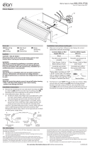
1) Aach mounng strap[A] to outlet box[D] using the
strap mounng screws[B]. Mounng strap can be
adjusted to suit posion of xture.
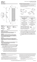
2) Grounding instrucons: (See Illus. a or b).
a) On xtures where mounng strap is provided with a
hole and two raised dimples, wrap ground wire from
outlet box around green ground screw, and thread
into hole.
b) On xtures where a cupped washer is provided,
aach ground wire from outlet box under cupped
washer and green ground screw, then thread into
mounng strap.
If xture is provided with ground wire, connect xture
ground wire to outlet box ground wire with wire
connector aer following the above steps. Never connect
ground wire to black or white power supply wires.
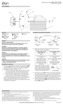
3) Make wire connecon. Reference chart below for correct
connecons and wire accordingly.
Connect Black or Red
Supply Wire to:
Connect White Supply
Wire to:
Black White
*Parallel cord (round &
smooth)
*Parallel cord (square &
ridged)
Clear, Brown, Gold or
Black without Tracer
Clear, Brown, Gold or Black
with Tracer
Insulated wire (other
than green) with copper
conductor
Insulated wire (other
than green) with silver
conductor
*Note: When parallel wire (SPT
1 & SPT 2) are used. The neutral
wire is square shaped or ridged
and the other wire will be round
in shape or smooth (See illus.)
Neutral Wire
4) Push xture[C] to ceiling. NOTE: Be certain wires do not
get pinched between canopy[H] and ceiling.
5) Use the two (2) at head screws[E] to secure the canopy
to the ceiling by threading into the sides of the canopy.
Tighten to secure.
6) Carefully install the glass[F] by raising up to the sides and
using the decorave knobs[G] secure the glass into place
as shown.
GREEN GROUND
SCREW
CUPPED
WASHER
OUTLET BOX
GROUND
FIXTURE
GROUND
DIMPLES
WIRE CONNECTOR
OUTLET BOX
GROUND
GREEN GROUND
SCREW
FIXTURE
GROUND
a
b
Fixture Diagram
Parts List
[A] Mounting
Strap
[B] Strap
Mounting
Screws
[C] Fixture
[D] Outlet Box
[E] Flat Head
Screws
[F] Glass
[G] Decorative
Knobs
[H] Canopy
Cauons
CAUTION – RISK OF SHOCK –
Disconnect Power at the main circuit breaker panel or main
fusebox before starng and during the installaon.
WARNING:
This xture is intended for installaon in accordance with the
Naonal Electrical Code (NEC) and all local code specicaons.
If you are not familiar with code requirements, installaon by a
cered electrician is recommended.
DIMMING:
This LED xture is compable with most standard incandescent
dimmers, LED dimmers, and electronic low voltage dimmers.
For opmal performance, an electronic low voltage dimmer should
be used.
CLEANING:
Always be certain that electric current is turned o before cleaning.
• Only a so damp cloth should be used. Harsh cleaning
products may damage the nish.
Installaon Instrucons
This device complies with part 15 of the FCC Rules. Operaon is
subject to the following two condions:
1) This device may not cause harmful interference, and
2) This device must accept any interference received, including
interference that may cause undesired operaon.
Note: This equipment has been tested and found to comply with
the limits for a Class B digital device, pursuant to part 15 of the FCC
Rules. These limits are designed to provide reasonable protecon
against harmful interference in a residenal installaon. This
equipment generates, uses and can radiate radio frequency energy
and, if not installed and used in accordance with the instrucons,
may cause harmful interference to radio communicaons. However,
there is no guarantee that interference will not occur in a parcular
installaon. If this equipment does cause harmful interference to
radio or television recepon, which can be determined by turning
the equipment o and on, the user is encouraged to try to correct
the interference by one or more of the following measures:
• Reorient or relocate the receiving antenna.
• Increase the separaon between the equipment and receiver.
• Connect the equipment into an outlet on a circuit dierent from
that to which the receiver is connected.
• Consult the dealer or an experienced radio/TV technician for
help.
FCC Information:
A
C
B
H
E
G
F
G
F
D

IS-44342LED-CB
We’re here to help 866-558-5706
Hrs: M-F 9am to 5pm EST
1) Aach mounng strap[A] to outlet box[D] using the
strap mounng screws[B]. Mounng strap can be
adjusted to suit posion of xture.
2) Grounding instrucons: (See Illus. a or b).
a) On xtures where mounng strap is provided with a
hole and two raised dimples, wrap ground wire from
outlet box around green ground screw, and thread
into hole.
b) On xtures where a cupped washer is provided,
aach ground wire from outlet box under cupped
washer and green ground screw, then thread into
mounng strap.
If xture is provided with ground wire, connect xture
ground wire to outlet box ground wire with wire
connector aer following the above steps. Never connect
ground wire to black or white power supply wires.
3) Make wire connecon. Reference chart below for correct
connecons and wire accordingly.
Connect Black or Red
Supply Wire to:
Connect White Supply
Wire to:
Black White
*Parallel cord (round &
smooth)
*Parallel cord (square &
ridged)
Clear, Brown, Gold or
Black without Tracer
Clear, Brown, Gold or Black
with Tracer
Insulated wire (other
than green) with copper
conductor
Insulated wire (other
than green) with silver
conductor
*Note: When parallel wire (SPT
1 & SPT 2) are used. The neutral
wire is square shaped or ridged
and the other wire will be round
in shape or smooth (See illus.)
Neutral Wire
4) Push xture[C] to ceiling. NOTE: Be certain wires do not
get pinched between canopy[H] and ceiling.
5) Use the two (2) at head screws[E] to secure the canopy
to the ceiling by threading into the sides of the canopy.
Tighten to secure.
6) Carefully install the glass[F] by raising up to the sides and
using the decorave knobs[G] secure the glass into place
as shown.
GREEN GROUND
SCREW
CUPPED
WASHER
OUTLET BOX
GROUND
FIXTURE
GROUND
DIMPLES
WIRE CONNECTOR
OUTLET BOX
GROUND
GREEN GROUND
SCREW
FIXTURE
GROUND
a
b
Fixture Diagram
Parts List
[A] Mounting
Strap
[B] Strap
Mounting
Screws
[C] Fixture
[D] Outlet Box
[E] Flat Head
Screws
[F] Glass
[G] Decorative
Knobs
[H] Canopy
Cauons
CAUTION – RISK OF SHOCK –
Disconnect Power at the main circuit breaker panel or main
fusebox before starng and during the installaon.
WARNING:
This xture is intended for installaon in accordance with the
Naonal Electrical Code (NEC) and all local code specicaons.
If you are not familiar with code requirements, installaon by a
cered electrician is recommended.
DIMMING:
This LED xture is compable with most standard incandescent
dimmers, LED dimmers, and electronic low voltage dimmers.
For opmal performance, an electronic low voltage dimmer should
be used.
CLEANING:
Always be certain that electric current is turned o before cleaning.
• Only a so damp cloth should be used. Harsh cleaning
products may damage the nish.
Installaon Instrucons
This device complies with part 15 of the FCC Rules. Operaon is
subject to the following two condions:
1) This device may not cause harmful interference, and
2) This device must accept any interference received, including
interference that may cause undesired operaon.
Note: This equipment has been tested and found to comply with
the limits for a Class B digital device, pursuant to part 15 of the FCC
Rules. These limits are designed to provide reasonable protecon
against harmful interference in a residenal installaon. This
equipment generates, uses and can radiate radio frequency energy
and, if not installed and used in accordance with the instrucons,
may cause harmful interference to radio communicaons. However,
there is no guarantee that interference will not occur in a parcular
installaon. If this equipment does cause harmful interference to
radio or television recepon, which can be determined by turning
the equipment o and on, the user is encouraged to try to correct
the interference by one or more of the following measures:
• Reorient or relocate the receiving antenna.
• Increase the separaon between the equipment and receiver.
• Connect the equipment into an outlet on a circuit dierent from
that to which the receiver is connected.
• Consult the dealer or an experienced radio/TV technician for
help.
FCC Information:
A
C
B
H
E
G
F
G
F
D
/