Page is loading ...

IS-45723LED-US
We’re here to help 866-558-5706
Hrs: M-F 9am to 5pm EST
E
G
BC
D
A
F
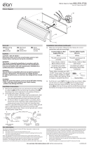
1) Aach mounng strap[A] to outlet box[B] using the strap
mounng screws[C]. Mounng strap can be adjusted to suit
posion of xture.
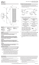
2) Grounding instrucons: (See Illus. a or b).
a) On xtures where mounng strap is provided with a hole
and two raised dimples, wrap ground wire from outlet
box around green ground screw, and thread into hole.
b) On xtures where a cupped washer is provided, aach
ground wire from outlet box under cupped washer and
green ground screw, then thread into mounng strap.
If xture is provided with ground wire, connect xture ground
wire to outlet box ground wire with wire connector aer
following the above steps. Never connect ground wire to black
or white power supply wires.
3) Make wire connecon. Reference chart below for correct
connecons and wire accordingly.
Connect Black or Red
Supply Wire to: Connect White Supply
Wire to:
Black White
*Parallel cord (round &
smooth)
*Parallel cord (square &
ridged)
Clear, Brown, Gold or
Black without Tracer
Clear, Brown, Gold or Black
with Tracer
Insulated wire (other
than green) with copper
conductor
Insulated wire (other
than green) with silver
conductor
*Note: When parallel wire (SPT
1 & SPT 2) are used. The neutral
wire is square shaped or ridged
and the other wire will be round
in shape or smooth (See illus.) Neutral Wire
4) Push xture to wall. NOTE: Fixture can be mounted with glass
in the up or down posion. NOTE: Make sure all wires are
inside canopy and do not get pinched between canopy and
wall.
5) Use the two (2) at head screws[E] to secure the canopy to
the wall by threading into the sides of the canopy[D]. Tighten
to secure.
6) Carefully install the glass[F] by gently lowering onto the main
body[G] and rotate into place as shown.
GREEN GROUND
SCREW
CUPPED
WASHER
OUTLET BOX
GROUND
FIXTURE
GROUND
DIMPLES
WIRE CONNECTOR
OUTLET BOX
GROUND
GREEN GROUND
SCREW
FIXTURE
GROUND
ab
Fixture Diagram
Parts List
[A] Mounting
Strap
[B] Outlet Box
[C] Strap
Mounting
Screws
[D] Canopy
[E] Flat Head
Screws
[F] Glass
[G] Main Body
Cauons
CAUTION – RISK OF SHOCK –
Disconnect Power at the main circuit breaker panel or main
fusebox before starng and during the installaon.
WARNING:
This xture is intended for installaon in accordance with the
Naonal Electrical Code (NEC) and all local code specicaons.
If you are not familiar with code requirements, installaon by a
cered electrician is recommended.
DIMMING:
This LED xture is compable with most standard incandescent
dimmers, LED dimmers, and electronic low voltage dimmers.
For opmal performance, an electronic low voltage dimmer should
be used.
CLEANING:
Always be certain that electric current is turned o before cleaning.
• Only a so damp cloth should be used. Harsh cleaning
products may damage the nish.
Installaon Instrucons
This device complies with part 15 of the FCC Rules. Operaon is
subject to the following two condions:
1) This device may not cause harmful interference, and
2) This device must accept any interference received, including
interference that may cause undesired operaon.
Note: This equipment has been tested and found to comply with
the limits for a Class B digital device, pursuant to part 15 of the FCC
Rules. These limits are designed to provide reasonable protecon
against harmful interference in a residenal installaon. This
equipment generates, uses and can radiate radio frequency energy
and, if not installed and used in accordance with the instrucons,
may cause harmful interference to radio communicaons. However,
there is no guarantee that interference will not occur in a parcular
installaon. If this equipment does cause harmful interference to
radio or television recepon, which can be determined by turning
the equipment o and on, the user is encouraged to try to correct
the interference by one or more of the following measures:
• Reorient or relocate the receiving antenna.
• Increase the separaon between the equipment and receiver.
• Connect the equipment into an outlet on a circuit dierent from
that to which the receiver is connected.
• Consult the dealer or an experienced radio/TV technician for
help.
FCC Information:

IS-45723LED-US
Estamos aquí para ayudarle 866-558-5706
Horario: Lunes-Viernes 9am a 5pm EST (hora ocial del este)
1) Fije la correa de montaje[A] a la caja de salida[B] con los
tornillos de montaje de la correa[C]. La correa de montaje se
puede ajustar para adaptarse a la posición del aparato.
2) Instrucciones de conexión a erra solamente para los
Estados Unidos. (Vea la ilustracion I o II).
a) En las lámparas que enen el eje, de montaje con un
agujero y dos hoyuelos realzados, enrollar el alambre a
erra de la caja tomacorriente alrededor del tornillo verde
y pasarlo por el aquiero.
b) En las lámparas con una arandela acopada, jar el alambre
a erra de la caja tomacorriente del ajo de la arandela
acoada y tornillo verde, y paser por el eje de montaje.
Si la lámpara viene con alambre a erra, conecter el alambre a
erra de la lámpara al alambre a erra de la caja
tomacorriente con un conector de alambres espués de seguir
los pasos anteriores. Nunca conectar el alambra a erra a los
alambres eléctros negro o blanco.
3) Haga les conexiones de los alambres. La tabla de referencia
de abajo indica las conexiones correctas y los alambres
correspondientes.
Conectar el alambre de
suministro negro o rojo al
Conectar el alambre de
suministro blanco al
Negro Blanco
*Cordon paralelo (redondo y liso) *Cordon paralelo (cuadrado y
estriado)
Claro, marrón, amarillio o negro
sin hebra idencadora
Claro, marrón, amarillio o negro
con hebra idencadora
Alambre aislado (diferente del
verde) con conductor de cobre
Alambre aislado (diferente del
verde) con conductor de plata
*Nota: Cuando se uliza alambre paralelo
(SPT 1 y SPT 2). El alambre neutro es
de forma cuadrada o estriada y el otro
alambre será de forma redonda o lisa.
(Vea la ilustracíón). Hilo Neutral
4) Empuje el artefacto contra la pared. NOTA: El artefacto puede
instalarse con el vidrio hacia arriba o hacia abajo. NOTA:
Asegúrese de que todos los cables estén dentro del escudete y
no pellizcado entre el escudete y la pared.
5) Use los dos (2) tornillos de cabeza plana[E] para asegurar
el escudete a la pared atornillándolos en los costados del
escudete[D]. Ajuste para asegurar.
6) Instale el vidrio[F] bajándolo cuidadosamente hacia el cuerpo
principal[G] y rótelo en su lugar como se indica.
ARANDELA
CONCAVA
TIERRA DE LA
CAJA DE SALIDA
TORNILLO DE TIERRA,
VERDE
DEPRESIONES
TIERRA
ARTEFACTO
CONECTOR DE ALAMBRE
TIERRA DE LA
CAJA DE SALIDA
TORNILLO DE TIERRA,
VERDE
TIERRA
ARTEFACTO
ab
Diagrama de Accesorios
Lista de Partes
[A] Correa de
Montaje
[B] Caja de Salida
[C] Tornillos de
Montaje de la
Correa
[D] Escudete
[E] Tornillos de
Cabeza Plana
[F] Vidrio
[G] Cuerpo
Principal
Precauciones
PRECAUCIÓN – RIESGO DE DESCARGA ELÉCTRICA –
Desconecte la electricidad en el panel principal del interruptor
automáco o caja principal de fusibles antes de comenzar y
durante la instalación.
ADVERTENCIA:
Este accesorio está desnado a la instalación de acuerdo con el
Naonal Electrical Code (NEC) y todas las especicaciones del
código local. Si no está familiarizado con los requisitos del código,
la instalación se recomienda un electricista cercado.
REGULACIÓN DE INTENSIDAD DE LUZ:
Este artefacto LED es compable con la mayoría de los reguladores
de intensidad incandescentes estándares, los reguladores de
intensidad LED, y los reguladores de intensidad de bajo voltaje
electrónicos. Para un desempeño ópmo, debería usarse un
regulador de intensidad de bajo voltaje electrónico.
LIMPIEZA:
Asegúrese siempre de que la corriente eléctrica esté apagada antes
de limpiar.
• Debe usarse solamente un paño húmedo y suave. Productos de
limpieza abrasivos pueden dañar el acabado.
Instrucciones de Instalación
Este disposivo cumple con la parte 15 de las Reglas de la FCC. La
operación es sujeto a las dos condiciones siguientes:
1) Este disposivo no puede causar interferencia dañina, y
2) Este disposivo debe aceptar cualquier interferencia
recibida, incluyendo interferencias que puedan causar un
funcionamiento no deseado.
Nota: Este equipo ha sido probado y cumple con los límites para
un disposivo digital de Clase B, de acuerdo con la parte 15 de
las Reglas de la FCC. Estos límites están diseñados para proveer
protección razonable contra interferencias dañinas en una
instalación residencial. Este equipo genera, uliza y puede irradiar
energía de radiofrecuencia y, si no se instala y uliza de acuerdo con
las instrucciones, puede causar interferencias en las comunicaciones
por radio. Sin embargo, no hay garanzar que no se produzcan
interferencias en una instalación en parcular. Si este equipo causa
interferencia perjudicial a la recepción de radio o televisión, que
puede determinarse encender y apagar el equipo, se recomienda al
usuario que intente corregir la interferencia mediante una o más de
las siguientes medidas:
• Reorientar o reubicar la antena receptora.
• Aumente la separación entre el equipo y el receptor.
• Conecte el equipo a una toma de corriente en un circuito
disnto al que está conectado el receptor.
• Consulte al distribuidor oa un técnico de radio / TV
experimentado para obtener ayuda.
INFORMACIÓN DE LA FCC:
E
G
BC
D
A
F

IS-45723LED-CB
We’re here to help 866-558-5706
Hrs: M-F 9am to 5pm EST
E
G
BC
D
A
F
1) Aach mounng strap[A] to outlet box[B] using the strap
mounng screws[C]. Mounng strap can be adjusted to suit
posion of xture.
2) Grounding instrucons: (See Illus. a or b).
a) On xtures where mounng strap is provided with a hole
and two raised dimples, wrap ground wire from outlet
box around green ground screw, and thread into hole.
b) On xtures where a cupped washer is provided, aach
ground wire from outlet box under cupped washer and
green ground screw, then thread into mounng strap.
If xture is provided with ground wire, connect xture ground
wire to outlet box ground wire with wire connector aer
following the above steps. Never connect ground wire to black
or white power supply wires.
3) Make wire connecon. Reference chart below for correct
connecons and wire accordingly.
Connect Black or Red
Supply Wire to: Connect White Supply
Wire to:
Black White
*Parallel cord (round &
smooth)
*Parallel cord (square &
ridged)
Clear, Brown, Gold or
Black without Tracer
Clear, Brown, Gold or Black
with Tracer
Insulated wire (other
than green) with copper
conductor
Insulated wire (other
than green) with silver
conductor
*Note: When parallel wire (SPT
1 & SPT 2) are used. The neutral
wire is square shaped or ridged
and the other wire will be round
in shape or smooth (See illus.) Neutral Wire
4) Push xture to wall. NOTE: Fixture can be mounted with glass
in the up or down posion. NOTE: Make sure all wires are
inside canopy and do not get pinched between canopy and
wall.
5) Use the two (2) at head screws[E] to secure the canopy to
the wall by threading into the sides of the canopy[D]. Tighten
to secure.
6) Carefully install the glass[F] by gently lowering onto the main
body[G] and rotate into place as shown.
GREEN GROUND
SCREW
CUPPED
WASHER
OUTLET BOX
GROUND
FIXTURE
GROUND
DIMPLES
WIRE CONNECTOR
OUTLET BOX
GROUND
GREEN GROUND
SCREW
FIXTURE
GROUND
ab
Fixture Diagram
Parts List
[A] Mounting
Strap
[B] Outlet Box
[C] Strap
Mounting
Screws
[D] Canopy
[E] Flat Head
Screws
[F] Glass
[G] Main Body
Cauons
CAUTION – RISK OF SHOCK –
Disconnect Power at the main circuit breaker panel or main
fusebox before starng and during the installaon.
WARNING:
This xture is intended for installaon in accordance with the
Naonal Electrical Code (NEC) and all local code specicaons.
If you are not familiar with code requirements, installaon by a
cered electrician is recommended.
DIMMING:
This LED xture is compable with most standard incandescent
dimmers, LED dimmers, and electronic low voltage dimmers.
For opmal performance, an electronic low voltage dimmer should
be used.
CLEANING:
Always be certain that electric current is turned o before cleaning.
• Only a so damp cloth should be used. Harsh cleaning
products may damage the nish.
Installaon Instrucons
This device complies with part 15 of the FCC Rules. Operaon is
subject to the following two condions:
1) This device may not cause harmful interference, and
2) This device must accept any interference received, including
interference that may cause undesired operaon.
Note: This equipment has been tested and found to comply with
the limits for a Class B digital device, pursuant to part 15 of the FCC
Rules. These limits are designed to provide reasonable protecon
against harmful interference in a residenal installaon. This
equipment generates, uses and can radiate radio frequency energy
and, if not installed and used in accordance with the instrucons,
may cause harmful interference to radio communicaons. However,
there is no guarantee that interference will not occur in a parcular
installaon. If this equipment does cause harmful interference to
radio or television recepon, which can be determined by turning
the equipment o and on, the user is encouraged to try to correct
the interference by one or more of the following measures:
• Reorient or relocate the receiving antenna.
• Increase the separaon between the equipment and receiver.
• Connect the equipment into an outlet on a circuit dierent from
that to which the receiver is connected.
• Consult the dealer or an experienced radio/TV technician for
help.
FCC Information:

IS-45723LED-CB
Nous sommes là pour vous aider 866-558-5706
Heures : du lundi au vendredi, de 9h à 17h (heure de l’Est)
INSTRUCTIONS:
For Assembling and Installing Fixtures in Canada
Pour L’assemblage et L’installaon Au Canada
1) Visser la barree de montage[A] à la boite de
joncon[B] à l’aide des vis de montage de la barree[C].
La barree de montage peut etre ajustée pour convenir à
la posion de l’applique.
2) Connecter les ls. Se reporter au tableau ci-dessous pour
faire les connexions.
Connecter le l noir ou
rouge de la boite Connecter le l blanc de
la boîte
A Noir A Blanc
*Au cordon parallèle (rond
et lisse)
*Au cordon parallèle (à
angles droits el strié)
Au transparent, doré,
marron, ou noir sans l
disncf
Au transparent, doré,
marron, ou noir avec un l
disncf
Fil isolé (sauf l vert) avec
conducteur en cuivre
Fil isolé (sauf l vert) avec
conducteur en argent
*Remarque: Avec emploi d’un
l paralléle (SPT 1 et SPT 2). Le
l neutre est á angles droits ou
strié et l’autre l doit étre rond
ou lisse (Voir le schéma). Fil Neutre
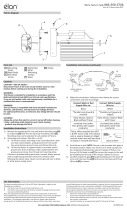
3) Poussez le luminaire contre le mur. REMARQUE : Le luminaire
peut être monté avec le verre en posion vers le haut ou vers
le bas. REMARQUE : Assurez-vous que tous les ls sont
à l’intérieur de la canopée et ne pas être pincés entre la
canopée et le mur.
4) Ulisez les deux (2) vis à tête plate[E] pour xer le cache
au mur en les vissant dans les côtés du cache[D]. Serrez
pour immobiliser.
5) Installez délicatement le verre[F] en l’abaissant
doucement sur le corps du luminaire[G] et tournez-le sur
place tel qu’illustré.
Diagramme d’appareils
ATTENTION – RISQUE DE DÉCHARGES ÉLECTRIQUES -
Couper le courant au niveau du panneau du disjoncteur du
circuit principal ou de la boîte à fusibles principale avant de
procéder à l’installaon.
WARNING:
Ce luminaire doit être installé conformément aux codes
d’électricité naonaux (NEC) et sasfaire toutes les spécicaons
des codes locaux. Si vous ne connaissez pas les exigences de ces
codes, il est recommandé de coner l’installaon à un électricien
ceré.
RÉGLAGE DE L’INTENSITÉ :
Ce luminaire à DEL est compable avec la plupart des régulateurs
d’intensité pour ampoules incandescentes, régulateurs d’intensité
pour DEL, et régulateurs d’intensité électroniques basse tension.
Pour une performance opmale, un régulateur d’intensité
électronique basse tension devrait être ulisé.
NETTOYAGE :
Soyez toujours certain que l’alimentaon électrique du luminaire
est fermée avant le neoyage.
• N’ulisez qu’un chion doux humide. Les produits de neoyage
acides/abrasifs peuvent endommager le ni.
Liste des Pièces
Précauons
[A] Barrette de
Montage
[B] Boite de
Jonction
[C] Vis de
Montage de
la Barree
[D] Canopée
[E] Vis à Tête
Plate
[F] Verre
[G] Corps du
Luminaire
Instrucons d’installaon
Cet appareil est conforme à la secon 15 de la réglementaon de la
FCC. L’exploitaon est soumise aux deux condions suivantes :
1) Cet équipement ne doit pas causer d’interférences nuisibles, et
2) Cet équipement doit accepter toute interférence reçue, y compris
les interférences risquant d’engendrer un fonconnement
indésirable.
Remarque: Des tests ont conrmé que ce matériel respecte les limites
d’un disposif numérique de catégorie B, en vertu de la secon 15
de la réglementaon de la FCC. Ces limites ont été conçues pour
fournir une protecon raisonnable contre le brouillage nuisible
d’une installaon résidenelle. Cet équipement génère, ulise et
peut rayonner de l’énergie radiofréquence et, s’il n’est pas installé et
ulisé selon les instrucons, peut causer de l’interférence nuisible
aux communicaons de radio. Cependant, il est néanmoins possible
qu’il y ait de l’interférence dans une installaon en parculier. Si cet
équipement cause du brouillage nuisible à la récepon du signal de
radio ou de télévision, ce qui peut être déterminé en éteignant puis en
rallumant l’appareil, l’usager peut essayer de corriger l’interférence en
appliquant une des mesures suivantes :
• Réorienter l’antenne de récepon ou changer son emplacement.
• Augmenter la distance séparant l’équipement et le récepteur.
• Brancher le matériel dans la prise de courant d’un circuit diérent
de celui auquel le récepteur est branché.
• Consulter le revendeur ou un technicien radio/télé d’expérience.
FCC Information:
E
G
BC
D
A
F
/