Page is loading ...

User Guide
www.focusrite.com
FFFA001382-04

2
CONTENTS
About this User Guide ........................................................................3
Box Contents.................................................................................3
INTRODUCTION.................................................................................4
INSTALLATION GUIDE ...........................................................................5
RedNet A8R/A16R Connections and Features .................................................5
Front Panels............................................................................5
Rear Panels ............................................................................7
Power Connection............................................................................9
IEC Power Cord Retaining Clip ..........................................................9
Physical Characteristics ..................................................................... 10
Power Requirements ....................................................................... 10
REDNET A8R/A16R OPERATION ............................................................... 11
First Use and Firmware Updates............................................................. 11
Digital Clocking ............................................................................ 11
Pull Up and Pull Down Operation ........................................................... 11
Sample Rate Converters .................................................................... 11
OTHER REDNET SYSTEM COMPONENTS ....................................................... 12
USING REDNET CONTROL ..................................................................... 12
Signal Metering ............................................................................ 12
ID (Identication)........................................................................... 13
Tools Menu................................................................................. 13
APPENDIX .................................................................................... 14
Connector Pinouts ......................................................................... 14
Ethernet Connector .................................................................. 14
DB-25 (AES59) Connector............................................................. 14
XLR Connectors ...................................................................... 14
PERFORMANCE AND SPECIFICATIONS......................................................... 15
Focusrite RedNet Warranty and Service...................................................... 18
Registering Your Product ................................................................... 18
Customer Support and Unit Servicing ....................................................... 18
Troubleshooting ........................................................................... 18

3
About this User Guide
This user guide applies to both the RedNet A8R and RedNet A16R analogue interfaces. It provides
information about installing and using each unit and how either can be connected into your system.
All information relating to the RedNet A8R is also applicable to the RedNet A16R. Where channel
quantities or information diers between the two units, the detail for the A16R unit will be appended
in square brackets, eg., “8 [16] channels”.
A RedNet System User Guide is also available from the RedNet product pages of the Focusrite
website. The guide provides a detailed explanation of the RedNet system concept, that will help you
achieve a thorough understanding of its capabilities. We recommend that all users, including those
already experienced in digital audio networking, take the time to read through the System User
Guide so that they are fully aware of all the possibilities that RedNet and its software have to oer.
Should either user guide not provide the information you need, be sure to consult:
www.focusrite.com/rednet, which contains a comprehensive collection of common technical support
queries.
Box Contents
• RedNet A8R [A16R] unit
• 2 x IEC AC mains cables
• 2 x IEC mains cable retaining clips (See instructions on page 9)
• Safety information cut sheet
• RedNet Getting Started Guide
• Product registration card, which provides links to:
RedNet Control
RedNet PCIe drivers (included with RedNet Control download)
Audinate Dante Controller (installed with RedNet Control)
Dante Virtual Soundcard (DVS) Token and download instructions
Dante™ and Audinate™ are registered trademarks of Audinate Pty Ltd.

4
INTRODUCTION
Thank you for purchasing the Focusrite RedNet A8R/A16R.
RedNet A8R/A16R is a 1U 19in rack-mount interface featuring 8 [16] channels of A-D/D-A plus one
AES/EBU channel-pair for the Dante audio-over-IP network. Specically tailored for the road, live-
sound and broadcast environments, each unit features network and power redundancy, rugged
construction with latching connectors, remote control and remote monitoring.
Dual Ethernet connectors (primary and secondary) on the rear-panel allow maximum network
reliability with seamless switchover to a standby network in the unlikely event of a network failure.
These ports may also be used to daisy-chain additional units when operating in Switched mode.
Redundant power supplies (PSU A and B) with separate input sockets on the rear panel allow one
supply to be connected to an uninterruptible source. Each PSU’s status can be monitored remotely
over the network or from the front panel.
RedNet A8R/A16R has a Sample Rate Converter (SRC) on the AES/EBU input pair allowing instant
operation with any AES/EBU source irrespective of the sample rate or clocking of the Dante network.
Audio interface is provided by two [four] standard 8-way (AES59) DB-25 connections. In addition,
channels 9-10 [17-18*] act as the AES/EBU channels.
[*When operating at quad sample rates, channels 17-18 are no longer available, meaning that the user can
select either: 1-16 analogue -or- 1-14 analogue and 15-16 AES/EBU.]
Word Clock I/O on BNC connectors allows synchronisation of the Dante network to house clock, or
syncing external equipment to the Dante network. DARS reference can also be accepted via the XLR
input connector.
The RedNet A8R/A16R front panel contains a set of LEDs to conrm PSU status, network status,
sample rate, clock sources and signal presence on AES/EBU and signal metering on Analogue I/O.
RedNet A8R
RedNet A16R

5
INSTALLATION GUIDE
RedNet A8R/A16R Connections and Features
Front Panels
1. AC Power Switch
2. Power Indicators:
• PSU A – Illuminates when an AC input is applied and all DC outputs are present.
• PSU B – Illuminates when an AC input is applied and all DC outputs are present.
When both supplies are functioning and have AC inputs PSU A will be the default supply.
3. RedNet Network Status Indicators:
• PRIMARY – Illuminates when the device is connected to an active Ethernet network. Also
illuminates to indicate network activity when operating in Switched mode on either port.
• SECONDARY – Illuminates when the device is connected to an active Ethernet network.
Not used when operating in Switched mode.
• LOCKED – Illuminates when a valid sync signal is received from the network, or when the
RedNet A8R/A16R unit is the Network Master. Flashes if external clock is selected but
not connected.
4. RedNet Sample Rate Indicators
Five orange indicators: 44.1 kHz, 48 kHz, x2 (multiple of 44.1 or 48), x4 (multiple of 44.1 or 48)
and sample rate PULL UP/DOWN. These Indicators illuminate individually or in combination
to indicate the sample rate being used. For example, for a 96kHz Pull Up/Down setting, the
48kHz, x2 and Pull Up/Down indicators will illuminate.
5. Signal Level Indicators:
• INPUTS – Tri-colour LEDs indicate audio signal levels at the inputs to the network:
Green: Signal present (illuminates at -42 dBFS)
Orange: -6 dBFS
Red: 0 dBFS
Continued...
RedNet A8R
RedNet A16R
12 3 4 5 6 7
12 3 4 5 6 7

6
5. Signal Level Indicators:
• OUTPUTS – Tri-colour LEDs indicate audio signal levels at the outputs from the network:
Green: Signal present (illuminates at -42 dBFS)
Orange: -6 dBFS
Red: 0 dBFS
[When a RedNet A16R unit is operating at
quad sample rates, the indication for LEDs
15 and 16 will depend on the signal mode
selected.]
6. AES/EBU Signal Presence Indicators
Green LEDs indicate if an AES/EBU signal is present IN to the network, and OUT from
the network; each illuminates at -126
dBFS.
[When a RedNet A16R unit is operating at quad
sample rates, the IN and OUT LEDs don’t illuminate
if Analogue mode has been selected.]
7. RedNet Clock Source Indicators
Three orange indicators: Internal, Word Clock (BNC input) and DARS (XLR input). Whichever
is lit identies the clock reference being used. When an incoming clock source is invalid, the
‘Locked’ indicator will ash to indicate that the unit has reverted to using its internal clock.
RedNet A8R
RedNet A16R
Front Panels . . . Continued
6 75
6 75
Mode LED 15 LED 16
Analogue Analogue ch 15 Analogue ch 16
AES/EBU AES/EBU Left AES/EBU Right
Mode ‘IN’ LED ‘OUT’ LED
Analogue O O
AES/EBU Analogue ch 15/16 Analogue ch 15/16

7
Rear Panels
1. IEC Mains Inlet A
Standard IEC receptacle for connection of AC mains. RedNet A8R/A16Rs feature ‘Universal’
PSUs, enabling them to operate on any supply voltage of between 100 V and 240 V.
Note that initial use requires tment of the plug retaining clips – see page 9.
2. IEC Mains Inlet B
Input connector for backup mains power source. Power supply B remains on standby but will
seamlessly take over if PSU A develops a fault or loses its mains input supply.
If an uninterruptable supply (UPS) is available, it is recommended that this is applied to input B.
3. Primary Network Port
Latching etherCON connector for the Dante network. Use standard Cat 5e or Cat 6 network
cable to connect to a local Ethernet switch to connect the RedNet A8R/A16R to a Dante
network. Adjacent to each network socket are LEDs which illuminate to indicate a valid
network connection plus network activity. See page 14 for connector details.
4. Secondary Network Port
Secondary Dante network connection where two independent Ethernet links are being used
(Redundant mode), or an additional port on an integral network switch on the primary network
(Switched mode).
5. Word Clock Out
Provides an output of the chosen system clock reference (can be switched between base rate
or network rate).
6. Word Clock In
Allows synchronisation of the Dante network to house word clock.
Refer to the Appendix on page 14 for connector pinouts.
CET APPAREIL DOIT ETRE MIS A LA TERRE PAR LE CORDON D'ALIMENTATION
THIS EQUIPMENT MUST BE EARTHED BY THE POWER CORD
ANALOGUE OUTPUTS
OUT
1-8
OUT
IN
AC ONLY 100 – 240V
~ 50/60 HZ 30VA
PSU A PSU B
PUSH
PRIMARY SECONDARY
PUSH
Focusrite
R
WORD CLOCK AES/EBU
IN (DARS)
ANALOGUE INPUTS
1-8
WARNING
AVERTISSEMENT
9-16 9-16
CET APPAREIL DOIT ETRE MIS A LA TERRE PAR LE CORDON D'ALIMENTATION
THIS EQUIPMENT MUST BE EARTHED BY THE POWER CORD
ANALOGUE OUTPUTS
OUT
1-8
OUT
IN
AC ONLY 100 – 240V
~ 50/60 HZ 30VA
PSU A PSU B
PUSH
PRIMARY SECONDARY
PUSH
Focusrite
R
WORD CLOCK AES/EBU
IN (DARS)
ANALOGUE INPUTS
1-8
WARNING
AVERTISSEMENT
RedNet A8R
RedNet A16R
91 2 3 4
5 6
7 8
91 2 3 4
5 6
7 8

8
7. AES/EBU Out
Permanent AES/EBU output of audio channel pair 9-10 [17-18*].
[*When a RedNet A16R unit is operating at quad sample rates, AES/EBU Out becomes duplicate of network
channels 15-16. The output is available when operating in either AES/EBU or Analogue mode.]
8. AES/EBU In
AES/EBU source for channels 9–10 [17-18*]. May also be used as a clock source when fed
with either AES/EBU or DARS (Digital Audio Reference Signal – AES/EBU distributed clock as
per AES11).
[*When a RedNet A16R unit is operating at quad sample rates, AES/EBU In replaces Analogue channels 15-16
when operating in AES/EBU mode.]
9. DB-25 Connectors
Analogue inputs and outputs; eight channels per connector. Wired to the AES59 8-way
standard (also known as the Tascam standard).
Refer to the Appendix on page 14 for connector pinouts.
CET APPAREIL DOIT ETRE MIS A LA TERRE PAR LE CORDON D'ALIMENTATION
THIS EQUIPMENT MUST BE EARTHED BY THE POWER CORD
ANALOGUE OUTPUTS
OUT
1-8
OUT
IN
AC ONLY 100 – 240V
~ 50/60 HZ 30VA
PSU A PSU B
PUSH
PRIMARY SECONDARY
PUSH
Focusrite
R
WORD CLOCK AES/EBU
IN (DARS)
ANALOGUE INPUTS
1-8
WARNING
AVERTISSEMENT
9-16 9-16
CET APPAREIL DOIT ETRE MIS A LA TERRE PAR LE CORDON D'ALIMENTATION
THIS EQUIPMENT MUST BE EARTHED BY THE POWER CORD
ANALOGUE OUTPUTS
OUT
1-8
OUT
IN
AC ONLY 100 – 240V
~ 50/60 HZ 30VA
PSU A PSU B
PUSH
PRIMARY SECONDARY
PUSH
Focusrite
R
WORD CLOCK AES/EBU
IN (DARS)
ANALOGUE INPUTS
1-8
WARNING
AVERTISSEMENT
RedNet A8R
RedNet A16R
Rear Panels . . . Continued
97 8
97 8

9
Power Connection
IEC Power Cord Retaining Clip
RedNet A8R/A16R is supplied with IEC power cord retaining clips. These prevent accidental
disconnection of a power cord during use. When the unit is rst installed, the retaining clips will
need to be attached to the power input sockets on the rear panel.
Insert each clip by squeezing together the legs as shown in the rst image below, aligning the pins
with the through-holes on the IEC xing posts one at a time, and then releasing.
Ensure that the orientation of each clip is as shown in the other images below or the eectiveness
will be compromised.

10
Physical Characteristics
RedNet A8R/A16R dimensions are illustrated in the diagram above.
RedNet A8R/A16R requires 1U of vertical rack space and at least 350 mm of rack depth, to allow for
cables. RedNet A8R/A16R weighs 4.52 [4.78] kg and for installations in a xed environment (eg., a
studio), the front-panel mounting screws will provide adequate support. If the units are to be used
in a mobile situation (eg., ight-cased for touring, etc.), it is recommended that side support rails or
shelves should be used within the rack.
Cooling is by fan assistance from side to side. The fan used is low-speed and low-noise to allow for
an ambient operating temperature of 50 degrees Celcius.
[RedNet A16R has two fans, at higher ambient operating temperatures the fans will increase in
speed to allow for an ambient operating temperature of 50 degrees Celcius.]
Ventilation is via slots in the enclosure at both sides. Do not mount RedNet A8R/A16R immediately
above any other equipment which generates signicant heat, for example, a power amplier. Also,
ensure that when mounted in a rack, the side vents are not obstructed.
Power Requirements
RedNet A8R/A16R is mains-powered. It incorporates ‘Universal’ power supplies which can operate
on any AC mains voltage from 100 V to 240 V. The AC connections are made via a standard 3-pin IEC
connectors on the rear panel.
When PSU A & PSU B are both connected, PSU A becomes the default supply and therefore draws
more current than B. If a backup mains supply is provided from an uninterruptable source, it is
recommended that this is connected to input B.
Mating IEC cables are supplied with the unit; these should be terminated with mains plugs of the
correct type for your country.
The AC power consumption of the RedNet A8R/A16R is 24 [41] W.
Please note that there are no fuses in RedNet A8R/A16R, or other user-replaceable components of
any type. Please refer all servicing issues to the Customer Support Team (see “Customer Support
and Unit Servicing” on page 18).
465.0mm / 18.3”
31.8mm / 1.25”
308mm / 12.13”

11
REDNET A8R/A16R OPERATION
First Use and Firmware Updates
Your RedNet A8R/A16R may require a rmware update* when it is rst installed and switched on.
Firmware updates are initiated and handled automatically by the RedNet Control application.
*It is important that the rmware update procedure is not interrupted – either by switching off power to the
RedNet A8R/A16R unit or the computer on which RedNet Control is running, or by disconnecting either from the
network.
From time to time Focusrite will release RedNet rmware updates within new versions of RedNet
Control. We recommend keeping all RedNet units up to date with the latest rmware version supplied
with each new version of RedNet Control.
Digital Clocking
Each RedNet A8R/A16R will automatically lock to a valid Network Master via its Dante connection.
Alternatively, if a Network Master is not present, then the unit can be chosen as the Network Master
by the user.
Pull Up and Pull Down Operation
RedNet A8R/A16R is able to operate at a specied pull up or pull down percentage as selected in the
Dante Controller application.
Sample Rate Converters
SRC will need to be switched on if the AES/EBU source is not using the current system clock as a
reference signal.
Note that engaging the sample rate converter will increase the overall latency of the device.

12
OTHER REDNET SYSTEM COMPONENTS
The RedNet hardware range includes various types of I/O interface and the PCIe/ PCIeR digital audio
interface cards which are installed in the system’s host computer or in a chassis. All the I/O units
can be considered as “Break-Out” (and/or “Break-In”) boxes to/from the network, and all are built
in mains-powered, 19” rackmount housings, unless otherwise stated. There are also three software
items, RedNet Control (see below), Dante Controller and Dante Virtual Soundcard.
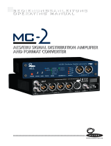
USING REDNET CONTROL
RedNet Control will reect the status of the RedNet units present in the system, presenting an
image representing each hardware unit.
The illustration above shows a RedNet A8R with signals present on all input and output channels.
The unit has a single PSU input, single network input and a locked network connection.
PSUs A & B – Each illuminates if PSU has power input and all DC outputs are present
Networks – Each illuminates if a valid connection is present.
Locked – Unit is successfully locked to the network (changes to the red cross if not locked).
Network Master – Illuminated, indicating that unit is network master.
External Clock – Green: Illuminates when external clock is selected and locked.
Amber: Illuminates when external clock is selected but not locked.
Red: Illuminates when external clock is selected but not connected.
Signal Metering
Each input and output channel has a three-segment meter. The dierent states illuminate at the
below values:
Green: –42 dBFS
Amber: –6 dBFS
Red: 0 dBFS
–SRC– : Indicates sample rate converters are switched on for the AES/EBU channel pair.

13
ID (Identication)
Clicking on the ID icon will identify the physical device being controlled by ashing its front panel
LEDs.
Tools Menu
Clicking on the Tools icon will gain access to the following system settings:
Line Level Setup – Sets the analogue line output level at 0 dBFS:
• +18dBu
• +24dBu Factory default setting
[Inputs 15 & 16 from XLR] – Tick option (RedNet A16R units only). When selected, analogue channels 15
and 16 are replaced by the AES/EBU channel pair.
Note: Option is only functional when unit is operating at quad sampling rate.
Preferred Master – On/O state.
RedNet Clock Source – Only one of the following can be selected at any time:
• Internal (RedNet is network master but running from internal clock)
• Work Clock Input - (BNC Input)
• XLR Input (DARS)
Word Clock Input Termination – Tick option On/O. (Terminates word clock input BNC with 75Ω.)
Word Clock Output – One can be selected at any time.
• Network
• Network (Base Rate)
AES/EBU Input SRC – On/O state. Applicable to channels 9 & 10 [17 & 18]. Enables Sample Rate
Converters

14
APPENDIX
Connector Pinouts
Ethernet Connector
Connector type: RJ-45 receptacle
Applies to: Ethernet (Dante)
DB-25 (AES59) Connector
Connector type: DB-25 receptacle
Applies to: Analogue I/O
Screw binding-posts use the standard UNC 4/40 thread
XLR Connectors
Connector type: XLR-3 receptacle
Applies to: AES/EBU-DARS Input
Connector type: XLR-3 plug
Applies to: AES/EBU Output
Pin Cat 6 Core
1 White + Orange
2 Orange
3 White + Green
4 Blue
5 White + Blue
6 Green
7 White + Brown
8 Brown
Pin Signal
1 Screen
2 Hot (+ve)
3 Cold (–ve)
11
8
1
8
113
25 14
Pin Signal
1 Channel 8 +
14 Channel 8 –
2 Ground
15 Channel 7 +
3 Channel 7 –
16 Ground
4 Channel 6 +
17 Channel 6 –
5 Ground
18 Channel 5 +
6 Channel 5
19 Ground
7 Channel 4 +
20 Channel 4 –
8 Ground
21 Channel 3 +
9 Channel 3 –
22 Ground
10 Channel 2 +
23 Channel 2 –
11 Ground
24 Channel 1 +
12 Channel 1 –
25 Ground
13 n/c

15
PERFORMANCE AND SPECIFICATIONS
Line Inputs
All measurements taken at +24dBu reference level, Rs = 50Ω
0 dBFS Reference Level +18 or +24dBu (switchable)
Frequency Response 20Hz – 20kHz ± 0.1dB
THD + N <-100dB (0.001%) unweighted, 20Hz – 20kHz; -1dBFS input
EIN -96dBu ‘A’-Weighted (typical)
Signal-to-Noise Ratio 120dB ‘A’-Weighted (typical)
Converter Dynamic Range 120dB ‘A’-Weighted (typical), 10Hz – 20kHz
Line Outputs
All measurements taken at +24dBu reference level, RL = 100kΩ
0 dBFS Reference Level +18 or +24dBu (switchable)
Frequency Response 20Hz – 20kHz ± 0.1dB
THD + N <-100dB (0.001%) unweighted, 20Hz – 20kHz; +23dBu input
Noise in Presence of
Signal
-94dBu ‘A’-Weighted (typical)
Dynamic Range 118 dB ‘A’-Weighted (typical)
Convertor Dynamic Range 120dB ‘A’-Weighted (typical), 10Hz – 20kHz
Crosstalk
Input to Output or Input <-100dB unweighted, 20Hz – 20kHz; +23dBu input
Output to Input or Output <-100dB unweighted, 20Hz – 20kHz; -1dBFS input
Input Sample Rate Converters
Sample Rate Range 32kHz to 216kHz
Gain Error -0.3dB
Dynamic Range > 138dB
THD+N <-130dB (0.00003%)
Latency 11 to 45 samples (network and sample rate dependent)

16
Rear Panel Connectivity
Analogue Audio
Channel Count
8 [16] channels input and output
Input and Output
2 [4] x DB-25 female connectors (AES59 / Tascam Analogue)
AES/EBU
Channel Count
2 channels input and output
Alternate Input (optional
DARS)
1 x XLR-3 female [Switchable with analogue input channels 15 and 16 at quad rates]
Alternate Output
1 x XLR-3 male [Duplicate of analogue output channels 15 and 16 at quad rates]
Word Clock
Input
1 x BNC 75Ω port (switchable termination)
Output
1 x BNC 75Ω port
PSU & Network
PSU
2 x IEC Inputs with retaining clips
Network
2 x etherCON NE8FBH, also compatible with standard RJ45 connectors
(Accomodates rugged etherCON NE8MC*. Does not intermate with Cat 6 cable connector
NE8MC6-MO and NKE65* cable)
Digital Performance
Supported Sample Rates 44.1 / 48 / 88.2 / 96 / 176.4 / 192 kHz (-4% / -0.1% / +0.1% / +4.167%) at 24 bit
Clock Sources Internal or from Dante Network Master.
External Word Clock
Range
Nominal sample rate ±7.5%
Front Panel Indicators
Primary PSU (A) Green LED. Illuminates when an AC input is applied and all DC outputs are present.
Primary PSU (B) Green LED. Illuminates when an AC input is applied and all DC outputs are present.
Primary Network
Green LED. Indicates that a network connection is present on primary port when in
redundant mode. When in Switched mode, a valid network connection at either Primary or
Secondary network port will cause this LED to illuminate.
Secondary Network
Green LED. Indicates that a network connection is present on secondary port when in
redundant mode. Not used in switched mode.
Network Locked
Green LED. When unit is network slave, shows valid network lock. When unit is network
master, shows lock to internal clock.
Sample Rate Orange LED for each: 44.1 kHz, 48 kHz, x2, x4.
Pull Up/Down Orange LED. Indicates that the unit is set to operate on a Dante pull up/down domain.
Channel Signal Level
8 [16] Input and 8 [16] Output tri-state signal level LEDs: Green LED (> -42dB), Orange
LED (> -6dB) and Red (> 0dB)
AES/EBU 2 I/O signal indicator LEDs (one input, one output). Green LED illuminates >-127dBFS
Clock Source Orange LED for each: Internal, Word Clock and DARS

17
Network Modes
Redundant Allows unit to connect to two independent networks.
Switched Connects both ports to integrated network switch allowing daisy-chaining of devices.
Power
PSUs
2 x Internal, 100-240V, 50/60Hz, consumption 24 [41] W
Dimensions
Height 44.5mm / 1.75” (1RU)
Width 482.09mm/ 18.98”
Depth 352.12mm/ 12.80"
Weight
Weight
4.52 [4.78] kg

18
Focusrite RedNet Warranty and Service
All Focusrite products are built to the highest standards and should provide reliable performance
for many years, subject to reasonable care, use, transportation and storage.
Very many of the products returned under warranty are found not to exhibit any fault at all. To
avoid unnecessary inconvenience to you in terms of returning the product please contact Focusrite
support.
In the event of a Manufacturing Defect becoming evident in a product within 12 months from the date
of the original purchase Focusrite will ensure that the product is repaired or replaced free of charge.
A Manufacturing Defect is dened as a defect in the performance of the product as described and
published by Focusrite. A Manufacturing Defect does not include damage caused by post-purchase
transportation, storage or careless handling, nor damage caused by misuse.
Whilst this warranty is provided by Focusrite the warranty obligations are fullled by the distributor
responsible for the country in which you purchased the product.
In the event that you need to contact the distributor regarding a warranty issue, or an out-of-warranty
chargeable repair, please visit: www.focusrite.com/distributors
The distributor will then advise you of the appropriate procedure for resolving the warranty issue.
In every case it will be necessary to provide a copy of the original invoice or store receipt to the
distributor. In the event that you are unable to provide proof of purchase directly then you should
contact the reseller from whom you purchased the product and attempt to obtain proof of purchase
from them.
Please do note that if you purchase a Focusrite product outside your country of residence or business
you will not be entitled to ask your local Focusrite distributor to honour this limited warranty,
although you may request an out-of-warranty chargeable repair.
This limited warranty is oered solely to products purchased from an Authorised Focusrite Reseller
(dened as a reseller which has purchased the product directly from Focusrite Audio Engineering
Limited in the UK, or one of its Authorised Distributors outside the UK). This Warranty is in addition
to your statutory rights in the country of purchase.
Registering Your Product
For access to Dante Virtual Soundcard, please register your product at: www.focusrite.com/register
Customer Support and Unit Servicing
You can contact our dedicated RedNet Customer Support team free of charge:
Email: [email protected]
Phone (UK): +44 (0)1494 462246
Phone (USA): +1 (310) 322-5500
Troubleshooting
If you are experiencing problems with your RedNet A8R/A16R, we recommend that in the rst in-
stance, you visit our Support Answerbase at: www.focusrite.com/answerbase
/