John Lewis JLBIHD904 User manual
- Category
- Cooker hoods
- Type
- User manual
This manual is also suitable for

JLBIHD603 - JLBIHD904
built-in cooker hood
Instruction manual

2
Important Safety Information
It is most important that this instruction manual should be retained with the appliance for future
reference. Should the appliance be sold or transferred to another owner, or should you move house and
leave the appliance, always ensure that the book is supplied with the appliance in order that the new
owner can get to know the functioning of the appliance and the relevant warnings. These warnings ha
ve been pr ovided in the inter est of saf ety . You MUST read them carefully before use or installa-
tion by a qualified person. If you are unsure of the meanings of these warnings contact the John Lewis
branch from which you purchased the appliance.
Installation
• Any installation work must be undertaken by a qualified and
competent person to the relevant National Standards.
• This hood must be installed in accordance with the instal-
lation instructions and all measurements must be adhered
to.
• If the cooker hood is installed for use above a gas appliance
then the provision for ventilation must be in accordance
with the Gas Safety Codes of Practice BS.6172, BS.5440
and BS.6891 (Natural Gas) and BS.5482 (LP Gas) 1994,
the Gas Safety (Installation & Use) Regulations, the Building
Regulations issued by the Department of the Environment,
the Building standards (Scotland) (Consolidated) Regula-
tions issued by the Scottish Development Department.
• The fan motor of this cooker hood incorporates a cut-out
device which will operate if the cooker hood is installed
below the minimum height recommended under section
‘Clearance Height’, or if the motor becomes overheated.
If the cut-out device is activated, switch off the fan motor
and allow the cooker hood to cool. The cut-out device will
reset itself when the fan motor has cooled significantly.
• It is dangerous to alter the specifications or modify this
product in any way.
• When installed between adjoining wall cabinets the wall
cabinets must not overhang the hob.
• If the room where the hood is to be used contains a fuel
burning appliance such as a central heating boiler then its
flue must be of the room sealed or balanced flue type.
• If other types of flue or appliances are fitted ensure that
there is an adequate supply of air to the room.
• The ducting system for this appliance must not be con-
nected to any existing ventilation system which is being
used for any other purpose.
• Do not install above a cooker with a high level grill.
Child Safety
• This appliance is designed to be operated by adults. Chil-
dren should not be allowed to tamper with the controls
or play with the appliance.
Use
• This product is for domestic use only.
• Never leave frying pans unattended during use as over-
heated fats and oils might catch fire.
• Never do flambé cooking under this cooker hood.
• Do not leave naked flames under the hood.
• This cooker hood is designed to extract unpleasant odours
from the kitchen, it will not extract steam.
Maintenance and Cleaning
• This appliance can be a hazard if the synthetic paper and
charcoal filters are not replaced as recommended.
Service
• Under no circumstances should you attempt to repair the
appliance yourself. Repairs carried out by inexperienced
persons may cause injury or more serious malfunction.
Refer to your local Service Force Centre. Always insist
on genuine spare parts.
Environmental Information
• After installation please dispose of the packaging with due
regard to safety and the environment.
• The symbol
on the product or on its packaging
indicates that this product should not be treated
as normal household waste. Instead it shall be handed over
to an approved collection facility for the recycling
of electrical and electronic equipment. By ensuring
this product is disposed of correctly, you will help prevent
potential negative consequences for the environment and
human health, which could otherwise be caused by
inappropriate waste handling of this product. For more
detailed information about recycling of this product, please
contact your local city office, your household waste
disposal service or the shop where you purchased the
product.

3
For the User
Important Safety Information 2
Description of the Appliance 4
Using the cooker hood 10
Cooker Hood Controls 10
To Operate 10
Recirculation 10
Extraction 10
Maintenance and Cleaning 11
External Cleaning 11
Metal Grease Filters 11
Charcoal Filters 12
To Remove/Replace Charcoal Filter 12
Changing the Light Bulb 12
Something Not Working 13
Repairs and After Sales Service 13
Contents
For the Installer
Electrical Connections 9
Electrical Requirements 9
Electrical Connection 9
Installing the Cooker Hood 5
Installation Requirements 5
Unpacking 5
Fitting the Wall Brackets 6
Fitting the Canopy Hood 6
Extraction 7
Recirculation 7
Fitting the Chimney Stack 8
Guide to use the Instruction Manual
The following symbols will be found in the text to guide
you through the instruction book
Step by step instructions
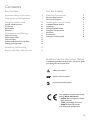
This appliance complies with the fol-
lowings E.E.C. Directives:
- 89/336 (Electromagnetic Compat-
ibility Directive)
- 73/23 (Low Voltage Directive)
- 93/68 (General Directives)
and subsequent modifications
Safety instructions
Environmental Information

4
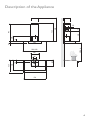
650 min.
520
420
46
8
598 / 898
530
108
259
150
740
740
945
90
135
433
260
300
Description of the Appliance

5
Please ensure that when the appliance is installed
it is easily accessible to an engineer in the event
of a breakdown.
All installations must comply with the local
authorities requirements for the discharge of
exhaust air.
Incorrect installation may affect the safety of
this cooker hood.
Installation Requirements
Before installation check the wall to which
the cooker hood is to be fitted for electric
cables, water pipes or gas.
The chimney hood must be installed accord-
ing to the instructions suppliers below and
by qualified and competent personnel to the
relevant National Standards.
This cooker hood is designed to be fixed to any vertical
surface over a cooking area, and can be used in the extrac-
tion (ducted to the outside) or recirculation mode.
The installation work must be undertaken by a qualified
and competent person.
The manufacturer disclaims any responsibility for dam-
age due to incorrect installation of the cooker hood or
if the hood is not installed in compliance with relevant
regulations controlling this type of installation.
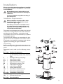
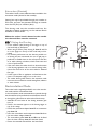
Unpacking
Before unpacking the cooker hood position the carton
with the arrows pointing upwards as illustrated on the
carton.
The cooker hood is made up of the following compo-
nents:
Ref Qty Product Components
1 1 Canopy complete with: Controls, Light-
ing, Fan Assembly, Grease Filter, Charcoal
Filter.
2 1 Telescopic Chimney comprising:
2.1 1 Upper Chimney Stack
2.2 1 Lower Chimney Stack
8a 1 Right-Hand Recirculation grille
8b 1 Left-Hand Recirculation grille
9 1 ø150-120 Ducting Spigot
10 1 ø120-125 Ducting flange
14 1 Ducting Extension Pipe
14.1 2 Recirculation Outlet Extentions
15 1 Recirculation Outlet Adapter
Ref Qty Installation Components
7.2.1 2 Upper chimney wall fixing brackets
12c 6 Chimney fixing screws
Ref Qty Documentation
1 Instruction booklet
2.1
2.2
2
12c
7.2.1
1
8a
9
10
8b
14
14.1
15
Installation

6
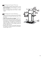
Fitting the Wall Brackets
• Draw a vertical line on the supporting wall up to the
ceiling, or as high as practical, at the centre of the area
in which the hood will be installed.
• Draw a horizontal line at 650 mm above the hob.
• Place bracket item 7.2.1 on the wall as shown about 1-2
mm from the ceiling or upper limit aligning the centre
(notch) with the vertical reference line.
• Mark the wall at the centres of the holes in the brack-
et.
• Place bracket item 7.2.1 on the wall as shown at X mm
below the first bracket (X = height of the upper chim-
ney section supplied), aligning the centre (notch) with the
vertical line.
• Mark the wall at the centres of the holes in the brack-
et.
• Draw a horizontal line through the vertical at 306mm
above the hob and mark two hole centres at 116mm
either side of the vetical line.
• Drill ø 8 mm holes at all the centre points marked.
• Insert the wall plugs (not supplied) in the holes.
• Fix the brackets using the screws (not supplied).
• Insert two screws into the two holes 116mm either side
of the vertical line and tighten leaving a space between
the underside of the screwhead and the wall of 5-6mm.
Note: If the hood is to be installed onto a hollow
construction or plaster or partition board wall
then special fixing screws will be required (not
supplied).
Fitting the Canopy Hood
• Before starting to fix the hood body, tighten the two
screws item Vr located on the top of the hood body.
• Hook the hood body onto the two screws item 12a.
• Fully tighten the screws item 12a.
• Using a screw driver and spirit level, adjust the screws
item Vr until the hood body is level.
11
12a
306
X
116
1÷2
116
650 min.
7.2.1
12a
Vr
Installing the Cooker Hood

7
Extraction (Ducted)
The cooker hood is more effective when installed in the
extraction mode (ducted to the outside).
Venting kits may be purchased through your retailer or
DIY store, and must be evacuated through an outside
vent of ø125 (5ins) or ø150mm (6ins).
The ducting used must be manufactured from fire
retardent material conforming to the relevant British
Standard or DIN 4102-B1.
When the cooker hood is ducted to the outside
the charcoal filter must be removed.
Fitting the Ducting
• Fit the ø150mm (6ins) ducting to the spigot on top of
the hood body as illustrated.
• When using ø125mm (5ins) ducting fit item 9 and 10
on to the spigot on the top of the hood body as illus-
trated.
• For the best performance use the shortest possible run
of ducting and we recommend the use of rigid pipe in
preference to flexible hose as this will improve the flow
of air while reducing turbulence, which causes noise and
a loss of performance.
• If the room where the cooker hood is to be used contains
a fuel burning appliance such as a central heating boiler,
then its flue must be be of the room sealed or balanced
flue type.
• If other types of flue or appliances are fitted ensure that
there is an adequate supply of air to the room.
• The cooker ducting when fitted in the extraction mode
must never be connected to central heating flues, radiators
or water heaters.
Recirculation Mode
The cooker hood is supplied specified for use in the recircula-
tion mode, with the charcoal filter fitted.
In the recirculation mode contaminated air is passed through
the charcoal filter to be purified and recirculated into the kitch-
en through the grille outlets on either side of the chimney.
• Assemble the two halves of the ducting extension pipe
item 14.
• Push-fit the extension pipe on to the ducting spigot on
top of the canopy.
• Push-fit the recirculation adapter item 15 on to extension
pipe item 14.
• Insert the recirculation outlet extensions item 14.4 into
the recirculation adapter item 15.
• The recircualtion grilles item 8a and 8b must be fitted
after the lower chimney item 2.2 has been fitted.
• Ensure the activated charcoal filter has been fitted.
9
ø 150
ø 125
10
14
14.115
8a
8b

8
Fitting the Upper Chimney
• Expand the sides of the upper chimney stack item 2.1 and
place the chimney over the two brackets 7.2.1 ensuring
they are well seated.
• Secure the chimney stack to the brackets 7.2.1 using
the four self tapping screws item 12c (2.9 x 9.5mm)
supplied.
Fitting the Lower Chimney
• Expand the of the lower chimney stack item 2.2 and place
the chimney over the upper chimney stack item 2.1 and
the canopy .
• Secure the chimney stack to the canopy using the two
screws item 12c (2.9 x 9.5mm) supplied..
• After the chimney has been secured into position, insert
the two plastic recirculation grilles item 8a (right-hand)
and 8b (left-hand) in the apertures on each side of the
chimney. The grilles are marked with two arrows and
should be fitted with one arrow pointing upwards and
the other toward the front.
• When the hood is used in the recirculation mode ensure
that the grilles are properly secured to the recirculation
extension spigot item 14.1.
12c
8a
2.1
2.2
2
8b
7.2.1
12c

9
Electrical Connections
Electrical Requirements
Any permanent electrical installation must comply with
the latest I.E.E. Regulations and local Electricity Board
regulations. For your own safety this should be under-
taken by a qualified electrician e.g. your local Electricity
Board, or a contractor who is on the roll of the National
Inspection Council for Electrical Installation Contracting
(NICEIC).
Electrical Connection
Before connecting to the mains supply ensure that the
mains voltage corresponds to the voltage on the rating
plate inside the cooker hood.
Remove the grease filters (see paragraph Maintenance)
being sure that the connector of the feeding cable is
correctly inserted in the socket placed on the side of
the fan.
This appliance is fitted with a 3 core mains cable and
must be permanently connected to the electricity supply
via a double-pole switch having 3mm minimum contact
gap on each pole. A Switched Fuse Connection Unit to
BS1363 Part 4, fitted with a 3 Amp fuse, is a recom-
mended mains supply connection accessory to ensure
compliance with the Safety Requirements applicable to
fixed wiring instructions.
This appliance conforms to BS 800: 1988 and EEC Di-
rective No. 78 308 regarding suppression of radio and
television interference.
DOUBLE INSULATED DO NOT EARTH

10
Using the cooker hood
The cooker hood is designed to extract unpleasant
odours from the kitchen, it will not extract steam.
The appliance can be installed to recirculate or extract
contaminated air.
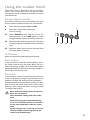
Cooker Hood Controls
The cooker hood functions are controlled by four push
button switches located centrally in the control fascia.
L Turns the worktop lighting On and Off
S Mains light - illumination indicates fan
motor is running
V1 Motor ON/OFF switch. Depress to turn the
extractor motor on at a LOW speed, to ensure
that light cooking vapours are silently extracted.
V2 Medium speed, suitable for general use. This speed
provides an optimum treated air flow to noise level
ratio.
V3 Maximum speed, used to extract intensive levels
of cooking vapour emissions.
To Operate
Select the required fan speed and light if required.
Recirculation
In the recirculation mode the contaminated air enters
the cooker hood through the grease filters. The air is
cleaned by passing through the charcoal filters before
being passed back into the kitchen through the grilles in
either side of the chimney stack.
Extraction
In the extraction mode the contaminated air enters the
cooker hood passing through the grease filters and is
passed out through the ducting into the atmosphere.
To obtain the best performance when cooking it is advis-
able to switch the cooker hood on for a few minutes
before you start cooking and leave it running for about
15 minutes after finishing.
When used in the ducting mode the charcoal
filters are not required.
Never do flambé cooking under this cooker
hood.
Never leave frying pans unattended during
use, as over-heated fats and oils can catch fire.
Do not leave naked flames under the cooker
hood.
Ensure heating areas on your hob are covered
with pots and pans when using the hob and
cooker hood simultaneously.
L
V1 V2 V3
S

11
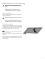
Before carrying out any maintenance or lean-
ing isolate the cooker hood from the mains
supply.
The cooker hood must be kept clean, as a
build up of grease or fat can be a fire hazard.
External cleaning
Wipe the cooker hood frequently with warm soapy water
using a mild detergent.
Never use scouring pads or abrasive cleaners.
Never use excessive amounts of water when
cleaning particularly around the control panel.
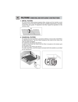
Metal Grease Filters
The grease filters absorb grease and dust during cooking
to help keep the cooker hood clean inside, and should be
cleaned approximately once every month or more often
if the hood is used for more than 3 hours a day.
Remove the metal grease filters
one at a time by:
Releasing the catches on the filters, the filters can be
removed.
The metal grease filters should be washed, by hand, in mild
soapy water or in a dishwasher. Allow to dry completely
before replacing.
Maintenance and Cleaning

12
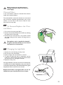
Before carrying out any maintenance or
cleaning isolate the cooker hood from the
mains supply.
Charcoal Filters
In the recirculation mode the charcoal filters absorb
smells and unwanted odours.
The charcoal filters cannot be cleaned, we recommend
they should be replaced approximately every three
months or more often if the hood is used for more
than three hours per day.
To Remove/Replace the Char-
coal Filters
1. First remove the metal grease filters.
2. Remove the saturated activated charcoal filter by releasing
the fixing hooks as illustrated.
3. Position the new charcoal filter in the position marked
and while holding the filter replace the fixing hooks as
illustrated
This appliance can be a possible fire hazard if
the grease and charcoal filters are not cleaned
and replaced as recommended.
Changing the Light Bulb
1. Remove the screw fastening the lamp cover.
2. Pull the lamp cover downwards.
3. Rotate the light bulb anti-clockwise to unscrew.
4. To replace the light bulb insert a replacement into the
holder then rotate the bulb clockwise into position. Ensure
you take care not to overtighten the bulb.
5. Replace the lamp cover.
If the light bulb fails to function check that the bulb is fully
screwed into the holder. If bulb failure has occurred then
it should be replaced with a 220-240 Volt 40W clear globe
shaped bulb with a small E14 screw thread.
Replacement filters and light bulbs can be ob-
tained from your local Service Force Centre.

13
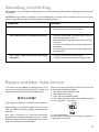
Something not Working
Repairs and After Sales Service
If the appliance is not working correctly, please carry out the following checks, before contacting your local Service
Force agent.
IMPORTANT: If you call out an engineer to a fault listed below, or to repair a fault caused by incorrect use or instal-
lation, a charge will be made even if the appliance is under guarantee.
Symptom
The cooker hood will not start
The cooker hood is not working effectively
The cooker hood has switched off during
operation
Solution
• Check the hood is connected to the electricity supply.
• Make sure the switch is in the ‘ON’ position.
• Check that the fan speed is set high enough for the task
• Ensure the grease filter is clean.
• Ensure the kitchen is adequately vented to allow the entry
of fresh air.
• If set up for recirculation, check that the charcoal filter is
still effective.
• If set up for extraction, check that the ducting and outlets
are not blocked.
• The safety cut-out device has been tripped.
• Tum off the hob and then wait for the device to reset.
In the event of your appliance requiring service, or if
you wish to purchase spare parts, please contact our
extended warranty administrators by telephoning:
0870 01 07887
They will give you details for your local Service Force Centre.
Before calling out an engineer, please ensure you have
read the details under the heading “Something Not
Working”.
Your oven is covered by a 3 year parts and labour
guarantee (see separate details given at point of sale).
Please retain your purchase receipt safely for the service
engineer to verify the purchase details.
When you contact the Service Force Centre you will
need to give the following details:
1. Your name, address and post code
2. Your telephone number
3. Clear and concise details of fault
4. The model and serial number of the appliance (found
on the rating plate - see picture)
5. The purchase date.
Please note that a valid purchase receipt is required for
in-guarantee service calls.


436002887_02 - 060227
John Lewis Partnership
171 Victoria Street
London SW1E 5NN
www.johnlewis.com
0306
-
 1
1
-
 2
2
-
 3
3
-
 4
4
-
 5
5
-
 6
6
-
 7
7
-
 8
8
-
 9
9
-
 10
10
-
 11
11
-
 12
12
-
 13
13
-
 14
14
-
 15
15
-
 16
16


John Lewis JLBIHD904 User manual
- Category
- Cooker hoods
- Type
- User manual
- This manual is also suitable for
Ask a question and I''ll find the answer in the document
Finding information in a document is now easier with AI
Related papers
-
John Lewis JLBIHD105 User manual
-
-
-
-
-
-
-
-
-
Other documents
-
 Futuro Futuro WL36BOSTON Filters
-
Rangemaster LEIHDC60BB User manual
-
Zanussi ZHC960A/GB User manual
-
-
Electrolux EFC70710 User manual
-
-
-
-
-
