Page is loading ...


14
ENGLISH
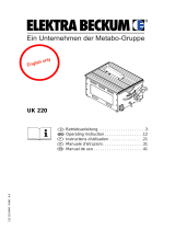
1. Getting To Know Your Saw
3
1
4
5
6
7
8
9
10
11
1214 13
Rear:
16
17
19
21
20
2
18
Right/hand side:
15
1 Riving knife
2 Push stick / feeding aid
3 Mitre fence
4 Blade guard
5 Rip fence
6 Table extension
7 Lock lever for table side exten-
sion
8 ON/OFF switch
9 Reset button
to reset a tripped motor protection
10 Handwheel for depth of cut
setting
11 Ratchet lock lever to lock saw
blade tilt
12 Release lever for bevel tilt stop
13 Push stick holder
14 Mitre fence holder
15 Rip fence holder
16 Saw blade holder with cable
storage and and tool holding
fixture
17 Dust spout
18 Retaining nut
Tools
19 Box end wrench
20 Open end wrench
21 Allen key
XA0049E3.fm Original operating instructions ENGLISH

15
ENGLISH
1. Getting To Know Your Saw......14
2. Please Read First!.....................15
3. Safety.........................................15
3.1 Specified conditions of use .........15
3.2 General safety instructions .........15
3.3 Symbols on the machine ............16
3.4 Safety devices ............................17
4. Special Product Features.........17
5. Transportation ..........................17
6. Operating Elements..................17
7. Initial Operation ........................18
7.1 Assembly ....................................18
7.2 Installation...................................19
7.3 Mains connection........................19
8. Operation...................................20
8.1 Dust collector ..............................20
8.2 Setting the depth of cut...............20
8.3 Setting the saw blade tilt.............20
8.4 Sawing........................................20
9. Care And Maintenance.............21
9.1 Saw blade change ......................21
9.2 Adjusting the scale's pointer .......22
9.3 Adjusting the scale's pointer .......22
9.4 Adjusting the mitre fence stops...22
9.5 Adjusting the blade tilt stop.........22
9.6 Saw Cleaning..............................22
9.7 Saw storage................................22
9.8 Maintenance ...............................22
10. Tips and Tricks .........................22
11. Available Accessories......... 23/49
12. Repairs.......................................23
13. Environmental Protection ........23
14. Trouble Shooting ......................23
15. Technical specifications .......... 23
These instructions have been written in
a way which facilitates learning of how to
safely operate your saw. Here is a guide
on how you should read these instruc
-
tions:
− Read instructions before use. Pay
special attention to the safety infor-
mation.
− These instructions are intended for
persons having a basic technical
knowledge of the operation of
machines such as the one
described herein. If you have no
experience whatsoever, we strongly
recommend to seek the advise of an
experienced person.
− Keep all documents supplied with
this machine for future reference.
Retain proof of purchase in case of
warranty claims.
− If you lend or sell this machine be
sure to have these instructions go
with it.
− The equipment manufacturer is not
liable for any damage resulting from
neglect of these operating instruc
-
tions.
Information in these instructions is
denoted as under:
Danger!
Risk of personal injury or
environmental damage.
Risk of electric shock!
Risk of personal injury
by electric shock.
Drawing-in/trapping haz-
ard!
Risk of personal injury
by body parts or clothing
being drawn into the
rotating saw blade.
Caution!
Risk of material damage.
Note:
Additional information.
− Numbers in illustrations (1, 2, 3, ...)
− denote component parts;
− are consecutively numbered;
− relate to the corresponding
number(s) in brackets (1), (2), (3)
... in the neighbouring text.
− Instructions to be carried out in a
certain sequence are numbered.
− Instructions which can be carried
out in any sequence are indicated
by a bullet.
− Listings are indicated by an En
Dash.
3.1 Specified conditions of
use
This machine is intended for ripping and
crosscutting grown timber, faced boards,
chip board and wood-core plywood
sheets, and similar wood-derived materi
-
als.
Metals can only be cut with the following
restrictions:
− With suitable saw blade only
(see “Available Accessories”)
− Non-ferrous metals only
(no hard or hardened metals)
Do not cut round stock without suitable
jigs or fixtures. The rotating saw blade
could turn the workpiece.
When sawing thin stock layed on edge,
a suitable guide must be used for firm
support.
Use of wobble saw blades is not permit-
ted on this machine.
Any other use is considered to be not as
specified and not allowed. The manufac-
turer is not liable for any damage caused
by unspecified use.
Modification of the machine or use of
parts not approved by the equipment
manufacturer can cause unforeseeable
damage!
3.2 General safety instruc-
tions
• When using this tool observe the fol-
lowing safety instructions, to
exclude the risk of personal injury or
material damage.
• Please also observe the special
safety instructions in the respective
chapters.
• Where applicable, follow the legal
directives or regulations for the pre-
vention of accidents pertaining to
the use of circular saws.
A
General hazards!
• Keep your work area tidy – a messy
work area invites accidents.
• Be alert. Know what you are doing.
Set out to work with reason. Do not
operate tool while under the influence
of drugs, alcohol or medication.
• Consider environmental conditions:
keep work area well lighted.
• Prevent adverse body positions.
Ensure firm footing and keep your
balance at all times.
• Use suitable workpiece supports
when cutting long stock.
• Do not operate the tool near inflam-
mable liquids or gases.
• The saw shall only be started and
operated by persons familiar with
circular saws and who are at any
time aware of the dangers associ
-
ated with the operation of such tool.
Persons under 18 years of age shall
use this tool only in the course of
their vocational training, under the
supervision of an instructor.
• Keep bystanders, particularly chil-
dren, out of the danger zone. Do not
permit other persons to touch the
tool or power cable while it is run
-
ning.
• Do not overload tool – use it only
within the performance range it was
designed for (see “Technical Speci
-
fications”).
Table of Contents
2. Please Read First!
3. Safety

16
ENGLISH
B
Danger! Risk of electric shock!
• Do not expose tool to rain.
Do not operate tool in damp or wet
environment.
Prevent body contact with earthed
objects such as radiators, pipes,
cooking stoves, refrigerators when
operating this tool.
• Do not use the power cable for pur-
poses it is not intended for.
A
Risk of personal injury and
crushing by moving parts!
• Do not operate the tool without
installed guards.
• Always keep sufficient distance to
the saw blade. Use suitable feeding
aids, if necessary. Keep sufficient
distance to driven components
when operating the electric tool.
• Wait for the saw blade to come to a
complete stop before removing cut
-
offs, scrap, etc. from the work area.
• Do not attempt to stop the saw
blade by pushing the workpiece
against its side.
• Ensure the tool is disconnected from
power before servicing.
• Ensure that when switching on (e.g.
after servicing) no tools or loose
parts are left on or in the tool.
• Turn power off if the tool is not used.
A
Cutting hazard, even with the
cutting tool at standstill!
• Wear gloves when changing cutting
tools.
• Store saw blade in such manner that
nobody will get hurt.
A
Risk of kickback (workpiece is
caught by the saw blade and thrown
against the operator):
• Always work with a properly set riv-
ing knife.
• The riving knife and the saw blade
used must match: the riving knife
should be thinner than the kerf, but
thicker than the saw blade body.
• Do not jam workpieces.
• Make sure the saw blade is suitable
for the workpiece material.
• Cut thin or thin-walled workpieces
only with fine-toothed saw blades.
• Always use sharp saw blades.
• If in doubt, check workpiece for
inclusion of foreign matter (e.g. nails
or screws).
• Cut only stock of dimensions that
allow for safe and secure holding
while cutting.
• Never cut several workpieces at the
same time – and also no bundles
containing several individual pieces.
Risk of personal injury if individual
pieces are caught by the saw blade
uncontrolled.
• Remove small cutoffs, scrap, etc.
from the work area – when doing so
the saw blade must be at a com
-
plete standstill.
c
Drawing-in/trapping hazard!
• Ensure that no parts of the body or
clothing can be caught and drawn in
by rotating components (no neck-
ties, no gloves, no loose-fitting
clothes; contain long hair with hair-
net).
• Never attempt to cut any workpieces
which contain
− ropes,
− strings,
− cords,
− cables or
− wires, or to which any of the
above are attached.
A
Hazard generated by insuffi-
cient personal protection gear!
• Wear hearing protection.
• Wear safety glasses.
• Wear dust mask.
• Wear suitable work clothes.
• When working outdoors wearing of
non-slip shoes is recommended.
A
Risk of injury by inhaled wood
dust!
• Dust of certain timber species (e.g.
beech, oak, ash) can cause cancer
when inhaled. Work only with a suit-
able dust collector attached to the
saw. The dust collector must comply
with the data stated in the technical
specifications.
• Ensure that as little as possible
wood dust will get into the environ-
ment:
− remove wood dust deposit in the
work area (do not blow away!);
− fix any leakages on the dust col-
lector;
− ensure good ventilation.
A
Hazard generated by modifica-
tion of the machine or use of parts
not tested and approved by the equip
-
ment manufacturer!
• Assemble tool in strict accordance
with these instructions.
• Use only parts approved by the
equipment manufacturer. This
applies especially for:
− saw blades (see “Technical
Specifications” for stock nos.);
− safety devices (see “Technical
Specifications” for stock nos.).
• Do not change any parts.
A
Hazard generated by tool
defects!
• Keep tool and accessories in good
repair. Observe the maintenance
instructions.
• Before every use check tool for pos-
sible damage: before operating the
tool all safety devices, protective
guards or slightly damaged parts
need to be checked for proper func
-
tion as specified. Check to see that
all moving parts work properly and
do not jam. All parts must be cor
-
rectly installed and meet all condi-
tions necessary for the proper oper-
ation of the tool.
• Damaged protection devices or
parts must be repaired or replaced
by a qualified specialist. Have dam
-
aged switches replaced by a service
centre. Do not operate tool if the
switch cannot be turned ON or OFF.
• Keep handles free of oil and grease.
A
Risk of injury by noise!
• Wear hearing protection.
• Make sure the riving knife is not
bend. A bent riving knife will push
the workpiece against the side of the
saw blade, causing noise.
A
Danger from blocking work-
pieces or workpiece parts!
If blockage occurs:
1. Switch machine OFF.
2. Unplug mains cable.
3. Wear gloves.
4. Clear the blockage using a suitable
tool.
3.3 Symbols on the machine
Information on the nameplate:
(22) Manufacturer
(23) Serial number
(24) Machine designation
(25) Motor specifications (see also
"Technical specifications")
(26) Year of make
(27) CE-mark – This machine con-
forms to the EC directives as per
Declaration of Conformity
23
24
25
26 27
29
22
28

17
ENGLISH
3.4 Safety devices
Blade guard
The blade guard (31) protects against
unintentional contact with the saw blade
and from chips flying about.
Always have blade guard installed dur-
ing operation.
Riving knife
The riving knife (30) prevents the work-
piece from being caught by the rising
teeth of the saw blade and being thrown
against the operator.
Always have the riving knife installed
during operation.
Push stick
The push stick (32) serves as an exten-
sion of the hand and protects against
accidental contact with the saw blade.
Always use the push stick if the distance
between saw blade and rip fence is less
than 120
mm.
Guide the push stick at an angle of 20°
… 30° against the saw table's surface.
When the push stick is not used, it can
be hung to the holder provided at the
base's side.
Replace push stick if damaged.
− Precision adjustable bevel tilt from -
1.5 ° to 46.5°.
− Simple release of bevel tilt stop from
0° to -1.5° and 45° to 46.5°.
− Steplessly adjustable depth of cut 0
– 77 mm.
− All operating elements are located
at the machine's front.
− An electronic motor protection shuts
the motor off when it is locked (e.g.
by a blocked saw blade).
− Electronic softstart for extended
motor life.
− An undervoltage relay prevents the
machine from starting up when
power is restored after a power fail
-
ure.
− Compact design for quick and easy
transportation.
− Mitre fence and rip fence are stand-
ard delivery.
− Saw blade and holder with cable
storage.
− Pull-out table side extension.
• Lower saw blade fully.
• Set saw blade bevel tilt to 0° and
lock with lock lever.
• Remove add-on parts (blade guard,
dust extraction).
• If possible use original carton for
shipping.
A
Crushing hazard
Use handles provided on sides
of table to carry the machine (33).
Lock pulled-out table side extension
with lock lever.
A
Caution!
Do not carry the machine at the
guards, table side extension or oper-
ating elements!
ON/OFF switch
• To stop = press upper switch button
(34).
• To start = press and hold lower
switch button
(35) for 1 - 2 seconds.
3
Note: version 10
In the event of an overload a thermal
overload protection will trip. After only a
few seconds the machine can be
restarted. To restart, first press the
Reset button
(36), then the Start button
(35).
Note: from version 11
An electronic motor protection by over-
current detection shuts the motor off
when it is locked (e.g. by a blocked saw
blade). To restart, press the Start button
(35).
Note:
In the event of a power failure an under-
voltage relay trips. This prevents the
starting of the machine when power is
restored. To restart, press the Start but
-
ton (35).
Handwheel for setting the depth of cut
The depth of cut can be adjusted by
turning the handwheel
(37).
Bevel tilt lock lever
By releasing the lock lever (38) the saw
blade can be tilted from -1.5° to 46.5°.
(28) Waste disposal symbol – the
machine can be disposed of
through the manufacturer
(29) Dimensions of permissible saw
blades
30 31
32
4. Special Product Features
5. Transportation
33
6. Operating Elements
35
34
36
37

18
ENGLISH
To keep the set bevel tilt from changing
during cutting, it must be locked again by
the lock lever
(38).
Release lever for bevel tilt stop
The blade tilt setting has end stops at 0°
and 45°. For special bevel cuts (under-
cutting) the bevel angle can be
increased by 1.5° in both directions.
• Pull release lever (39) out and turn
into vertical position:
the blade bevel can now be set from
-1.5° to 46.5°.
• Set release lever (39) horizontal and
let engage in housing:
blade bevel is now adjustable from
0° to 45°.
Rip fence (for ripping):
For use as rip fence the long fence
extrusion (40) must be installed. It is
mounted on the guide extrusion at the
front of the saw table.
− For ripping the fence extrusion (40)
must be parallel with the saw blade
and locked in position by lock lever
(41).
− Wing nuts (42) for attaching the
fence extrusion. After loosening the
two wing nuts
(42), the fence extru-
sion can be removed and shifted:
Small edge:
− for cutting thin stock;
− when the saw blade is tilted.
Wide edge:
− for cutting thick stock (max. 77
mm).
3
Note:
To avoid stock jamming when
cutting along the rip fence:
slide rip fence all the way to the right
table edge and then back to the required
cutting width.
Mitre fence
The mitre fence (44) is inserted into the
table slot from the table’s front edge.
For mitre cuts the mitre fence turns to
60° in both directions.
For 45° and 90° miters positive stops are
provided.
To set a mitre angle: loosen locking han-
dle (43) by turning it counter-clockwise.
A
Risk of injury!
When cutting with the mitre
fence the handle must be firmly tight-
ened.
The auxiliary fence extrusion can be
taken off and reversed after loosening
knurled nut
(45).
Table side extension
The table side extension extents the
supporting surface, providing safe sup
-
port for larger workpieces.
• For table side extension adjustment
the lock lever (46) must be loos-
ened.
A
Risk of injury!
When cutting the handle must
always be firmly tightened.
Scale reading when using the rip
fence
On which scale the cutting width is read
depends on how the fence extrusion is
installed on the rip fence:
− Wide edge =
scale with black numerals on
white background.
− Small edge =
scale with white numerals on
black background.
For small cutting widths the table side
extension is not extended. The cuttings
width is read on the respective right-
hand scale at the rip fence's pointer:
− Wide edge: cutting width from 0 to
39 cm.
− Small edge: cutting width from 0 to
33 cm.
If larger stock is to be cut the table side
extension needs to be extended.
1. Move rip fence to the end position of
the respective right-hand scale.
2. Pull out table side extension and set
to desired cutting width. The cut
-
tings width is read on the respective
left-hand scale at the scale's pointer.
7.1 Assembly
Installing the crank for depth of cut
adjustment
• Attach crank (47) with Phillips screw
(48) to the handwheel.
38
39
40
41
42
43
4445
7. Initial Operation
46
47
48

19
ENGLISH
Adjusting the riving knife
3
Note:
The riving knife has been cor-
rectly set at the factory. Readjustment
prior to initial operation is only required
should the riving knife have become mis-
adjusted in transit.
1. Raise saw blade fully.
2. Checking the riving knife:
− Distance between the saw
blade's outer edge and the riving
knife needs to be 3 – 5 mm.
− The riving knife must be in align-
ment with the saw blade.
A
Danger!
The riving knife is one of the
safety devices and must be correctly
installed for safe operation.
Only if realignment of the riving knife is
necessary:
3. Loosen table insert (49) and remove
from table.
Setting the distance to the saw blade:
4. Loosen hexagon socket head cap
screw
(50) (to do so, turn hexagon
socket head cap screw counter-
clockwise!)
5. Pull riving knife (51) fully up against
the stop and align: the gap between
saw blade and riving knife must be 3
to 5
mm.
6. Tighten hexagon socket head cap
screw
(50) (to do so, turn hexagon
socket head cap screw clockwise!)
Lateral alignment:
riving knife and saw blade (52) must be
in true alignment.
7. Loosen hexagon nut (53) and adjust
vertical alignment with machine
screw (54).
8. Lock machine screw with (53).
9. Loosen both hexagon socket screws
(55).
10. Align riving knife flush with the saw
blade.
11. Tighten both hexagon socket
screws (55).
12. Reinstall table insert.
Blade guard installation
1. Raise saw blade fully.
2. Install blade guard (57) on riving
knife (56).
7.2 Installation
There are two ways to ensure a firm
stand of the machine:
− mounted on floor stand
(accessory);
− mounted on sturdy table or bench.
7.3 Mains connection
B
Danger! High voltage
• Operate this machine in dry sur-
roundings only.
• Operate machine only on a power
source meeting the following
requirements (see also “Techni
-
cal Specifications”):
− outlets properly installed,
earthed, and tested.
− mains voltage and system fre-
quency conform to the voltage
and frequency shown on the
machine´s rating label;
− fuse protection by a residual
current operated device (RCD)
of 30
mA sensitivity;
− System impedance Z
max
at the
interconnection point (house
service connection) 0.35 Ohm
maximum.
3
Note:
Check with your local Electricity
Board or electrician if in doubt whether
your house service connection meets
these requirements.
• Position power supply cable so it
does not interfere with the work
and is not damaged.
• Protect power supply cable from
heat, aggressive liquids and
sharp edges.
• Use only rubber-jacketed exten-
sion cables with sufficient lead
cross-section (see “Technical
Specifications”).
• Do not pull on power supply
cable to unplug.
49
50
51
52
53
54
55
56 57

20
ENGLISH
A
Risk of injury!
This saw may only be operated
by one person at a time. Other per-
sons shall stay only at a distance to
the saw for the purpose of feeding or
removing stock.
Before starting work, check to see
that the following are in proper work-
ing order:
− power cable and plug;
− ON/OFF switch
− riving knife
− blade guard
− feeding aids (push stick, push
block and handle).
Use personal protection gear:
− dust respirator;
− hearing protection;
− safety goggles.
Assume proper operating position:
− at the front of the saw;
− in front of the saw;
− to the left of the line of cut;
− when working with two persons,
the other person must remain at
an adequate distance to the saw.
If the type of work requires, use the
following:
− suitable workpiece supports – if
otherwise workpiece would fall
off the table after cutting;
− dust collector.
Avoid typical operator mistakes:
− Do not attempt to stop the saw
blade by pushing the workpiece
against its side. Risk of kickback.
− Always hold the workpiece down
on the table and do not jam it.
Risk of kickback.
− Never cut several workpieces at
the same time – and also no bun-
dles containing several individual
pieces. Risk of personal injury if
individual pieces are caught by
the saw blade uncontrolled.
c
Drawing-in/trapping hazard!
Never cut stock to which
ropes, cords, strings, cables or wires
are attached or which contain such
materials.
8.1 Dust collector
A
Danger!
Dust of certain timber species
(e.g. beech, oak, ash) can cause can-
cer when inhaled. Use suitable dust
collector when working in enclosed
spaces. The dust collector must meet
the following requirements:
− hoses to fit outer diameter of dust
extraction ports (blade guard 38
mm; chip case 58 mm);
− air flow volume ≥ 460 m
3
/h;
− vacuum at dust extraction port of
saw ≥ 530 Pa;
− air speed at dust extraction port
of saw ≥ 20 m/ s.
The dust extraction ports are located at
the chip case assembly and at the saw
blade guard.
Observe the dust collector's operating
instructions as well!
Operation without a dust collector is only
possible:
− outdoors;
− for short-term operation
(up to a maximum of 30 minutes);
− with dust respirator.
A
Danger!
By the revolving motion of the
saw blade saw dust is blown from the
chip case.
A
Caution!
The dust extraction port must
not be blocked by objects.
8.2 Setting the depth of cut
A
Danger!
Parts of the body or objects in
the setting range can be caught by
the running saw blade! Set depth of
cut only with saw blade at standstill!
The saw blade's cutting height needs to
be adapted to the workpiece height: the
blade guard shall rest with its front edge
on the workpiece.
• Adjust depth of cut by turning the
handwheel (58) as required.
3
Note:
To compensate for possible play
in the blade height setting mechanism,
always raise the blade to the desired
position.
8.3 Setting the saw blade tilt
A
Danger!
Parts of the body or objects in
the setting range can be caught by
the running saw blade! Set the depth
of cut only with the saw blade at
standstill!!
The saw blade tilt is adjustable between
-1.5 ° and 46.5°.
1. Release lock lever (59).
2. Set required saw blade tilt.
3. Lock the set bevel tilt by tightening
the lock lever (59).
8.4 Sawing
A
Danger!
Always use push stick if dis-
tance between saw blade and rip
fence is less than 120 mm.
1. Set blade tilt and lock in position.
8. Operation
58
59

21
ENGLISH
2. Set depth of cut. The blade guard
must rest with its front edge on the
workpiece.
3. Mount rip fence, if required.
4. Start saw.
5. Push workpiece in a steady motion
towards the rear and cut in a single
pass.
6. Switch machine off if no further cut-
ting is to be done immediately after-
wards.
Mitre cuts
1. The mitre fence is inserted into the
table slot from the table’s front edge.
2. Set desired angle after loosening
the mitre fence's locking handle (60)
and retighten locking handle.
3. Adjust lateral distance between aux-
iliary fence and saw blade:
• Loosen knurled nut and move auxil-
iary fence as required.
• Retighten knurled nut.
4. Hold workpiece firmly against mitre
fence.
5. Cut workpiece by pushing the mitre
fence forward.
A
Danger!
Prior to all servicing:
1. switch machine OFF;
2. wait until the saw has come to a
complete stop.
3. unplug power cable;
− Check that all safety devices are
operational again after each service.
− Replace defective parts, especially
of safety devices, only with genuine
replacement parts. Parts not tested
and approved by the equipment
manufacturer can cause unforeseen
damage.
− Repair and maintenance work other
than described in this section should
only be carried out by qualified spe
-
cialists.
A
Danger!
With a damaged table insert
there is a risk of small parts getting
stuck between table insert and saw
blade, blocking the saw blade.
Replace damaged table inserts imme
-
diately!
9.1 Saw blade change
A
Danger!
Directly after cutting the saw
blade can be very hot – burning haz-
ard! Let a hot saw blade cool down.
Do not clean the saw blade with com
-
bustible liquids.
Risk of injury, even with the blade at
standstill. Wear gloves when chang
-
ing blades.
When fitting a saw blade, observe the
direction of rotation!
1. Raise saw blade fully.
2. Remove blade guard.
3. Loosen table insert (61) and remove
from table.
4. Hold saw spindle (62) with open end
wrench.
5. Loosen arbor nut (64) with box end
wrench (left-handed thread!).
6. Remove arbor nut (64), outer blade
collar (63) and saw blade from saw
spindle.
7. Clean clamping surfaces of saw
spindle and saw blade.
A
Danger!
Do not use cleaning agents
(e.g. to remove resin residue) that
could corrode the light metal compo-
nents of the saw; the stability of the
saw would be adversely affected.
8. Put on a fresh saw blade (observe
direction of rotation!).
A
Danger!
• Use only saw blades conforming
to the technical specifications
stated and to EN
847-1 – from
unsuitable or damaged saw
blades parts can be hurled away
explosive-like by centrifugal
force.
• Do not use:
− saw blades which permissible
maximum speed is below the
rated no-load speed of the saw
spindle (see “Technical Speci
-
fications”);
− saw blades made of high
speed steel (HS or HSS);
− saw blades with visible dam-
age;
− cut-off wheel blades.
A
Danger!
− Mount saw blade using only gen-
uine parts.
− Do not use loose-fitting reducing
rings; the saw blade could work
loose.
− Saw blades have to be mounted
in such way that they do not wob-
ble or run out of balance and can-
not work loose during operation.
9. Slide on outer blade collar (63).
10. Turn on arbor nut (64) (left-handed
thread!) and tighten hand-tight only
with tool supplied.
A
Danger!
− Do not extend arbor bolt tighten-
ing wrench.
− Do not tighten arbor bolt by hit-
ting the wrench.
11. Reinstall table insert.
12. Attach blade guard.
9. Care And Maintenance
60
61
62
63
64

22
ENGLISH
9.2 Adjusting the scale's
pointer
1. Loosen pointer fixing screw and
adjust pointer
(65) to indicate the
exact Zero position.
2. Retighten pointer fixing screw.
9.3 Adjusting the scale's
pointer
1. Align rip fence with saw blade.
2. Loosen ripfence pointer fixing screw
(66).
3. Bring both pointers (rip fence and
scale) in line.
4. Retighten ripfence pointer fixing
screw
(66).
9.4 Adjusting the mitre fence
stops
The mitre fence's positive stops at both
45° positions and the 90° position are
adjustable.
1. Loosen the mitre fence locking han-
dle.
2. Set mitre fence to any positive stop
position and lock with locking handle.
3. Loosen locking nut (67) and turn
screw (68) so far out, until flip stop
(69) can be turned forward.
4. Turn screw (68) in until it just
touches the flip stop (69).
5. Tighten locking nut. The flip stop
should move without difficulty.
9.5 Adjusting the blade tilt stop
1. Set release lever (70) horizontal and
let engage (0° bis 45°).
2. Release lock lever (72) and set saw
blade tilt to 0°/45°.
3. Lock set bevel tilt by tightening lock
lever (72).
4. Check blade bevel angle:
− 0°square with the saw table
− 45°with separate mitre square.
If these angles are not exactly
matched:
5. Adjust cam plates (71) of stops until
blade tilt against the saw table at
end positions is exactly 0°= square)
and 45°respectively.
3
Note:
To adjust the bevel tilt stop for
-1.5° to 46.5°, the release lever must be
pulled out and set into vertical position.
9.6 Saw Cleaning
• Remove chips and saw dust with
vacuum cleaner or brush:
− from saw blade setting guide ele-
ments;
− from motor vent slots;
− chipcase.
Cleaning the chipcase.
If there is sawdust build-up in the chip-
case, the chipcase needs cleaning:
3
Note:
The chipcase is accessible from
below only. For cleaning, both table
insert and saw blade may be removed.
1. Loosen screw (74) only slightly.
2. Remove thumb screw (75).
3. Turn lid (73) 180°.
4. Clean chipcase.
5. Close lid (73) again, turn in thumb
screw (75). Then tighten both
screws (74), (75) hand-tight only.
9.7 Saw storage
A
Danger!
Store saw so that
− it cannot be started by unauthor-
ized persons, and
− nobody can get injured.
A
Caution!
Do not store saw unprotected
outdoors or in damp environment.
9.8 Maintenance
Before switching ON
Visual check to see if
− distance saw blade – riving knife is
5
mm maximum;
− riving knife is in line with saw blade.
Visual check of power cable and power
cable plug for damage; if necessary
have damaged parts replaced by a qual
-
ified electrician.
Monthly (if used daily)
Remove saw dust and chips with vac-
uum or brush; apply light coat of oil to
guide elements:
− threaded rod and guide rods of
blade rise and fall mechanismn:
− swivel segments.
Every 300 hours of operation
Check all screwed joints, retighten if
necessary.
• Before cutting a workpiece to size
make trial cuts on pieces of scrap.
• Always place a workpiece on the
saw table in such way that it cannot
tilt or rock (e.g. always place a
65
66
67 68
69
70
72
71
10. Tips and Tricks
75 74 73

23
ENGLISH
curved board on the table with the
convex side up).
• To simplify repetitive cut-off work
use a stock stop .
• Keep surface of table clean.
For special tasks the following accesso-
ries are available at your specialized
dealer – see back cover for illustrations:
A Floor Stand
Provides for a secure machine
stand and optimal working height;
ideal in mobile use, folds up for sav-
ing space.
B Dust Collection Attachment
Helps to protect your health and to
keep the shop clean.
C Roller/Ball Transfer Stand
For accurate guiding of long stock.
D TCT Saw Blade
250 x 2.8/1.8 x 30, 60 ATB teeth,
15° rake, 2 pinholes
For rip and cross cuts in grown tim-
ber and particle board.
E TCT Saw Blade
250 x 2.8/1.8 x 30, 80 ATB teeth,
10° rake, 2 pinholes
For rip and cross cuts in panels;
plastic, aluminium, copper extru-
sions and high-grade veneered
sheets.
F TCT Saw Blade
250 x 2.8/2.0 x 30, 80 square/trap-
ezoidal teeth, 5° negative rake, 2
pinholes
General purpose blade for plastics,
thin-walled aluminium-, copper-,
brass- and steel extrusions as well
as for panels, laminates and
veneered sheets.
A
Danger!
Repairs to electric tools must
be carried out by qualified electri
-
cians only!
Electric tools in need of repair can be
sent to the service centre of your coun
-
try. Refer to the spare parts list for the
address.
Please attach a description of the fault to
the electric tool.
The machine's packing can be 100%
recycled.
Worn out power tools and accessories
contain considerable amounts of valua
-
ble raw and rubber materials, which can
be recycled.
These instructions are printed on paper
produced with elemental chlorine-free
bleaching process.
A
Danger!
Before carrying out any fault service
or maintenance work, always:
1. switch machine OFF;
2. unplug power cable;
3. wait for saw blade to come to
standstill.
Check that all safety devices are
operational again after each fault
service.
Motor does not run
Undervoltage relay tripped by power fail-
ure:
• Restart machine.
No mains voltage
• Check cables, plug, outlet and
mains fuse.
Motor overheated, e.g. by a blunt saw
blade or chip build-up in the chip case:
• Remove cause for overheating, let
cool off for a few minutes. Then
press Reset button and restart
machine.
Stated top speed is not reached
Motor supply voltage too low:
• use a shorter extension cable or
extension cable with larger lead
cross section (≥
1.5 mm
2
).
• Have power supply checked by a
qualified electrician.
Loss of cutting performance
Saw blade blunt (possibly tempering
marks on blade body):
• Replace saw blade (see chapter
“Maintenance”).
Dust spout blocked
No dust collector connected or suction
capacity insufficient:
• connect dust collector, or
• increase suction capacity (air speed
≥
20 m/sec at chip ejection tube).
11. Available Accessories
12. Repairs
13. Environmental Protection
14. Trouble Shooting
15. Technical specifications
Voltage V 230 (1∼ 50 Hz) 110 V (1∼ 50 Hz)
Wattage power input P1
power output P
2
kW
kW
2.0 kW S6 40%
1.2 kW S6 40%
1.55 kW S6 40%
0.84 kW S6 40%
Current draw A 9.6 15.5
Fuse protection min. A 16 (time-lag) –
Protection class IP 20 IP 20
Rated no-load speed (at 230V) min
-1
3950 3900
Cutting speed (at 230V) m/s 51.7 50.1
Saw blade diameter (outer) mm 250 250
Saw blade arbor bore diameter (inner) mm 30 30
Kerf width mm 2.8 2.8
Depth of cut with saw blade vertical
at 45° saw blade tilt
mm
mm
0 ... 77
0 ... 51
0 ... 77
0 ... 51

24
ENGLISH
Dimensions length of saw table
width of saw table
height (with blade guard)
mm
mm
mm
645
755 (985)
430
645
755 (985)
430
Machine weight kg 32 32
Noise emission values according to EN 61029-1*
A-sound pressure level L
pA
A-sound power level L
WA
Uncertainty K
dB (A)
dB (A)
dB (A)
83.6
97.9
4.0
83.6
97.9
4.0
* The values stated are emission values and as such do not necessarily constitute values which are safe for the workplace.
Although there is a correlation between emission levels and environmental impact levels, whether further precautions are necessary
cannot be derived from this. Factors influencing the actually present environmental impact level in the workplace include the charac
-
teristics of the work area and other noise sources, i.e. the number of machines and other neighbouring work processes. Also, per-
missible workplace values may vary from country to country. This information is intended to assist the user in his estimate of haz-
ards and risks.

37
ITALIANO
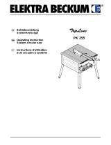
1. Panoramica della sega
3
1
4
5
6
7
8
9
10
11
1214 13
Lato posteriore:
16
17
19
21
20
2
18
Lato destro:
15
1 Coprilama
2 Blocco di scorrimento/stru-
mento di accesso ausiliario
3 Battuta trasversale
4 Cappa per trucioli
5 Battuta parallela
6 Prolunga banco
7 Leva di fissaggio per prolunga
banco
8 Interruttore di accensione/spe-
gnimento
9 Pulsante reset
per la riaccensione dopo un
sovraccarico
10 Volantino per la regolazione
dell'altezza di taglio
11 Leva di fissaggio per bloccare
l'angolo d'inclinazione
12 Maniglia d'inversione per la bat-
tuta d'inclinazione
13 Supporto per elemento spintore
14 Supporto battuta trasversale
15 Supporto battuta parallela
16 Supporto lama della sega con
avvolgicavo e alloggiamento
utensili
17 Espulsione trucioli
18 Dado di fissaggio
Utensili
19 Chiave a anello
20 Chiave a bocca
21 Chiave esagona
XA0049I3.fm Manuale d’uso originale ITALIANO

49
A 091 006 1135 B091 006 1127 C091 005 3353
D 628 049 000 E628 087 000 F628 088 000
U3A0320_30.fm
/