Page is loading ...

TMS320F28069M, TMS320F28068M
InstaSPIN™-MOTION Software
Technical Reference Manual
Literature Number: SPRUHJ0B
April 2013–Revised March 2014

Contents
1 F2806xM InstaSPIN™-MOTION Enabled MCUs......................................................................... 5
2 InstaSPIN-MOTION Key Capabilities and Benefits.................................................................... 7
2.1 FAST Unified Observer.................................................................................................. 7
2.2 SpinTAC Motion Control Suite.......................................................................................... 8
2.3 Additional InstaSPIN-MOTION Features ............................................................................ 11
3 InstaSPIN-MOTION Block Diagrams...................................................................................... 12
4 Application Examples ......................................................................................................... 19
4.1 Treadmill Conveyor: Smooth Motion Across Varying Speeds and Loads....................................... 19
4.2 Video Camera: Smooth Motion and Position Accuracy at Low Speeds......................................... 19
4.3 Washing Machine: Smooth Motion and Position Accuracy at Low Speeds..................................... 19
4.4 InstaSPIN-MOTION Works Over the Entire Operating Range ................................................... 22
5 InstaSPIN-MOTION Replaces Hard-to-Tune PID Controllers..................................................... 23
6 Evaluating InstaSPIN-MOTION Performance .......................................................................... 26
6.1 Velocity Control Performance: SpinTAC vs PI...................................................................... 26
6.2 Position Control Performance: SpinTAC vs PI...................................................................... 38
7 Microcontroller Resources .................................................................................................. 47
7.1 CPU Utilization.......................................................................................................... 47
7.2 Memory Utilization...................................................................................................... 52
Appendix A Definition of Terms and Acronyms.............................................................................. 54
Revision History.......................................................................................................................... 56
2
Table of Contents SPRUHJ0B–April 2013–Revised March 2014
Submit Documentation Feedback
Copyright © 2013–2014, Texas Instruments Incorporated

www.ti.com
List of Figures
1 InstaSPIN-MOTION = C2000 F2806xM MCU + FAST Software Sensor (optional) + Auto-Tuned Inner-
Torque Controller + SpinTAC Motion Control Suite..................................................................... 5
2 SpinTAC Motion Control Suite Components............................................................................. 7
3 Simple Tuning Interface..................................................................................................... 9
4 SpinTAC™ Move Curve Descriptions..................................................................................... 9
5 State Transition Map for a Washing Machine .......................................................................... 10
6 State Transition Map for a Garage Door System ...................................................................... 11
7 InstaSPIN-MOTION in User Memory, with Exception of FAST and SpinTAC in ROM ........................... 13
8 InstaSPIN-MOTION in ROM.............................................................................................. 14
9 InstaSPIN-MOTION Speed Control with a Mechanical Sensor ...................................................... 16
10 InstaSPIN-MOTION Position Control with Mechanical Sensor and Redundant FAST Software Sensor....... 18
11 Washing Machine Profile.................................................................................................. 20
12 InstaSPIN-MOTION Minimizes Error .................................................................................... 21
13 First Spin Cycle - 500 rpm ................................................................................................ 21
14 Second Spin Cycle - 2000 rpm........................................................................................... 22
15 Applied Torque Disturbance Comparison............................................................................... 24
16 Removed Torque Disturbance Comparison ............................................................................ 25
17 Disturbance Rejection Test of Maximum Speed Error and Settling Time .......................................... 27
18 Disturbance Rejection Test with Controller Saturation ................................................................ 28
19 Speed Profile Used During Reference Tracking Test ................................................................. 31
20 Large Overshoot for PI Controller During Reference Tracking....................................................... 32
21 Speed Tracking Error for PI Controller During Reference Tracking................................................. 33
22 Startup Error From Zero Start for PI Controller ........................................................................ 34
23 Step Response Test of Maximum Overshoot and Settling Time .................................................... 36
24 Disturbance Rejection Test of Maximum Position Error and Settling Time......................................... 39
25 Position Profile Used During Reference Tracking Test ............................................................... 42
26 Step Response Test of Maximum Overshoot and Settling Time .................................................... 43
27 Inertia Estimation Results for Teknic M-2310P......................................................................... 45
28 Inertia Estimation Results for Estun EMJ-04APB22................................................................... 46
29 Software Execution Clock Tree Provides Flexibility with Real-Time Scheduling .................................. 47
30 F2806xF and F2806xM Allocated Memory for InstaSPIN-FOC and SpinTAC Library............................ 53
3
SPRUHJ0B–April 2013–Revised March 2014 List of Figures
Submit Documentation Feedback
Copyright © 2013–2014, Texas Instruments Incorporated

www.ti.com
List of Tables
1 InstaSPIN-MOTION Application Examples............................................................................... 6
2 PI vs InstaSPIN-MOTION................................................................................................. 23
3 SpinTAC vs PI Disturbance Rejection Test Results (Teknic Motor)................................................. 29
4 SpinTAC vs PI Disturbance Rejection Test Results (Estun Motor).................................................. 30
5 SpinTAC vs PI Profile Tracking Test Results........................................................................... 35
6 SpinTAC vs PI Step Response Test Results (Teknic Motor)......................................................... 37
7 SpinTac vs PI Step Response Test Results (Estun Motor)........................................................... 37
8 SpinTAC vs PI Position Control Disturbance Rejection Test Results (Teknic Motor)............................. 40
9 SpinTAC vs PI Position Control Disturbance Rejection Test Results (Estun Motor).............................. 40
10 SpinTAC vs PI Position Profile Tracking Test Results ................................................................ 43
11 SpinTAC vs PI Position Control Step Response Test Results (Teknic Motor)..................................... 44
12 SpinTac vs PI Position Control Step Response Test Results (Estun Motor)....................................... 44
13 SpinTAC CPU Cycle Utilization with Library Executing in RAM ..................................................... 48
14 SpinTAC CPU Cycle Utilization with Library Executing in Flash..................................................... 50
15 Code Size and RAM Usage for SpinTAC Components............................................................... 52
16 Stack Utilization of SpinTAC Components + InstaSPIN-FOC........................................................ 52
4
List of Tables SPRUHJ0B–April 2013–Revised March 2014
Submit Documentation Feedback
Copyright © 2013–2014, Texas Instruments Incorporated

^]vd¡
Velocity
Control
^]vd¡
Velocity
Move
Z
a
ROM
SVM
Iq
PI
Speed
PI
INV
PARK
CLARKE
CLARKE
PARK
Id
PI
Traj
Ramp
&^d¡
Software Encoder
Rotor Flux Observer
Motor Parameters ID
DRV_ run
+
+
User_ I
qRef
User_ I
dRef
Vq
Vd
V
r_ out
Vt_out
T
a
T
b
T
c
I
a
I
b
I
c
Va
V
b
V
c
V
bus
Vr_in
Vt_in
I
q_ref
I
q
Id_ ref
I
d
Z
ref
I
d
Iq
Ir_in
It_in
Angle
S peed
Flux
T orque
Enable Motor Identification
Enable PowerWarp ¡
Motor Type
Enable R
s
Online Recalibration
EST_ run
ROM
FLASH / RAM
FLASH / RAM
R
s
a
R
r
a
I
rated
a
\
rated
a
L
sd
a
L
sq
a
T
a
Z
a
W
a
\
a
W
a
Z
a
\
a
I
rated
a
T
a
T
a
T
a
Z
a
Spdout
Enable Force Angle Startup
Torque
Mode
FLASH / RAM
DRV_ readAdcData
DRV_ acqAdcInt
CTRL_run
CTRL_ setup
ROM
STVELMOVE _run STVELCTL _run
^]vd¡D}]}v
Control Suite
^]vd¡
Velocity
Plan
Motion
Sequence
Z
SP
FLASH / RAM
^]vd¡
Velocity
Identify
ROM
STVELID _ run
Zlim
..
Zlim
.
Velocity Mode
STVELPLAN _ run
User_ Spd
Ref
User_ Spd
Ref
Zref
Zref
.
InstaSPIN¡ -FOC
InstaSPIN¡ -MOTION
PWM
Driver
ADC
Driver
Technical Reference Manual
SPRUHJ0B–April 2013–Revised March 2014
TMS320F28069M, TMS320F28068M
InstaSPIN™-MOTION Software
1 F2806xM InstaSPIN™-MOTION Enabled MCUs
InstaSPIN-MOTION [TMS320F2806xM (69M and 68M - 80 or 100 pin packages)] is the first offering from
Texas Instruments to combine TI 32-bit C2000™ Piccolo™ microcontrollers with comprehensive motor-,
motion-, speed-, and position-control software. InstaSPIN-MOTION delivers robust velocity and position
control at the highest efficiency for motor applications that operate in various motion state transitions.
InstaSPIN-MOTION is your own motion control expert, on a single chip.
InstaSPIN-MOTION is a sensorless or sensored field-oriented motor control (FOC) solution that can
identify, tune, and control your motor in minutes. InstaSPIN-MOTION features the FAST™ premium
software sensor and the SpinTAC™ Motion Control Suite (Figure 1). The core algorithms are embedded
in the read-only-memory (ROM) on TI 32-bit C2000 Piccolo microcontrollers (MCUs).
Figure 1. InstaSPIN-MOTION = C2000 F2806xM MCU + FAST Software Sensor (optional) + Auto-Tuned
Inner-Torque Controller + SpinTAC Motion Control Suite
InstaSPIN, C2000, Piccolo, FAST, PowerWarp are trademarks of Texas Instruments.
SpinTAC is a trademark of LineStream Technologies.
All other trademarks are the property of their respective owners.
5
SPRUHJ0B–April 2013–Revised March 2014 TMS320F28069M, TMS320F28068M InstaSPIN™-MOTION Software
Submit Documentation Feedback
Copyright © 2013–2014, Texas Instruments Incorporated

F2806xM InstaSPIN™-MOTION Enabled MCUs
www.ti.com
InstaSPIN-MOTION is ideal for applications that require accurate speed and position control, minimal
disturbance, or undergo multiple state transitions or experience dynamic speed or load changes.
Table 1 provides examples of applications that will most benefit from InstaSPIN-MOTION.
Table 1. InstaSPIN-MOTION Application Examples
Application Characteristics Examples
Accurate speed control Industrial fans
Conveyor systems
Elevators/escalators
Automotive body parts (electric windows, sunroofs, etc.)
Optical disc drives/hard drives
Medical mixing
Accurate position control Surveillance systems
Packaging systems
Medical robots
Gimbal systems
Textile/Sewing machines
Minimal disturbance Dental tools
Power tools
Security gates and doors
Undergoes multiple state HVAC pumps, fans and blowers
transitions/dynamic changes Generators
Air conditioning compressors
Washing machines
Exercise equipment
Medical pumps
This document focuses on the additive features provided in InstaSPIN-MOTION and is a supplement to all
standard TMS320F2806x documentation, including:
SPRS698 —TMS320F28069, TMS320F28068, TMS320F28067, TMS320F28066, TMS320F28065,
TMS320F28064, TMS320F28063, TMS320F28062 Piccolo Microcontrollers Data Manual.
Contains the pinout, signal descriptions, as well as electrical and timing specifications for the 2806x
devices.
SPRUH18 —TMS320x2806x Piccolo Technical Reference Manual. Details the integration, the
environment, the functional description, and the programming models for each peripheral and
subsystem in the device.
SPRU566 —TMS320x28xx, 28xxx DSP Peripheral Reference Guide. Describes the peripheral
reference guides of the 28x digital signal processors (DSPs).
Additionally, the InstaSPIN-MOTION documentation package includes:
SPRUHJ1 —TMS320F2802xF InstaSPIN-FOC, TMS320F2806xF InstaSPIN-FOC, TMS320F2806xM
InstaSPIN-MOTION User's Guide. Covers the scope and functionality of:
• F2806xM devices
• F2806xM ROM contents
• InstaSPIN-MOTION system solutions.
6
TMS320F28069M, TMS320F28068M InstaSPIN™-MOTION Software SPRUHJ0B–April 2013–Revised March 2014
Submit Documentation Feedback
Copyright © 2013–2014, Texas Instruments Incorporated

SpinTAC Motion
Control Suite
SpinTAC
Plan
SpinTAC
Move
SpinTAC
Control
SpinTAC
Identify
Motion
System
Iq
Reference
www.ti.com
InstaSPIN-MOTION Key Capabilities and Benefits
2 InstaSPIN-MOTION Key Capabilities and Benefits
InstaSPIN-MOTION replaces inefficient, older design techniques with a solution that maximizes system
performance and minimizes design effort. By embedding the motor expertise on the chip, InstaSPIN-
MOTION enables users to focus on optimizing their application rather than struggling with motion control.
InstaSPIN-MOTION provides the following core capabilities:
• The FAST unified observer, which exploits the similarities between all motors that use magnetic flux for
energy transduction. The FAST estimator measures rotor flux (magnitude, angle, and speed) as well
as shaft torque in a sensorless FOC system.
• Motor parameter identification, used to tune the FAST observer and initialize the innermost current
(torque) PI controllers for Iq and Id control of the FOC system.
• SpinTAC, a comprehensive motion control suite (see Figure 2) from LineStream Technologies,
simplifies tuning and ensures optimal performance across dynamic speed and position ranges.
Figure 2. SpinTAC Motion Control Suite Components
2.1 FAST Unified Observer
FAST unified observer structure exploits the similarities between all motors that use magnetic flux for
energy transduction:
• Supports both synchronous (BLDC, SPM, IPM) and asynchronous (ACIM) control.
• Provides salient compensation for interior permanent magnet motors. Observer tracks rotor flux and
angle correctly when Ls-d and Ls-q are provided.
FAST offers unique, high-quality motor feedback signals for control systems:
• High-quality Flux signal for stable flux monitoring and field weakening.
• Superior rotor flux Angle estimation accuracy over wider speed range compared to traditional observer
techniques independent of all rotor parameters for ACIM.
• Real-time low-noise motor shaft Speed signal.
• Accurate high-bandwidth Torque signal for load monitoring and imbalance detection.
FAST replaces mechanical encoders and resolvers, and accelerates control system design:
• Angle estimator converges within first cycle of the applied waveform, regardless of speed.
• Stable operation in all power quadrants, including generator quadrants.
• Accurate angle estimation at steady state speeds below 1 Hz (typ) with full torque.
• Angle integrity maintained even during slow speed reversals through zero speed.
• Angle integrity maintained during stall conditions, enabling smooth stall recovery.
• Motor Identification measures required electrical motor parameters of unloaded motor in under 2
minutes (typ).
• "On-the-fly" stator resistance recalibration (online Rs) tracks stator resistance changes in real time,
resulting in robust operation over temperature. This feature can also be used as a temperature sensor
of the motor's windings (basepoint calibration required).
• Superior transient response of rotor flux angle tracking compared to traditional observers.
• PowerWarp™ adaptively reduces current consumption to minimize the combined (rotor and stator)
copper losses to the lowest, without compromising ACIM output power levels.
7
SPRUHJ0B–April 2013–Revised March 2014 TMS320F28069M, TMS320F28068M InstaSPIN™-MOTION Software
Submit Documentation Feedback
Copyright © 2013–2014, Texas Instruments Incorporated

InstaSPIN-MOTION Key Capabilities and Benefits
www.ti.com
2.2 SpinTAC Motion Control Suite
SpinTAC minimizes the time you spend defining how you want your motor to spin and ensures that your
motor runs at its optimal level for ideal performance. Key benefits include:
• Simplified Tuning - Tune your system for the entire position and speed operating range with a single
parameter.
• Intuitive Trajectory Planning - Easily design and execute complex motion sequences.
• Mechanically Sound Movement - Optimize your transitions between speeds based on your system's
mechanical limitations.
• Ideal Control - Benefit from the most accurate speed and position control on the market, based on
LineStream's patented Active Disturbance Rejection Control.
There are four components that comprise the SpinTAC Motion Control Suite: Identify, Control, Move, and
Plan. Each of these components exist for both the Velocity and Position solution.
IDENTIFY
SpinTAC Identify estimates inertia (the resistance of an object to rotational acceleration around an axis).
The greater the system inertia, the greater the torque needed to accelerate or decelerate the motor. The
SpinTAC speed controller uses the system's inertia value to provide the most accurate system control.
SpinTAC Identify automatically measures system inertia by spinning the motor in the application and
measuring the feedback.
CONTROL
SpinTAC Control is an advanced speed and position controller featuring Active Disturbance Rejection
Control (ADRC), which proactively estimates and compensates for system disturbance, in real-time.
SpinTAC automatically compensates for undesired system behavior caused by:
• Uncertainties (for example, resonant mode)
• Nonlinear friction
• Changing loads
• Environmental changes.
SpinTAC Control presents better disturbance rejection and trajectory tracking performance than a PI
controller, and can tolerate a wide range of inertia change. This means that SpinTAC improves accuracy
and system performance, and minimizes mechanical system duress.
With single coefficient tuning, the SpinTAC controller allows users to quickly test and tune their velocity
and position control from soft to stiff response. This single gain (bandwidth) typically works across the
entire variable speed, position and load range of an application, reducing complexity and system tuning
time typical in multi-variable PI-based systems. A single parameter controls both position and speed.
These systems often require a dozen or more tuned coefficient sets to handle all possible dynamic
conditions.
The InstaSPIN-MOTION (F2806xM) graphical user interface (GUI) (see Figure 3), in conjunction with the
InstaSPIN-MOTION Quick Start Guide, allows users to quickly evaluate InstaSPIN-MOTION (speed
control) using TI's evaluation kits and the TI provided motors, or their own motor. The GUI is designed to
quickly guide you through the InstaSPIN-MOTION evaluation process. You can obtain the GUI, free of
charge, from www.ti.com/tool/motorkitscncd69miso. Once you determine that InstaSPIN-MOTION is right
for your application, use the MotorWare-based projects, in conjunction with the TMS320F2802xF
InstaSPIN-FOC, TMS320F2806xF InstaSPIN-FOC, TMS320F2806xM InstaSPIN-MOTION User's Guide
(SPRUHJ1) to design your project and conduct performance testing.
8
TMS320F28069M, TMS320F28068M InstaSPIN™-MOTION Software SPRUHJ0B–April 2013–Revised March 2014
Submit Documentation Feedback
Copyright © 2013–2014, Texas Instruments Incorporated

www.ti.com
InstaSPIN-MOTION Key Capabilities and Benefits
Figure 3. Simple Tuning Interface
MOVE
SpinTAC Move provides an easy way to smoothly transition from one speed or position to another by
computing the fastest path between Point A and Point B. SpinTAC Move generates a profile based on
starting velocity or position, desired velocity or position, and configured system limitations for acceleration
and jerk. Jerk represents the rate of change of acceleration. A larger jerk will increase the acceleration at
a faster rate. Steps, or sharp movement between two points, can cause systems to oscillate. The bigger
the step, the greater this tendency. Control over jerk can round the velocity corners, reducing oscillation.
As a result, acceleration can be set higher. Controlling the jerk in your system will lead to less mechanical
stress on your system components and can lead to better reliability and less failing parts.
As opposed to pre-defined lookup tables, SpinTAC Move runs on the processor, consuming less memory
than traditional solutions. Besides the industry standard trapezoidal curve and s-Curve, SpinTAC also
provides a proprietary st-Curve, which is even smoother than s-Curve and allows users to limit the jerk of
the motion.
Figure 4 describes the curves that are available for use in SpinTAC Move. The LineStream proprietary st-
Curve provides the smoothest motion by smoothing out the acceleration of the profile. For most
applications the st-Curve represents the best motion profile.
Figure 4. SpinTAC ™ Move Curve Descriptions
9
SPRUHJ0B–April 2013–Revised March 2014 TMS320F28069M, TMS320F28068M InstaSPIN™-MOTION Software
Submit Documentation Feedback
Copyright © 2013–2014, Texas Instruments Incorporated

InstaSPIN-MOTION Key Capabilities and Benefits
www.ti.com
PLAN
SpinTAC Plan provides easy design and execution of complex motion sequences. The trajectory planning
feature allows users to quickly build various states of motion (speed or position A to speed or position B)
and tie them together with state-based logic. SpinTAC Plan can be used to implement a motion sequence
for nearly any application. Figure 5 displays the motion sequence for a washing machine and Figure 6
displays the motion sequence for a garage door. Both of these were easily designed using SpinTAC Plan.
Once designed, the trajectories are directly embedded into the C code on the microcontroller.
Figure 5. State Transition Map for a Washing Machine
10
TMS320F28069M, TMS320F28068M InstaSPIN™-MOTION Software SPRUHJ0B–April 2013–Revised March 2014
Submit Documentation Feedback
Copyright © 2013–2014, Texas Instruments Incorporated

www.ti.com
InstaSPIN-MOTION Key Capabilities and Benefits
Figure 6. State Transition Map for a Garage Door System
2.3 Additional InstaSPIN-MOTION Features
• Automatic torque (current) loop tuning with option for user adjustments.
• Automatic or manual field weakening and field boosting.
• Bus voltage compensation.
• Automatic offset calibration ensures quality samples of feedback signals.
11
SPRUHJ0B–April 2013–Revised March 2014 TMS320F28069M, TMS320F28068M InstaSPIN™-MOTION Software
Submit Documentation Feedback
Copyright © 2013–2014, Texas Instruments Incorporated

J
r
~
T
Ref
.
T
lim
..
T
lim
.
InstaSPIN-MOTION Block Diagrams
www.ti.com
3 InstaSPIN-MOTION Block Diagrams
InstaSPIN-MOTION is designed in a modular structure. Customers can determine which functions will be
included in their system. The FAST Observer resides in ROM. The core control algorithms of the SpinTAC
library reside in ROM, and these functions are accessed by Application Program Interface (API) from the
user code.
InstaSPIN-MOTION supports a wide array of system designs. InstaSPIN-MOTION uses the FAST
software encoder for sensorless FOC systems [for additional information, see the TMS320F2806xF
InstaSPIN™-FOC Software Technical Reference Manual (SPRUHI9)]. InstaSPIN-MOTION also supports
solutions that leverage mechanical sensors (for example, encoders and resolvers). These scenarios are
described below.
The variables in Figure 7, Figure 8, Figure 9, and Figure 10 are defined as follows:
• θ
Qep
: position angle signal from encoder
• θ
SP
: sawtooth position reference signal generated by SpinTAC Position Move
• ω
lim
: speed limit (used in position profile generation)
• : acceleration limit
• : jerk limit
• ω
Ref
: speed reference
• : acceleration reference
• : motor time constant
Scenario 1: InstaSPIN-MOTION Speed Control with FAST Software Encoder
In this scenario (see Figure 7 and Figure 8), SpinTAC Velocity Control receives the speed estimate from
the FAST estimator and generates the torque reference signal. This works with InstaSPIN-FOC in user
memory (see Figure 7) or in ROM (see Figure 8). The SpinTAC Motion Control Suite provides the motion
sequence state machine, generates the reference trajectory and controls the system speed.
12
TMS320F28069M, TMS320F28068M InstaSPIN™-MOTION Software SPRUHJ0B–April 2013–Revised March 2014
Submit Documentation Feedback
Copyright © 2013–2014, Texas Instruments Incorporated

^]vd¡
Velocity
Control
^]vd¡
Velocity
Move
Z
a
ROM
SVM
Iq
PI
Speed
PI
INV
PARK
CLARKE
CLARKE
PARK
Id
PI
Traj
Ramp
&^d¡
Software Encoder
Rotor Flux Observer
Motor Parameters ID
PWM
Driver
ADC
Driver
DRV_run
+
+
User_I
qRef
User_I
dRef
V
q
V
d
V
r_out
V
t_out
T
a
T
b
T
c
I
a
I
b
I
c
V
a
V
b
V
c
V
bus
V
r_in
V
t_in
I
q_ref
I
q
I
d_ref
I
d
Z
ref
I
d
I
q
I
r_in
I
t_in
Angle
Speed
Flux
Torque
Enable Motor Identification
Enable PowerWarp¡
Motor Type
Enable R
s
Online Recalibration
EST_run
ROM
FLASH/RAM
FLASH/RAM
R
s
a
R
r
a
I
rated
a
\
rated
a
L
sd
a
L
sq
a
T
a
Z
a
W
a
\
a
W
a
Z
a
\
a
I
rated
a
T
a
T
a
T
a
Z
a
Spd
out
Enable Force Angle Startup
Torque
Mode
FLASH/RAM
DRV_readAdcData
DRV_acqAdcInt
CTRL_run
CTRL_setup
ROM
STVELMOVE_run STVELCTL_run
^]vd¡D}]}v
Control Suite
^]vd¡
Velocity
Plan
Motion
Sequence
Z
SP
FLASH/RAM
^]vd¡
Velocity
Identify
ROM
STVELID_run
Z
lim
..
Z
lim
.
Velocity Mode
STVELPLAN_run
User_Spd
Ref
User_Spd
Ref
Z
ref
Z
ref
.
InstaSPIN-DKd/KE¡
www.ti.com
InstaSPIN-MOTION Block Diagrams
Figure 7. InstaSPIN-MOTION in User Memory, with Exception of FAST and SpinTAC in ROM
13
SPRUHJ0B–April 2013–Revised March 2014 TMS320F28069M, TMS320F28068M InstaSPIN™-MOTION Software
Submit Documentation Feedback
Copyright © 2013–2014, Texas Instruments Incorporated

InstaSPIN-DKd/KE¡
ROM
SVM
Iq
PI
INV
PARK
CLARKE
CLARKE
PARK
Id
PI
&^d¡
Software Encoder
Rotor Flux Observer
Motor Parameters ID
PWM
Driver
ADC
Driver
DRV_run
+
+
User_I
qRef
User_I
dRef
V
q
V
d
V
r_out
V
t_out
T
a
T
b
T
c
I
a
I
b
I
c
V
a
V
b
V
c
V
bus
V
r_in
V
t_in
I
q_ref
I
q
I
d_ref
I
d
I
d
I
q
I
r_in
I
t_in
Angle
Speed
Flux
Torque
Enable Motor Identification
Enable PowerWarp¡
Motor Type
Enable R
s
Online Recalibration
EST_run
ROM
FLASH/RAM
FLASH/RAM
R
s
a
R
r
a
I
rated
a
\
rated
a
L
sd
a
L
sq
a
T
a
Z
a
W
a
\
a
W
a
Z
a
\
a
I
rated
a
T
a
T
a
T
a
Enable Force Angle Startup
Torque
Mode
FLASH/RAM
DRV_readAdcData
DRV_acqAdcInt
CTRL_run
CTRL_setup
Speed
PI
Traj
Ramp
Z
ref
Z
a
Spd
out
User_Spd
Ref
^]vd¡
Velocity
Control
^]vd¡
Velocity
Move
Z
a
ROM
User_I
dRef
Flux
ROM
STVELMOVE_run STVELCTL_run
^]vd¡D}]}v
Control Suite
^]vd¡
Velocity
Plan
Motion
Sequence
Z
SP
FLASH/RAM
^]vd¡
Velocity
Identify
ROM
STVELID_run
Z
lim
..
Z
lim
.
Velocity Mode
STVELPLAN_run
User_Spd
Ref
Z
ref
Z
ref
.
InstaSPIN-MOTION Block Diagrams
www.ti.com
Figure 8. InstaSPIN-MOTION in ROM
14
TMS320F28069M, TMS320F28068M InstaSPIN™-MOTION Software SPRUHJ0B–April 2013–Revised March 2014
Submit Documentation Feedback
Copyright © 2013–2014, Texas Instruments Incorporated

www.ti.com
InstaSPIN-MOTION Block Diagrams
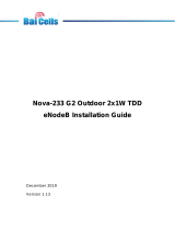
Scenario 2: InstaSPIN-MOTION Speed Control with a Mechanical Sensor
While sensorless solutions are appealing and cost effective for many applications, there are some
applications that require the rigor and accuracy of a mechanical sensor. For these applications (see
Figure 9), the quadrature encoder provides position information, which is then converted to speed
feedback via the SpinTAC Position Convert. SpinTAC Velocity Control receives the speed feedback and
generates the torque reference signal via IqRef. The SpinTAC Motion Control Suite provides the motion
sequence state machine, generates the reference trajectory, and controls the system speed.
15
SPRUHJ0B–April 2013–Revised March 2014 TMS320F28069M, TMS320F28068M InstaSPIN™-MOTION Software
Submit Documentation Feedback
Copyright © 2013–2014, Texas Instruments Incorporated


www.ti.com
InstaSPIN-MOTION Block Diagrams
Scenario 3: InstaSPIN-MOTION Position Control with Mechanical Sensor and redundant FAST
Software Sensor
There are many applications where precise position control is required. For these applications, it is difficult
to balance the many tuning parameters that are required. InstaSPIN-MOTION features accurate position,
speed, and torque control with combined position and speed single-variable tuning (see Figure 10). This
simplifies the tuning challenge and allows you to focus on your application and not on tuning your motor.
Position applications require a mechanical sensor in order to precisely identify the motor angle at zero and
very low speeds. The FAST Software Encoder may provide redundancy in position control applications;
this can be used as a safety feature in case the mechanical encoder fails.
17
SPRUHJ0B–April 2013–Revised March 2014 TMS320F28069M, TMS320F28068M InstaSPIN™-MOTION Software
Submit Documentation Feedback
Copyright © 2013–2014, Texas Instruments Incorporated

SVM
Iq
PI
Speed
PI
INV
PARK
CLARKE
CLARKE
PARK
Id
PI
Traj
Ramp
&^d¡
Software Encoder
Rotor Flux Observer
Motor Parameters ID
DRV_run
+
+
User_I
qRef
User_I
dRef
V
q
V
d
V
r_out
V
t_out
T
a
T
b
T
c
I
a
I
b
I
c
V
a
V
b
V
c
V
bus
V
r_in
V
t_in
I
q_ref
I
q
I
d_ref
I
d
Z
ref
I
d
I
q
I
r_in
I
t_in
Angle
Speed
Flux
Torque
EST_run
ROM
FLASH/RAM
FLASH/RAM
T
a
Z
a
W
a
\
a
W
a
Z
a
\
a
I
rated
a
T
a
T
Spd
out
Torque
Mode
FLASH/RAM
DRV_readAdcData
DRV_acqAdcInt
CTRL_run
CTRL_setup
^]vd¡D}]}v
Control Suite
Motion
Sequence
Position Mode
User_Pos
Ref
User_Spd
Ref
InstaSPIN-DKd/KE¡
FLASH/RAM
DRV_qepComputeAngles
Qep
Driver
T
Qep
Z
ref
Z
a
ROM
Z
ref
.
ROM
STPOSMOVE_run
STPOSCTL_run
^]vd¡
Position
Plan
Z
lim
FLASH/RAM
^]vd¡
Velocity
Identify
ROM
STVELID_run
Z
lim
..
Z
lim
.
^]vd¡
Position
Move
^]vd¡
Position &
Velocity
Control
T
SP
T
ref
T
M
STPOSPLAN_run
^]vd¡
Position
Converter
FLASH/RAM
STPOSCONV_run
T
Qep
T
a
T
Qep
Angle
Selection
T
T
Z
a
T
M
Z
a
PWM
Driver
ADC
Driver
InstaSPIN-MOTION Block Diagrams
www.ti.com
Figure 10. InstaSPIN-MOTION Position Control with Mechanical Sensor and Redundant FAST Software Sensor
18
TMS320F28069M, TMS320F28068M InstaSPIN™-MOTION Software SPRUHJ0B–April 2013–Revised March 2014
Submit Documentation Feedback
Copyright © 2013–2014, Texas Instruments Incorporated

www.ti.com
Application Examples
4 Application Examples
InstaSPIN-MOTION is ideal for applications that require accurate speed and position control, minimal
disturbance, and for applications that undergo multiple state transitions or experience dynamic changes. A
few examples are provided in the following sections.
4.1 Treadmill Conveyor: Smooth Motion Across Varying Speeds and Loads
Consistent speed control is critical for treadmill conveyor belts. When a person runs on a treadmill, their
stride disturbs the motion of the belt. The runner's stride will be choppy if the motor driving the belt cannot
quickly provide enough torque to overcome the disturbance. This problem is exacerbated when the user
changes speeds as part of their exercise regime. If the belt does not smoothly accelerate or decelerate it
seems like the treadmill is not operating correctly. In addition, at low speeds when a user steps on the
belt, their weight can cause the belt to stop.
InstaSPIN-MOTION was applied to a commercial treadmill using a 4-HP, 220-V AC induction motor to
drive the conveyor belt. The treadmill was tested across a variable speed range: 42 rpm at the low end to
3300 rpm at top speed.
The customer found that InstaSPIN-MOTION's advanced controller automatically compensated for
disturbances, keeping the speed consistent while running and across changing speeds. The controller
prevented the belt from stopping at low speeds when a load was applied. In addition, a single gain was
used to control the entire operating range.
4.2 Video Camera: Smooth Motion and Position Accuracy at Low Speeds
High-end security and conference room cameras operate at very low speeds (for example, 0.1 rpm) and
require accurate and smooth position control to pan, tilt, and zoom. The motors that drive these cameras
are difficult to tune for low speed, and they usually require a minimum of four tuning sets. In addition, there
can be choppy movement at startup, which results in a shaky or unfocused picture.
InstaSPIN-MOTION was applied to a high-precision security camera driven by a 2-pole BLDC motor with
a magnetic encoder. InstaSPIN-MOTION was able to control both velocity and position using a single
tuning parameter that was effective across the entire operating range. SpinTAC Move was used to control
the motor jerk, resulting in smooth startup.
4.3 Washing Machine: Smooth Motion and Position Accuracy at Low Speeds
Cycle transitions, changing loads, and environmental disturbances cause significant wear and tear on
motors. Automatic, real-time reduction of disturbances can extend the life and performance of motors.
Consider washing machines, for example. Figure 11 displays the motion profile for three stages of a
standard washing machine. The first stage represents the agitation cycle, rotating between 250 rpm and -
250 rpm, repeatedly. The second and third stages represent two different spin cycles. The second stage
spins at 500 rpm and the third stage spins at 2000 rpm. This profile was easily created using SpinTAC
Plan [as documented in the TMS320F2802xF InstaSPIN-FOC, TMS320F2806xF InstaSPIN-FOC,
TMS320F2806xM InstaSPIN-MOTION User's Guide (SPRUHJ1)].
19
SPRUHJ0B–April 2013–Revised March 2014 TMS320F28069M, TMS320F28068M InstaSPIN™-MOTION Software
Submit Documentation Feedback
Copyright © 2013–2014, Texas Instruments Incorporated

Application Examples
www.ti.com
Figure 11. Washing Machine Profile
InstaSPIN-MOTION was applied to a washing machine application. The SpinTAC Plan trajectory planning
feature was used to quickly build various states of motion (speed A to speed B) and tie them together with
state based logic (see Figure 5).
The washing machine application was run twice — once using a standard PI controller and once using
LineStream's SpinTAC controller. The data was then plotted against the reference curve for comparison.
Agitation Cycle
During agitation, the motor switched between the 250 rpm and -250 rpm setpoints 20 times. The results,
shown in Figure 12, demonstrate that InstaSPIN-MOTION more closely matched the reference profile.
Additionally, the maximum error for PI was 91 rpm (341 - 250 = 91 rpm); whereas, the maximum error for
SpinTAC was 30 rpm (280 - 250 = 30 rpm).
20
TMS320F28069M, TMS320F28068M InstaSPIN™-MOTION Software SPRUHJ0B–April 2013–Revised March 2014
Submit Documentation Feedback
Copyright © 2013–2014, Texas Instruments Incorporated
/