Page is loading ...

*
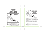
LUBRICATION POINTS
PUNTOS DE LUBRICACIÓN
POINTS DE LUBRIFICATION
OWNER’S MANUAL
Contains:
• Safety Information • Annotated Diagram
• Warranty Information • Trouble Shooting Guide
• Operating Instructions
This safety alert symbol indicates important safety mes-
sages in this manual. When you see this symbol, be alert to the
possibility of personal injury and carefully read the message
that follows.
WARNING: THIS IS NOT A TOY. MISUSE MAY CAUSE
SERIOUS INJURY OR DEATH. EYE PROTECTION DESIGNED
FOR PAINTBALL USE MUST BE WORN BY THE USER AND ANY
PERSON WITHIN RANGE. RECOMMEND AT LEAST 18 YEARS
OLD TO PURCHASE, 14 YEARS OLD TO USE WITH ADULT
SUPERVISION, OR 10 YEARS OLD TO USE ON PAINTBALL
FIELDS MEETING ASTM-STANDARD F1777-02. READ
OPERATION MANUAL BEFORE USING.
WARNING: NEVER SHOOT AT ANYONE WITHOUT
PROPER PROTECTIVE EQUIPMENT FOR EYES, EARS, THROAT
AND HEAD, WHICH MUST BE WORN AT ALL TIMES. EYE
PROTECTION MUST BE DESIGNED SPECIFICALLY FOR
PAINTBALL USE. FAILURE TO FOLLOW THESE SAFETY
PRECAUTIONS MAY RESULT IN BODILY INJURY INCLUDING
BLINDNESS AND DEAFNESS.
Welcome to the JT team and thank you for purchasing this high
quality JT Tetra™ electronic grip marker.
We at JT stand committed to providing you with the best products
and service available. Your new marker is designed and manufactured
to provide ease of maintenance with trouble free performance. We
ask that you read this manual to obtain the maximum enjoyment of
your purchase.
Call 1-800-587-2246 or visit our web site at www.jtusa.com if
you should need an Illustrated Parts List and Troubleshooting
guides.
RULES OF SAFE
PAINTBALL MARKER HANDLING
1. Always wear proper eye, face and ear protection designed
especially to stop paintballs.
2. Never shoot a person who is not wearing proper protection.
3. Treat every paintball marker as if it were loaded.
4. Never look down the barrel of the marker.
5. Never point the paintball marker at anything you don’t wish to shoot.
6. Keep the paintball marker on safe until ready to shoot.
7.
Keep the barrel plug in the paintball marker’s muzzle when not shooting.
8. Always remove gas source before disassembly.
9. Store the paintball marker unloaded and degassed in a locked place.
10. Follow warnings listed on gas source for handling and storage.
11. Never use anything other than .68 caliber paintballs.
12. Do not shoot fragile objects such as windows.
13. Paintballs may cause staining of some porous surfaces such as brick,
stucco and wood.
14. Always measure velocity before playing paintball.
15. Never shoot at velocities in excess of 300 feet per second.
16. Never engage in vandalism.
17. Do not use marker for drive-by shooting.
Use a barrel squeegee to clean broken paintballs from your marker’s bar-
rel. We recommend the JT Battle Swab Squeegee #8401.
DO NOT RETURN THIS MARKER TO YOUR
RETAILER. CALL 1-800-587-2246
NOTE: Any modifications to this product will void all
warranties, whether expressed or implied.
WARRANTY INFORMATION
WARRANTY: LIMITED 90 DAY WARRANTY
(ORIGINAL PURCHASE RECEIPT REQUIRED)
For 90 days from date of purchase, JT USA will repair or replace
this Tetra™ marker free of charge if defective in material or workman-
ship. This warranty gives you specifi c legal rights which may vary
from state to state. Service is available from authorized JT USA Service
Centers. A list of these is available at JT’s website at www.JTUSA.com
or by calling JT USA at 1-800-587-2246. These Service Centers gener-
ally offer the quickest service. If you would rather return your marker
to JT USA please call customer service at 1-800-587-2246 for return
authorization number and shipping address. (Authorization number
must be visible on outside of shipping package to be accepted.) Do
not return any product via non-traceable services such as regular mail
or parcel post. Such products may become lost and JT USA will not
be responsible for replacement.
PAINTBALL MARKERS OUT-OF-WARRANTY
Authorized Service Centers will gladly repair any markers out of war-
ranty for a nominal charge to cover parts and labor. Repairs made by
Service Centers will usually be faster and less expensive than those sent
back to the factory. Go to www.JTUSA.com/service for service center
locations near you. Prior to shipping your out of warranty marker, you
must fi rst call customer service at 1-800-587-2246 for return authoriza-
tion number and shipping address. (Authorization number must be
visible on outside of shipping package to be accepted.) Any out of
warranty Marker returned to JT USA must be shipped prepaid and
include the repair fee. Please call the Customer Service number for
current repair fees. JT USA will repair or replace the marker with a
reconditioned unit of the same model. If payment is not included you
will be billed for the repair fee plus a $4.00 invoicing fee. Upon receipt
of payment , the marker or its replacement will be shipped to you. In
the event that the marker includes no means of contacting the sender
or no payment for the repairs is received within 60 days of billing, the
ownership of the marker will be forfeited and it will be disposed of at
the discretion of JT USA.
WARNING: Never shoot at anyone without proper protective
equipment for eyes. Markers equipped with regulators can store sev-
eral shots in the air system after the air source is removed. Make sure
your marker is in a safe condition before disassembly and maintenance
or removal of barrel plug. Follow the unloading section in this manual.
E-GRIP OPERATION
WARNING: All steps to be
performed without having attached
gas source to marker.
STEP 1. EYE PROTECTION: Make
sure everyone within range (200
yards) is properly protected from
paintball impacts.
STEP 2. PUT ON “SAFE”.
Push mechanical safety from left to
right (SEE FIG. C); no red band show-
ing. Make sure barrel plug is placed
securely in muzzle of marker
STEP 3. INSTALL BATTERY:
Remove grip cover and install sup-
plied 9.6 volt NiMH battery into grip
after connecting battery clip.
(See Fig. B)
STEP 4. TEST: Test for power
before installing grip cover.
STEP 5. TURN ON: Turn marker
on by pushing the On/Off switch
(See Fig. C) forward to on position.
Examine display on left side of the grip
for lighted display. Depress trigger
watch/listen for function.
STEP 6. REPLACE GRIP
COVER (Don’t overtighten screws)
STEP 7. TEST FIRE: Following
the operation instructions below,
first
test fire the marker without paint.
NOTE: Should marker develop func-
tion problems related to the grip, Replace the battery with fully charged
9.6 volt NiMH battery before any other trouble shooting measures.
NOTE: Low battery indicator is located on the grip panel display. Full
charge is a battery with all bars lit. As power decreases in the battery the
indicator will show less bars. Less than 2 bars will give poor performance
during rapid trigger pulls. For best performance recharge your battery
when less than 2 bars are shown.
NOTE: The E-GRIP is semi-automatic fire only.
STEP 8. To turn marker off push On/Off switch to rearward (See Fig. C). When
the marker is off and trigger is activated the grip display will show :JT USA Safe”.
JT USA
LLC.
515 Main Street, Chula Vista, CA 91911 U.S.A.
1-800-587-2246 Fax (619)205-5097
www.jtusa.com
Part No.141223-000 REV: 03/04
OPERATING INSTRUCTIONS
WARNING: Be sure the paintball marker is always pointed in a
safe direction. Read the following operating instructions and WITHOUT
LOADING ANY PAINTBALLS proceed several times through the operat-
ing steps with your paintball marker (dry fire the paintball marker at a
safe target) so that you will be able to operate the marker properly and
safely.
STEP 1. EYE PROTECTION: Make sure everyone within range (200
yards) is properly protected from paintball impacts.
STEP 2. ENGAGE: With safety in the off position and power switch
in the off position, cock marker by pulling cocking pin fully back until
locked in rear position. The Tetra™ is a semi-automatic marker, which
will re-cock itself after firing when working properly.
STEP 3. PUT ON “SAFE”. Push safety from left to right; no red band
showing. Make sure barrel plug is placed securely in barrel of marker.
The safety in this marker is a cross bolt type that blocks movement of
the sear. The marker cannot be cocked or fired while safety is engaged.
Now push on/off switch forward to turn marker on (See Fig. C).
STEP 4. ATTACH GAS SOURCE: Marker can be used with any ASTM
compliant constant air refillable cylinder or CO2 refillable cylinder (not
included). A regulated HPA or compressed air cylinder is suggested for
best performance of this marker (RECOMMEND JT 47 cu. in. constant
air cylinder.). Most preset regulated HPA systems have an output pres-
sure of 750-850 psi.
NOTE: Add 3 drops of mineral oil to the ASA adapter prior to attach-
ing the refillable cylinder. Check the website at: www.jtusa.com for
approved lubricants.
STEP 5. LOAD PAINTBALLS:
A)Insert loader (not included) into ball feed port. Grip loader from the
top. Insert loader feed neck into ball feed port on the marker. Twist
and push firmly in a clockwise direction. (RECOMMEND Viewloader
Quantum
TM
, eVLution II
TM
, Envy
TM
or Revolution
TM
electronic loader)
NOTE: The loader to ball feed port fit is purposely tight.
B) Pour paintballs into loader. Paintballs should be stored in a cool,
dry place in sealed plastic bags. Do not subject to freezing, exces-
sive heat, humidity or store in direct sunlight. These conditions may
cause ball breakage and/or poor feeding. (RECOMMEND Brass Eagle,
Viewloader or JT brand .68 caliber paintballs.)
NOTE: Use a squeegee to clean inside the paintball marker’s barrel.
STEP 6. Now push on/off switch to left to turn on electronic grip.
Remove barrel plug and take off safe by pressing safety from right side
of paintball marker until red band is showing.
STEP 7. VERIFY VELOCITY: Verify that the paintball marker’s
velocity is below 300 feet per second or less if required by playing field.
Velocity should be measured with a chronograph prior to playing
paintball. Velocity may be adjusted by turning the velocity adjustment
screw. (See Fig. A) Using a 1/8” allen key (included) turn the
screw clockwise to increase velocity and counter-clockwise to
decrease velocity.
STEP 8. FIRE: Paintball marker is now ready to fire.
WARNING: Never shoot at anyone without proper protective
equipment for eyes, which must be worn at all times. Eye protection
must be designed specifically for paintball use. Failure to follow these
safety precautions may result in bodily injury including blindness and
deafness.
UNLOADING YOUR TETRA™
WARNING: Always wear proper eye, face and
ear protection designed especially to stop paintballs while unloading
your paintball marker.
STEP 1. Make sure barrel plug is securely in barrel.
STEP 2. Put Tetra™ on safe. (Push safety left to right)
STEP 3. Remove loader.
STEP 4. Turn marker upside down to remove paintballs from feed port.
STEP 5. Remove barrel.
STEP 6. Point marker toward ground in a safe direction and fire several
times to insure it is completely unloaded. Put marker back on safe.
STEP 7. Remove gas source. Should your marker be equipped with a
regulator, fire till no pressure remains in the marker.
STEP 8. Turn marker off by moving on/off switch to right.
STEP 9. Use squeegee to dislodge any paintballs from barrel and
replace barrel plug.
STEP 10. Replace barrel.
Do not unload your marker indoors.
WARNING: Do not look down the breach or barrel of the
marker while gas source is attached.
GENERAL TROUBLESHOOTING
General Maintenance
Use only JT approved parts. NOTE: The use of third party parts such
as o-rings, which could be a slightly different size or hardness, can
result in poor performance due to broken paint, ball hop and rapid
fire. It is critical to the good performance of your marker to use only
JT approved parts. Regular maintenance of your
Marker
is the best
insurance against a problem with your marker in the field. JT USA
recommends that you conduct a general maintenance of your
Marker
after every 1000 paintballs shot. This general maintenance will involve
removal of the bolt and striker and checking the condition of o-rings.
Replacing worn o-rings or lubricating dry o-rings will go a long ways
to preventing a problem while playing. It is recommended that you
use a lubricant that is designed specifically for paintball markers. Go to
www.JTUSA.com for updates on approved marker lubricants.
Gas Leaks
Gas Leaks will occur in the marker because of dirty, dry or damaged
o-rings or seals. There are 8 of these o-rings,washers and seals in your
marker. The most common parts that may require maintenance are;
striker o-ring and cup seal. To obtain JT USA approved parts you should
purchase the JT Marker Repair Kit #0338. This kit contains all of the
parts you need to properly maintain your marker.
FIELD STRIP GUIDE
Bolt and Striker removal
STEP 1. EYE PROTECTION: Make sure everyone within range (200
yards) is properly protected from paintball impacts.
NOTE: After following your unloading instruction in this manual pro-
ceed with the field strip guide.
STEP 2. Remove gas supply from marker.
STEP 3. Make sure cocking pin is in the forward position. Pull trigger to
release if necessary.
STEP 4. Remove top cocking pin and remove bolt (Figure D).
STEP 5. Remove Quick Pull Pin and Remove Velocity Plug, Bumper,
Spring Guide and Spring (Figure E). NOTE: Use caution when removing
as all parts are under spring
tension.
FIELD STRIP
REASSEMBLY
Follow the steps above in
reverse order. Lubricate striker
o-ring with light coat of min-
eral oil. When installing bolt
make sure gas port hole is
facing downward. (Figure D)
Install cocking pin through the
rear bolt hole into striker.(see
Figure F)
STRIKER
REMOVAL AND
REPLACEMENT
STEP 1. Follow Steps
1-5 of Field Strip Guide.
STEP 2. Pull trigger and
tap rear of the receiver
against towel on flat sur-
face to remove striker.
STEP 3. Grasp striker
with fingers and pull from
receiver.
STEP 4. Clean with
soft cloth or baby wipe.
Relubricate with min-
eral oil and replace. NOTE:
Examine o-ring for any
damage and replace if
necessary.
STEP 5. Replace striker
into receiver with sear flat
down. NOTE: It is neces-
sary to pull the trigger 3 or
more times while applying
pressure to striker with
your finger in order to fully seat the striker. (See Figure G)
STEP 6. Reassemble per Field Strip Reassembly Section.
REMOVABLE FEED PORT
VELOCITY PLUG
Taco de Velocidad
Obturateur de Vitesse
BOTTOM-LINE CONSTANT AIR ADAPTER
Adaptador de Aire Constante de Línea Base
Adaptateur d’air constant de ligne de fond
STEEL BRAIDED HOSE
Manguera de Acero Tejido
Tuyau en acier tressé
REMOVABLE BARREL
Cañón Removible
Canon amovible
BARREL PLUG
Tapón del coñon
Obturateur de canon
VELOCITY
ADJUSTMENT
SCREW
Tornillo de
Ajuste de
Velocidad
Vis de réglage de
la vitesse
COCKING PIN
Mango de Percutor
Bouton d’armement
VOLUMIZER PLUG
Tapón de Válvula
Bouchon de soupape
REFILLABLE CYLINDER (not included)
Cilindro Rellenable (no incluida)
Cylindre Réutilisable (non fournie)
.68 CALIBER
SEMI-AUTOMATIC
PAINTBALL MARKER
WITH
ELECTRONIC GRIP
DISASSEMBLY AND CLEANING
OF BALL DETENT
STEP 1. Remove 1/8 hex screw or square headed ball
stop assembly
STEP 2. Remove ball detent.
STEP 3. Clean with soft cloth or baby wipe.
STEP 4. Replace in reverse order. (See Figure H)
NOTE: Ball stop is adjusted for tension on the ball by
screwing hex screw inward a maximum of 2 and one half
turns from flush.
SAFETY
Seguro
Verrou de sécurité
DOUBLE TRIGGER
Gatillo para do Dedos
Détente à deux doigts
FIGURE A - JT TETRA™ MARKER
Figure B
Figure C
ON/OFF SWITCH
Botón ON/OFF
Luz de batería baja
BATTERY LIGHT
Figure D
BOLT
Clavija
Verrou
COCKING PIN
Pasador del Gatillo
Broche D’armement
GAS PORT HOLE
Agujero de Puerta de Gas
Hublot à Gaz
FIgure E
QUICK PULL PIN
Pasador de Tracción
Rápida
Goupille de Traction
Rapide
VELOCITY PLUG
Taco de Velocidad
Obturateur de Vitesse
SPRING
Resorte
Ressort
SPRING GUIDE
Guia De Resorte
Guide-Ressort
BUMPER
Amortiguador
Butoir
COCKING PIN HOLE
Agujero de Pasador del Gatillo
Trou de Broche D’armement
BATTERY CLIP
SUJETADOR
DE BATERÍA
PINCE DE PILE
9.6V NiMH BATTERY
BATERÍA DE 9.6 VOLTIOS
PILE DE 9.6 VOLTS
SOLENOID
Solenoide
Solénoïde
ON/OFF SWITCH
Botón on/off
Luz de batería baja
BALL DETENT
Parada de Bola
Butee a billes
STRIKER
Pecutor
Percuteur
COCKING PIN HOLE
Agujero de Pasador del Gatillo
Trou de Broche D’armement
SEAR FLAT (DOWN)
Fiador Plano (hacia abajo)
Plat de la Gchette (bas)
TETRA ELECTRONIC
GRIP MARKER
Gas leaks at marker/
bottle connection
point
Gas leaks out barrel
Gas leaks through
Volumizer
Marker does not
re-cock
Marker does not
shoot paintballs
straight
Bolt hangs up
Marker double
feeds paintballs
Marker chops
paintballs
Display shows
JTUSA Safe
1. Gas bottle O-ring
dry or defective
2. Gas bottle defective
Cup seal defective
Volumizer O-ring dry
or defective
1. Insufficient gas to
Marker
2. Striker O-ring dry or
defective
3. Bolt O-rings dry or
defective
4. Defect striker spring
5. Excessive gas source
pressure(Omni-
Pressure Valve
Adjustment)
1. Paintball debris in
marker/barrel
2. Out-of-round (old)
paintballs
Bolt hanging up on
paintball debris
1. Ball stop dirty or
broken
2. Missing ball stop
1. Ball stop dirty or
broken
2. Striker O-ring dirty
3. Bolt & receiving
chamber dirty
4. Ball loader not
working properly
5. Defective paintballs
6. Excessive gas source
pressure
1. Trigger to far inward
2. X and Z buttons are
depressed or hung up
-Remove gas bottle from marker
-Lubricate O-ring
-Replace O-ring
-Replace Gas Bottle*
-Replace cup seal
-Remove barrel
-Remove volumizer
-Check O-ring
-Lubricate O-ring or replace
-Check functioning of gas bottle
-Lubricate O-ring or replace
-Lubricate O-ring or replace
-Remove striker spring
-Inspect and replace if appropriate
-Reduce gas source pressure to
below 1500psi.
NOTE: There is no pressure adjust-
ment for CO2 cylinders.
-Remove & clean barrel
-Clean vertical feed adapter
-Clean bolt area
-Replace with fresh paintballs
-Remove barrel
-Remove Bolt Release Pin
-Use wood dowel to release bolt
-Remove bolt and clean bolt and
chamber
-Remove ball stop screws/cover
Replace ball stop
-Remove ball stop
-Clean ball stop or replace
-Remove ball stop
-Clean ball stop or replace
-Remove & clean/replace dirty or
worn O-ring
-Remove bolt & clean
-Swab marker and barrel
-Clean, repair or replace ball loader
Replace ball stop
-Replace paintballs
-Reduce gas source pressure to
below 1500psi.
NOTE: There is no pressure adjust-
ment for CO2 cylinders.
-Readjust trigger hex until trigger
will click.
-Remove right grip space X and Z
microbuttons away from grip frame
with electrically non conductive
material ex. rubber block
PROBLEM POSSIBLE CORRECTIVE
CAUSE(S) ACTION(S)
TROUBLESHOOTING GUIDE
WARNING!: All troubleshooting and corrective actions should begin
with by following the unloading procedure in this manual.
EXPANSION CHAMBER
Cámara de Expansión
Chambre d’expansion
STRIKER
Percutor
Percuteur
STRIKER
Percutor
Percuteur
BOLT
Clavija
Verrou
COCKING PIN
Pasador del Gatillo
Broche D’armement
Figure F
Figure G
BALL DETENT
Ball Detent
Ball Detent
SAFE
DISPLAY SCREEN
BATTERY LIGHT
DISPLAY
SCREEN
OMNI PRESSURE VALVE (patent
pending) ADJUSTMENT
This markers valve and cup seal design is very
unique. Unlike other blowback markers the valve
is dwell adjustable by changing the position of
the volumizer. Dwell is the time a valve remains
open after being struck by the striker assembly.
Previously the adjustable dwell feature has been
available only on the most expensive electronic
markers.
WARNING:
Insure all individuals within 200 feet are
wearing proper eye, face and head protection before
discharging marker.
WARNING:
Before any maintenance or changes to
your air system, volumizer or other pressurized fittings.
Insure the marker is unloaded and contains no pressure
anywhere in the system. Note: The regulator acts as one
way valve for high pressure. If your marker is equipped
with a regulator always insure pressure has been vented
by discharging the marker in a safe direction, after remov-
ing air pressure source. (Please see “Unloading your
Tetra™” in this owner manual)
HOW TO OPERATE OMNI
PRESSURE VALVE:
The Tetra™ is factory set for 800 psi input pressure.
Guidelines for valve/striker spring adjustments at higher
and lower pressure are as follows. For low pressure
operation (400-600 psi) it is best to have the volumizer
unscrewed inward slightly to reduce pressure on the
valve spring (See Fig. I.1) and increase dwell for more air
to the paintball. For high pressure operation (600 to 1000
psi) it is best to have the volumizer screwed outward to
increase pressure on the valve spring (See Fig I.2) this
will decrease dwell for less air to the paintball. The most
efficient dwell for any given pressure may require valve/
striker spring adjustment and some testing at the chrono-
graph for optimal performance (See STEP 7 of Operation
Instructions). Any change in the velocity screw position,
output pressure of a regulated system or fresh filling of
Co2 cylinder will require chronograph of paintball speed
to insure safe playing velocity.
Figure I.1 Figure I.2
The Omni Pressure valve adjustment must be
matched to your air source output pressure.
Consult your air source owner’s manual for output pres-
sure of your regulated HPA cylinders. Co2 cylinders are
generally not regulated and do not have predictable out-
put pressure. If you chose to use a Co2 air source at tem-
peratures greater than 70 degrees. It may be necessary
to add a pressure regulator (not included) to your marker
air system in order to achieve optimal performance from
your marker.
9.6 Volt NiMH BATTERY
(See Fig.A&B)
WARNING:
Use only the supplied charger and 9.6
volt NiMH battery for your JT Tetra™ marker. Use of other
chargers may damage your battery.
Should you need a replacement of battery or char-
ger contact JTUSA at 1-800-587-2246 or go to
www.JTUSA.com
. Installation of the battery is covered
in the E-Grip operation portion of this manual. A fully
charged 9.6 volt NiMH battery will provide greater than
7000 shots. It is not necessary to completely discharge the
battery before recharging. Charging time is dependent
on the amount of energy remaining in the battery when
placed on charge.
9.6 Volt NiMH CHARGER
(See Fig.A)
WARNING:
Do not charge this marker with air
source attached. Before charging insure the marker is
unloaded and safety is engaged.
The supplied charger is 110 volt wall outlet type. To
charge your 9.6 Volt NiMH battery it must be installed in
the marker grip. Installation of the battery is covered in the
E-Grip operation portion of this manual. A charging port is
located on the backside of the marker grip (See Fig. A). A
battery that will accept charge (low voltage) activates the
red light in the charger (See Fig. A). Charge your battery
before first use. Average charge time will be 4 hours. Do
not leave the marker on charge after the LED light turns
green. If the LED has no LED light showing continue to
charge till LED turns green.
GORILLA GRIP FEED NECK
DISASSEMBLY
(PATENT PENDING)
The Tetra™ is equipped with the Gorilla Grip (patent pending)
removable feed neck. It is designed to fi t most loader feed
necks. It is easy to dissemble and clean.
NOTE: Make sure the o-ring is in the correct position before
reattaching feed neck to insure it remains aligned during play.
The feed neck design is purposely tight. Insertion of loader
may require downward pressure and turning to fully seat
the loader into feed neck. Removal may require turning and
upward force on the loader.
GRIP ASSEMBLY RETAINING SCREW (2)
Tornillo de Aseguramiento (2)
Vis d’arrèt (2)
9.6 Volt CHARGER
E-GRIP ELECTRONICS OPERATION
On/off switch (See. Fig. C) is a two or three position switch. Moving
the switch to the right hand position turns electronics off. Moving
the switch to the left hand position turns electronics on. Moving
the three position switch to the 2nd left position activates the Anti-
Chop Eyes (Quadra™ marker only).
WARNING:
Install barrel plug.
Be sure the marker is always
pointed in a safe direction. Read the following electronics operat-
ing instructions, without loading any paintballs, or attaching air
source, proceed several times through the operating steps with
your paintball marker so that you will be sure to operate the
marker safely.
BATTERY CHARGE INDICATOR
(See Fig.C)
Use only the supplied 9.6 volt NiMH rechargeable battery. The dis-
play screen shows an image of 9.6 volt NiMH battery. Full charge
is a battery with all bars lit. As power decreases in the battery the
indicator will show less bars. Less than 2 bars will give poor perfor-
mance during rapid trigger pulls. For best performance recharge
your battery when less than 2 bars are shown. You can recharge
your battery at anytime.
DUAL CONTROL BUTTONS
(See Fig.A)
The rear of the marker grip has two buttons and one 9.6 volt NiMH
battery recharge port. The top button is X. The bottom button is Z.
Button X controls time decrease functions. Button Z controls timing
features and time increase functions.
SERVICE NEEDED MESSAGE:
When the service needed message appears on the display you
will need to follow your Field Strip Guide (See that section) for
regular marker maintenance. Once maintenance is complete,
remove the left side grip cover and lightly depress the red micro
switch button once. Pressing the red button will reset the service
needed shot counter.
GAME TIMER:
(See Fig.C)
The game timer feature is designed to give you control of the
game by allowing you to see time remaining with just a glance of
the display screen. This timer system does not give auditory warn-
ings. To use the game timer turn marker on and press button Z for
3 seconds. The marker will default to factory timer settings or the
last settings you entered. To change pregame and game settings
press the X button to adjust the time upward by 10 sec intervals.
To adjust the time downward by 10 sec intervals press the Z but-
ton. If you are not in a goggles on/safe area for marker discharge
then insure the safety is in the on position with no red band show-
ing. To activate the timer pull the trigger once. Once the timer is
activated it cannot be reset without turning marker off and repeat-
ing the above process.
GAME MANAGER:
(See Fig.C)
The game manager feature is designed to compliment the game
timer system by showing a player time milestones critical for
effective team play. The visual signal for these time milestones is a
flashing display screen. To set the game manager system follow
the above game timer instructions. Next press the Z button for 3
seconds to set milestone A. You have access to 4 game time mile-
stones A-D. To adjust time milestone upward in 10 sec intervals
press button X, to adjust this time downward press button Z. To
move on to the next time milestone B-D press and hold button X
for longer than one second. If you have set time milestones the
system will activate for game play when the game timer feature is
chosen. See game timer instructions.
TOTAL SHOTS:
(See Fig.C)
Your marker keeps count of every time the trigger switch is activat-
ed while the marker is on. You can display the total marker shots
by pressing the Z button for 3 seconds, 3 times after the marker is
turned on. This feature is much like a car odometer. The total shot
count cannot be reset.
TRI-TOUCH TRIGGER
ADJUSTMENT:
(See Fig.A)
The trigger has three hex screws for adjustment. Adjustments
include over travel, trigger switch and trigger set. Two hexes are vis-
ible on the trigger. Trigger set hex is inside grip frame (See Fig. A).
WARNING: Over adjustment of hex screws may damage
trigger switch or cause marker to discharge when turned on.
Install barrel plug.
Be sure the marker is always pointed in a safe
direction. Read the following trigger set screws instructions and
after any adjustments, without loading any paintballs, or attach-
ing air source, proceed several times through the operating steps
with your paintball marker so that you will be sure to operate the
marker safely.
BUTTON X
BUTTON Z
CHARGER PORT
Red/Green LED
Figure H
low pressurehigh pressure
To obtain JT USA approved parts you should purchase
the JT Marker Repair Kit #0338. This kit contains all of
the parts and instructions you need to properly main-
tain your marker.
TRIGGER SET HEX
/