HOO 503
5019 100 75026 LI01UA
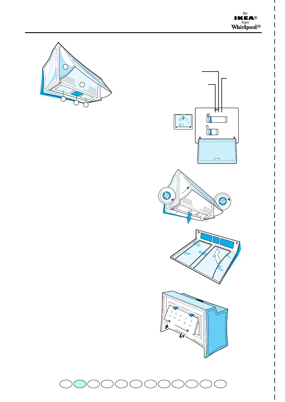
1.
Control panel.
2.
Grease filter (inside the extractor grille)
3.
Lighting unit
4.
Pull-out Steam deflector (extractable)
REMOVING AND SUBSTITUTING OR
CLEANING THE GREASE FILTER:
1.
Unplug the appliance or switch off the mains
power supply.
2.
Pull out the steam deflector.
3.
Open the extractor grille.
4.
Remove the grease filter fixing device.
5.
Remove the dirty grease filter.
6.
After substituting or cleaning the grease filter
(depending on model) remount in reverse
order, making sure the entire extraction
surface is covered.
MOUNTING OR REPLACING THE
CARBON FILTER:
1.
Unplug the appliance or switch off the mains
power supply.
2.
Pull out the steam deflector.
3.
Open the extractor grille.
4.
if the carbon filter is mounted and needs
substituting, press the buttons (
d
) on the filter
and fit a new filter.
5.
if the filter is not mounted.
Fit the carbon filter into the upper clips (
c
).
Fix securely using the lower clips (
d
).
6.
Remount the extractor grille.
REPLACING BULBS
1.
Unplug the appliance or switch off the mains
power supply.
2.
Pull out the steam deflector.
3.
Open the extractor grille.
4.
Remove the burnt-out bulb.
Use 40W max (E14) bulbs only.
5.
Remount the extractor grille.
CONTROL PANEL
A.
Light switch.
B.
Speed selector.
2
4
3
1
3
a
b
b
c
b
b
Medium amount of
steam and fumes
large
amount of
steam and
fumes
small amount of
steam and
fumes
B
A
PRODUCT DESCRIPTION SHEET
F NL E PGBD S DK N FINGRI


