BD-Sensors-Str.1; 95199 Thierstein, Germany
Phone: +49 (0) 92 35 98 11 0 | www.bdsensors.de
© 2021 BD|SENSORS GmbH - All rights reserved.
Operating Manual
Pressure transmitters / screw-in transmitters for IS-areas
DX14-DMK 351, DX14-DMK 351 P, DX14-LMK 351,
DX14B-DMK 387,
DX19-DMK 331, DX19-DMK 331 P, DX19-DMP 311,
DX19-DMP 321, DX19-DMP 331, DX19-DMP 331 i,
DX19-DMP 331 P, DX19-DMP 331 Pi, DX19-DMP 333,
DX19-DMP 333 i, DX19-DMP 334, DX19-DMP 335,
DX19-DMP 336, DX19-DMP 339, DX19-DMP 343,
DX19-LMK 331, DX19-LMP 331, DX19-LMP 331i,
DX19-17.600G, DX19-17.605G, DX19-26.600G
READ THOROUGHLY BEFORE USING THE DEVICE
KEEP FOR FUTURE REFERENCE
ID: BA_DMU-ES_EX_E | Version: 01.2021.0
1. General and safety-related information on
this operating manual
This operating manual enables safe and proper handling of the
product, and forms part of the device. It should be kept in close
proximity to the place of use, accessible for staff members at
any time.
All persons entrusted with the mounting, installation, putting into
service, operation, maintenance, removal from service, and
disposal of the device must have read and understood the
operating manual and in particular the safety-related information.
The following documents are an important part of the
operating manual:
- Data sheet
- Type-examination certificate
For specific data on the individual device, please refer to the
respective data sheet.
Download these by accessing www.bdsensors.de or request
The IS versions of our products are variants of the standard
products.
Example:
Standard: DMK 351 IS version: DX14-DMK 351
In addition, the applicable accident prevention regulations,
safety requirements, and country-specific installation standards
as well as the accepted engineering standards must be
observed.
For the installation, maintenance and cleaning of the device, the
relevant regulations and provisions on explosion protection
(VDE 0160, VDE 0165 and/or EN 60079-14) as well as the
accident prevention regulations must absolutely be observed.
The device was designed by applying the following standards:
DX14: EN 60079-0:2012+A11:2013
EN 60079-11-2012
EN 60079-26:2007
DX14B: EN 60079-0:2018
EN 60079-11:2012
IEC 60079-0: 2017 Edition 7
IEC 60079-11: 2011 Edition 6
DX19: EN IEC 60079-0:2018
EN 60079-11:2012
IEC 60079-0: 2011 Edition 6
IEC 60079-11: 2011 Edition 6
1.1 Symbols used
- Type and source of danger
- Measures to avoid the danger
Warning word Meaning
- Imminent danger!
- Non-compliance will result in
death or serious injury.
- Possible danger!
- Non-compliance may result in
death or serious injury.
- Hazardous situation!
- Non-compliance may result in
minor or moderate injury.
NOTE - draws attention to a possibly hazardous situation that
may result in property damage in case of non-compliance.
Precondition of an action
1.2 Staff qualification
Qualified persons are persons that are familiar with the
mounting, installation, putting into service, operation,
maintenance, removal from service, and disposal of the product
and have the appropriate qualification for their activity.
This includes persons that meet at least one of the following
three requirements:
- They know the safety concepts of metrology and
automation technology and are familiar therewith as
project staff.
- They are operating staff of the measuring and
automation systems and have been instructed in the
handling of the systems. They are familiar with the
operation of the devices and technologies described in
this documentation.
- They are commissioning specialists or are employed in
the service department and have completed training that
qualifies them for the repair of the system. In addition,
they are authorized to put into operation, to ground, and
to mark circuits and devices according to the safety
engineering standards.
All work with this product must be carried out by qualified
persons!
1.3 Intended use
The device is intended for converting the physical parameter of
pressure into an electric signal. It has to be used only for this
purpose, considering the following information.
The above listed pressure transmitters have, according to the
type, been developed for applications in overpressure and
vacuum as well as for absolute pressure measurement.
The screw-in transmitters are intended for level and process
measurement.
Devices with 3-A and / or EHEDG certified process connection
have been developed especially for applications in food and
pharmaceutical industry. The process connection is hygienic and
can be sterilized.
Permissible measuring and cleaning media are gases or liquids,
which are compatible with the media wetted parts of the device
(according to data sheet) and your system. This must be
ensured for the application.
This operating manual applies to devices with explosion
protection approval and is intended for the use in IS-areas.
A device has an explosion-protection approval if this was
specified in the purchase order and confirmed in our order
acknowledgement. In addition, the manufacturing label includes
a sign.
The user must check whether the device is suited for the
selected use. In case of doubt, please contact our sales
BD|SENSORS assumes no liability for any wrong selection and
the consequences thereof!
The technical data listed in the current data sheet are engaging
and must absolutely be complied with. If the data sheet is not
available, please order or download it from our homepage:
http://www.bdsensors.de
1.4 Incorrect use
WARNING
Danger through incorrect use
- Only use the device in permissible
media and in accordance with its
intended use.
- Do not use the device as a ladder or
climbing aid.
- The device must not be altered or
modified in any way.
- BD|SENSORS is not liable for damage
caused by improper or incorrect use.
1.5 Limitation of liability and warranty
Failure to observe the instructions or technical regulations,
improper use and use not as intended, and alteration of or
damage to the device will result in the forfeiture of warranty
and liability claims.
1.6 Safe handling
NOTE - Do not use any force when installing the device to
prevent damage of the device and the plant!
NOTE - Treat the device with care both in the packed and
unpacked condition!
NOTE - Do not throw or drop the device!
NOTE - Excessive dust accumulation and complete coverage
with dust must be prevented!
NOTE - The device is state-of-the-art and is operationally
reliable. Residual hazards may originate from the device if it is
used or operated improperly.
1.7 Safety-related maximum values
DX14- … / DX14B-…:
Ui = 28 V, Ii = 93 mA, Pi = 660 mW, Ci = 27 nF/49,2 nF/14 nF,
Li = 5 µH; Cgnd = 27 nF/100 nF
plus cable inductivities 1 µH/m and
cable capacities 160 pF/m (for cable by factory)
application in zone 0 (patm 0.8 bar up to 1.1 bar): -20 ... 60 °C
DX14: application in zone 1 and higher: -25 ... 70 °C
DX14B: application in zone 1 and higher: -25 ... 65 °C
devices with temperature class T6: -25 … 60°C
DX19-…:
Ui = 28 V; Ii = 93 mA; Pi = 660 mW; Ci ≈ 0 nF; Li ≈ 0 µH;
27 nF opposite GND;
plus cable inductivities 1 µH/m and
cable capacities 160 pF/m (for cable by factory)
application in zone 0 (patm 0.8 bar up to 1.1 bar): -20 ... 60 °C
application in zone 1 and higher: -40/-20 ... 70 °C
application in zone 1 and higher for type DX19- *** i:
-40/-20 ... 65 °C
1.8 Scope of delivery
Check that all parts listed in the scope of delivery are included
free of damage, and have been delivered according to your
purchase order:
- pressure transmitter or screw-in transmitter
- for mechanical pressure ports DIN 3852:
O-ring (pre-mounted)
- this operating manual
- for SIL2 version: safety data sheet
1.9 UL approval (for devices with UL marking)
The UL approval was effected by applying the US standards,
which also conform to the applicable Canadian standards on
safety.
Observe the following points so that the device meets the
requirements of the UL approval:
- only indoor usage
- maximum operating voltage: according to data sheet
- The device must be operated via a supply with energy
limitation (acc. to UL 61010) or an NEC Class 2 energy
supply.
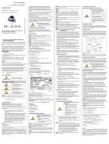
2. Product identification
The device can be identified by means of the manufacturing
label with order code. The most important data can be gathered
therefrom.
Fig. 1: Example of manufacturing label
NOTE - The manufacturing label must not be removed!
The marking for devices with explosion-protection approval
has to include following information:
DX 14:
EU-type examination certificate IBExU05ATEX1070 X
marking:
II 1G, II 1/2G or II 2G Ex ia IIC/IIB T6/T4 Ga, Ga/Gb or Gb
II 1D Ex ia IIIC T85°C Da
DX 14B:
EU-type examination certificate IBExU15ATEX1066 X
marking:
II 1G Ex ia IIB T4 Ga/II 2G Ex ia IIC T4 Gb
II 1D Ex ia IIIC T135 °C Da
DX 19:
EU-type examination certificate IBExU10ATEX1068 X
marking:
non-metallic pressure port: II 2G Ex ia IIC T4 Gb
II 2D Ex ia IIIC T85°C Db
metallic pressure port: II 1G Ex ia IIC T4 Ga
II 1D Ex ia IIIC T135°C Da.
3. Mounting
3.1 Mounting and safety instructions
DANGER
Danger of death from explosion,
airborne parts, leaking fluid, electric
shock
- Always mount the device in a
depressurized and de-energized
condition!
- Do not install the device while there is
a risk of explosion.
DANGER
Danger of death from explosion
- Explosion hazard due to high-charging
processes in connection with free-
hanging submersible transmitters with
cable FEP
- Fixed installation of the FEP cable!
NOTE - The technical data listed in the EU-type examination
certificate are binding. Download this by accessing
www.bdsensors.de or request it by e-mail or phone:
NOTE - Make sure that the entire interconnection of
intrinsically safe components remains intrinsically safe. The
owner-operator is responsible for the intrinsic safety of the
overall system (entire circuitry).
NOTE - If there is increased risk of damage to the device by
lightning strike or overvoltage, increased lightning protection
must additionally be provided!
NOTE - Treat any unprotected diaphragm with utmost care;
this can be damaged very easily.
NOTE - Provide a cooling line when using the device in steam
piping and clarify the material compatibility.
NOTE - The measuring point must be designed in such a way
that cavitation and pressure surges are avoided.
NOTE - When installing the device, avoid high mechanical
stresses on the pressure port! This will result in a shift of the
characteristic curve or to damage, in particular in case of very
small pressure ranges and devices with a pressure port made of
plastic.
NOTE - In hydraulic systems, position the device in such a
way that the pressure port points upward (ventilation).
NOTE - If the device is installed with the pressure port pointing
upwards, ensure that no liquid drains off on the device. This
could result in humidity and dirt blocking the gauge reference in
the housing and could lead to malfunctions. If necessary, dust
and dirt must be removed from the edge of the screwed joint of
the electrical connection.
NOTE - Do not remove the packaging or protective caps of the
device until shortly before the mounting procedure, in order to
exclude any damage to the diaphragm and the threads!
Protective caps must be kept! Dispose of the packaging
properly!
NOTE - The permissible tightening torque depends on the
conditions on site (material and geometry of the mounting point).
The specified tightening torques for the pressure transmitter
must not be exceeded!
NOTES - for mounting outdoors or in a moist
environment:
- Please note that your application does not show a dew point,
which causes condensation and can damage the pressure
transmitter. There are specially protected pressure
transmitters for these operating conditions. Please contact us
in such case.
- Connect the device electrically straightaway after mounting or
prevent moisture penetration, e.g. by a suitable protective
cap. (The ingress protection specified in the data sheet
applies to the connected device.)
- Select the mounting position such that splashed and
condensed water can drain off. Stationary liquid on sealing
surfaces must be excluded!
- If the device has a cable outlet, the outgoing cable must be
routed downwards. If the cable needs to be routed upwards,
this must be done in an initially downward curve.
- Mount the device such that it is protected from direct solar
radiation. In the most unfavourable case, direct solar radiation
leads to the exceeding of the permissible operating
temperature. This must be excluded if the device is used in
any explosion-hazardous area!
- For devices with gauge reference in the housing (small hole
next to the electrical connection), install the device in such a
way, that the gauge reference is protected from dirt and
moisture. Should the device be exposed to fluid admission,
the functionality will be blocked by the gauge reference. An
exact measurement in this condition is not possible.
Furthermore, this can lead to damages on the device.
3.2 Conditions for devices with 3-A symbol
and / or EHEDG certificate
The device or its connecting piece must be installed in such a
way that the surfaces are self-draining (permissible installation
position 273° … 87°).
Make sure that the welding socket is mounted flush inside the
tank.
The user is responsible for:
- the correct size of the seal and the choice of an
elastomeric sealing material that complies with the
3-A and / or EHEDG standard(s)
- an easy to clean installation position of the pressure
transmitter with little dead space, as well as definition /
verification / validation of a suitable cleaning process
- defining adequate service intervals
3.3 Conditions for oxygen applications
DANGER
Danger of death from explosion
- when used improperly
Make sure that your device was ordered for oxygen applications
and delivered accordingly. (see manufacturing label - ordering
code ends with the numbers "007")
Unpack the device directly prior to the installation.
Skin contact during unpacking and installation must be avoided
to prevent fatty residues remaining on the device.
Wear safety gloves!
The entire system must meet the requirements of BAM
(DIN 19247)!
For oxygen applications > 25 bar, devices without seals are
recommended.
Transmitters with o-rings of FKM (Vi 567):
permissible maximum values: 25 bar / 150° C (BAM approval)
3.4 Mounting steps for connections according
to DIN 3852
NOTE - Do not use any additional sealing material such as
yarn, hemp or Teflon tape!
The O-ring is undamaged and seated in the designated
groove.
The sealing face of the mating component has a flawless
surface. (RZ 3.2)
1 Screw the device into the corresponding thread by hand.
2 Devices equipped with a knurled ring:
only tighten by hand
3 Devices with a spanner flat must be tightened using a
suitable open-end wrench. Permissible tightening torques
for pressure transmitter:
- wrench flat made of steel:
G1/4": approx. 5 Nm G1/2": approx. 10 Nm
G3/4": approx. 15 Nm G1": approx. 20 Nm
- wrench flat made of plastic: max. 3 Nm
3.5 Mounting steps for connections according
to EN 837
A suitable seal for the medium and the pressure to be
measured is available. (e.g. a copper seal)
The sealing face of the mating component has a flawless
surface. (RZ 6.3)
1 Screw the device into the corresponding thread by hand.
2 Then tighten it using an open-end wrench. Permissible
tightening torques for pressure transmitter:
G1/4": approx. 20 Nm; G1/2": approx. 50 Nm
NOTE - permitted pressure ranges according to EN 837
G1/4"
EN 837 pN ≤ 600 bar Counterpart has to be of
steel according to
DIN 17440 with strength
Rp 0.2 ≥ 190 N/mm2
G1/2"
pN ≤ 1000 bar
G1/4"
pN > 600 bar,
N
Counterpart has to be of
steel according to
DIN 17440 with strength
Rp 0.2 ≥ 260 N/mm2
G1/2"
pN > 1000 bar,
N
3.6 Mounting steps for NPT connections
Suitable fluid-compatible sealing material, e.g. PTFE tape,
is available.
1 Screw the device into the corresponding thread by hand
2 Then tighten it using an open-end wrench. Permissible
tightening torques for pressure transmitter:
1/4" NPT: approx. 30 Nm; 1/2" NPT: approx. 70 Nm
3.7 Mounting steps for internal threads M20x1.5 and
9/16" UNF (for high-pressure devices)
Danger of injury
- Due to wrong installation
- Do not use any seal!
NOTE - The high-pressure tube will seal metal-to-metal in the
chamfer of the pressure port. (sealing cone 60°)
1 Screw the high-pressure fitting into the internal thread of
the pressure transmitter.
2 Then tighten it using an open-end wrench. The required
tightening torque depends on the manufacturer's
specifications for the high-pressure pipe you are using.
(permissible tightening torque for pressure transmitter:
max 120 Nm)
3.8 Mounting steps for dairy pipe connections
The O-ring is undamaged and seated in the designated
groove.
Chapter "3.2” has been noticed.
EHEDG conformity is only ensured in combination with
an approved seal. This is e.g.:
ASEPTO-STAR k-flex upgrade seal by Kieselmann GmbH
1 Centre the dairy pipe connection in the counterpart.
2 Screw the cup nut onto the mounting part.
3 Then tighten it using a hook wrench.
3.9 Mounting steps for Clamp and Varivent
connections
A suitable seal for the measured fluid and the pressure to
be measured is available.
Chapter "3.2” has been noticed.
EHEDG conformity is only ensured in combination with
an approved seal. This is e.g.:
for Clamp connections:
T-ring seal from Combifit International B.V.
for Varivent connections:
EPDM-O-ring which is FDA-listed
1 Place the seal onto the corresponding mounting part.
2 Centre the clamp connection or Varivent connection
above the counterpart with seal.
3 Then fit the device with a suitable fastening element (e. g.
semi-ring or retractable ring clamp) according to the
supplier’s instructions.
3.10 Mounting steps for flange connections
A suitable seal for the measured fluid and the pressure to
be measured is available. (e.g. a fiber seal)
1 Put the seal between connecting flange and counter flange
2 Install the device with 4 resp. 8 screws (depending on
flange version) on the counter flange.
4. Electrical connection
4.1 Connection and safety instructions
DANGER
Danger of death from electric shock
or explosion
- Explosion hazard if the operating
voltage is too high (max. 28 VDC) or by
opening the field housing while an
explosion hazard exists.
- Always mount the device in a
depressurized and de-energized
condition!
-
Do not install the device while there is a
risk of explosion.
- Operate the device only within the
specification! (data sheet)
The limit values listed in the EU-type examination certificate
are observed. (Capacity and inductance of the connection
cable are not included in the values.)
The supply corresponds to protection class III (protective
insulation).
NOTE - If the device is equipped with plug ISO 4400 or field
housing, it must be ensured that the external diameter of the
used cable is within the permissible clamping range:
cable socket ISO 4400: Ø 4 … 6 mm
field housing code 850: Ø 2 … 8 mm
field housing code 880: Ø 5 … 14 mm
Moreover you have to ensure that it lies in the cable gland firmly
and cleftlessly!
NOTE - When devices with ISO 4400 or Buccaneer
connector are used, the cable socket must be properly
mounted so that the ingress protection specified in the data
sheet is ensured! Ensure that the delivered seal is placed
between plug and cable socket. After connecting the cable,
fasten the cable socket on the device by using the screw.
NOTE - On devices with field housing, the terminal clamps
are situated under the metal cap. To install the device
electrically, the cap must be screwed off. The connection must
be made such that the isolation distances according to standard
are observed and that loosening of the connecting lines is
impossible. Before the cap is screwed on again, the O-ring and
the sealing surface on the housing have to be checked for
damages and if necessary to be changed! Afterwards screw the
metal cap on by hand and make sure that the field housing is
firmly locked again.
0637
EU-type examination Safety technical
certificate no., explosion marking maximum values
Type designation Ordering code Serial number