Page is loading ...

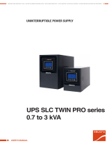
SLC TWIN RT2 LION
1.. 3 kVA
UNINTERRUPTIBLE POWER SUPPLIES (UPS)
USER MANUAL
+41 61 926 90 60 www.sicotec.ch [email protected]
S I CO TEC A G

2
General index.
1. INTRODUCTION.
1.1. THANK YOU LETTER.
2. SAFETY INFORMATION.
2.1. USING THIS MANUAL.
2.1.1. Conventions and symbols used.
3. QUALITY ASSURANCE AND STANDARDS.
3.1. STATEMENT BY THE MANAGEMENT.
3.2. STANDARDS.
3.2.1. First and second environment.
3.2.1.1. First environment.
3.2.1.2. Second environment.
3.3. ENVIRONMENT.
4. PRESENTATION.
4.1. VIEWS.
4.1.1. Views of the device.
4.2. DEFINITION OF THE PRODUCT.
4.2.1. Nomenclature.
4.3. OPERATING PRINCIPLE.
4.4. UPS OPERATING MODES.
4.4.1. Notable features.
4.5. OPTIONAL EXTRAS.
4.5.1. Isolation transformer.
4.5.2. Exterior manual maintenance bypass.
4.5.3. Communication card.
4.5.3.1. Integration into computer networks using an SNMP
adapter.
4.5.3.2. RS-485 modbus.
4.5.3.3. Relay interface.
4.5.4. Extendable guide kits for mounting in a rack cabinet.
5. INSTALLATION.
5.1. RECEPTION OF THE DEVICE.
5.1.1. Reception, unpacking and contents.
5.1.2. Storage.
5.1.3. Unpacking.
5.1.4. Transport to the site.
5.1.5. Siting, immobilising and considerations.
5.1.5.1. Rotation of the control panel with LCD.
5.1.5.2. Vertical tower-type mounting.
5.1.5.3. Mounting as a rack in a 19” cabinet.
5.1.5.4. Preliminary considerations before connection.
5.1.5.5. Preliminary considerations before connection, regarding
the batteries and their protections.
5.1.5.6. Connection elements.
5.2. CONNECTIONS.
5.2.1. Connection of the input.
5.2.2. Connection to the IEC output connectors.
5.2.2.1. Connecting the loads.
5.2.3. Terminals for EPO (emergency power off).
5.2.4. Communication port.
5.2.4.1. RS-232 and USB port.
5.2.5. Smart slot for the integration of an electronic communication
unit.
5.2.6. Protection against voltage spikes for the modem / ADSL /
fax, etc., line. .
5.2.7. Software.
5.2.8. Considerations before startup with connected loads.
6. OPERATION.
6.1. S TA R T-UP.
6.1.1. Checks before start-up.
6.2. UPS STARTUP AND SHUTDOWN.
6.2.1. UPS startup with mains voltage.
6.2.2. UPS startup without mains voltage.
6.2.3. UPS shutdown with mains voltage.
6.2.4. UPS shutdown without mains voltage.
7. CONTROL PANEL WITH LCD.
7.1. GENERAL INFORMATION FOR THE SERIES.
7.1.1. Information represented by the display.
7.1.2. Common messages shown on the LCD display.
7.1.3. Common abbreviations shown on the display.
7.2. CONTROL PANEL
7.2.1. Composition of the control panel with LCD display.
7.2.2. Audible alarms.
7.2.3. Location of the setting parameters on the display.
7.2.4. Settings.
7.2.4.1. Operating mode / Description of state.
7.2.4.2. Warning or alert indicators.
7.2.4.3. Error or fault codes.

3
8. MAINTENANCE, WARRANTY AND SERVICE.
8.1. BATTERY MAINTENANCE.
8.2. UPS TROUBLESHOOTING GUIDE.
8.2.1. Troubleshooting guide.
8.3. WARRANTY CONDITIONS.
8.3.1. Terms of the warranty.
8.3.2. Exclusions.
8.4. TECHNICAL SERVICES NETWORK.
9. ANNEXES.
9.1. GENERAL TECHNICAL SPECIFICATIONS.
9.2. GLOSSARY.
SLC TWIN RT2 LION UNINTERRUPTIBLE POWER SUPPLIES (UPS)USER MANUAL

4
SALICRU
1. INTRODUCTION.
1.1. THANK YOU LETTER.
We thank you in advance for the trust placed in us in the pur-
chasing of this product. Read this instruction manual carefully
in order to familiarise yourself with its content, since the more
you know and understand the device the greater your satisfac-
tion, level of safety and optimisation of its functionalities will
be.
We remain at your disposal for any additional information or
queries that you may wish to make.
Yours sincerely.
•The device described here is capable of causing sig-
nificant physical injury if improperly handled. For this
reason, its installation, maintenance and/or repair must be
carried out exclusively by our staff or qualified personnel.
•Although no effort has been spared to ensure that the in-
formation in this user manual is complete and accurate,
we accept no liability for any errors or omissions that may
exist.
The images included in this document are for illustrative
purposes and may not exactly represent the parts of the
device shown; therefore they are not contractual. However,
any divergence that may arise will be remedied or solved
with the correct labelling on the unit.
•Following our policy of constant evolution, we reserve
the right to modify the characteristics, operations
or actions described in this document without prior
notice.
•Reproduction, copying, assignment to third parties,
modification or total or partial translation of this
manual or document, in any form or by any means, without
previous written permission by us is prohibited, with
the company reserving full and exclusive property rights
over it.


6
3. QUALITY ASSURANCE AND STANDARDS.
3.1. STATEMENT BY THE MANAGEMENT.
Our goal is customer satisfaction, therefore this Management
has decided to establish a Quality and Environment Policy,
through the implementation of a Quality and Environmental
Management System that will enable us to comply with the
requirements demanded in the ISO 9001 and ISO 14001 and
also by our Customers and Stakeholders.
Likewise, the management of the company is committed to
the development and improvement of the Quality and Environ-
mental Management System, through:
•Communication to the entire company of the importance
of satisfying both the customer's requirements as well as
legal and regulatory requirements.
•The dissemination of the Quality and Environment Policy
and the setting of the Quality and Environment objectives.
•Conducting reviews by the Management.
•Providing the necessary resources.
3.2. STANDARDS.
The SLC TWIN RT2 LION is designed, manufactured and sold in
accordance with Quality Management Standard EN ISO 9001.
The marking indicates conformity with EC Directives through
the application of the following standards:
•2014/35/EU. - Low-voltage safety.
•2014/30/EU. - Electromagnetic Compatibility (EMC).
•2011/65/EU. - Restriction of the use of hazardous sub-
stances in electrical and electronic equipment (RoHS).
In accordance with the specifications of the harmonised stand-
ards. Reference standards:
•EN-IEC 62040-1. Uninterruptible power supplies (UPS).
Part 1-1: General and safety requirements for UPS used in
user access areas.
•EN-IEC 62040-2. Uninterruptible power supplies (UPS).
Part 2: EMC requirements.
The manufacturer is not liable in the event of modifica-
tion or intervention on the device by the user.
WARNING:
SLC TWIN RT2 LION from 1 to 3 kVA. This is a category
C2 UPS. In a residential environment, this product may
cause radio interference, in which case the user must
take additional measures.
It is not appropriate to use this device in basic life sup-
port applications (BLS), where a failure of the former
can render vital equipment out of service or signifi-
cantly affect its safety or effectiveness. It is also not
recommended in medical applications, commercial
transport, nuclear installations, or other applications or
loads, where a failure of the product can lead to per-
sonal or material damages.
The EC declaration of conformity of the product is avail-
able to the customer upon express request to our offices.
3.2.1. First and second environment.
The environment examples that follow cover most UPS instal-
lations.
3.2.1.1. First environment.
Environment including residential, commercial and light in-
dustry installations, directly connected, without intermediate
transformers, to a low voltage public power grid.
3.2.1.2. Second environment.
An environment that includes all commercial, light industrial
and industrial establishments that are not directly connected
to a low voltage power grid supplying buildings used for resi-
dential purposes.
3.3. ENVIRONMENT.
This product has been designed to respect the environment
and has been manufactured in accordance with the ISO14001
standard.
Recycling of the device at the end of its useful life:
We undertake to use the services of authorised and regulatory-
compliant companies to process all of the products when they
are recovered at the end of their useful life (contact your dis-
tributor).
Packaging:
For the recycling of the packaging there must be compliance
with the legal requirements in force, in accordance with the
specific regulations of the country where the device is installed.
Batteries:
Batteries pose a serious hazard to health and the environment.
They must be disposed of in accordance with the laws in force.

7
4. PRESENTATION.
4.1. VIEWS.
4.1.1. Views of the device.
Fig. 1 and Fig. 2 show illustrations of the devices according to
box format and in relation to the model’s power rating. How-
ever, because the product is constantly evolving, discrepancies
or slight contradictions may arise. If in any doubt, the labelling
on the device itself will always prevail.
The nameplate of the device shows all of the values re-
lating to its main properties and characteristics. Act
accordingly for its installation.
Control
panel with
LCD
Plastic front
trim
Fig. 1. Front view.
IEC output connectors
programmable at disconnection,
for non-critical loads
COM port
USB
RS-232 port
AC power
IECconnector
Smart slot
protective cover
Fan
Connector for
external EPO
I/O connectors with protection
for modem/ADSL/fax, etc.
Earth
connection
Non-programmable IEC output
connectors, for critical loads
IEC output connectors
programmable at disconnection,
for non-critical loads
COM port
USB
RS-232 port
AC power
IECconnector
Smart slot
protective cover
Fan
Connector for
external EPO
I/O connectors with protection for
modem/ADSL/fax, etc.
Earth
connection
Non-programmable IEC output
connectors, for critical loads
IEC output connectors
programmable at disconnection,
for non-critical loads
COM port
USB
RS-232 port
AC power
IECconnector
Smart slot
protective cover
Fan
Connector for
external EPO
I/O connectors with protection
for modem/ADSL/fax, etc.
Earth
connection
Non-programmable IEC output
connectors, for critical loads
16 A IEC output
connector
SLC 1000/1500 TWIN RT2 LION
SLC 2000 TWIN RT2 LION
SLC 3000 TWIN RT2 LION
Fig. 2. Rear view of the the SLC TWIN RT2 LION models.
SLC TWIN RT2 LION UNINTERRUPTIBLE POWER SUPPLIES (UPS)USER MANUAL

8
4.2. DEFINITION OF THE PRODUCT.
4.2.1. Nomenclature.
SLC-3000-TWIN RT2 LION WCO EE29503
EE* Special customer specifications.
CO ‘Made in Spain’ marking on UPS and packaging (for
customs purposes).
W Private-label device.
TWIN RT2 LION Device series.
3000 Power in VA.
SLC Brand acronym (for UPS).
4.3. OPERATING PRINCIPLE.
This manual describes the installation and operation of the SLC
TWIN RT2 LION series of Uninterruptible Power Supplies (UPS).
SLC TWIN RT2 LION series UPSs ensure optimum protection of
any critical load, maintaining the supply voltage of the loads
between the specified parameters without interruption during
failure, deterioration or fluctuation of mains power.
Thanks to their PWM (pulse width modulation) and double-
conversion technology, SLC TWIN RT2 LION series UPSs are
compact, cool, silent and high performance.
The double converter principle eliminates all mains power dis-
turbances. A rectifier converts the AC current of the mains into
DC current, thereby maintaining optimum battery charge level
and powering the inverter, which, in turn, generates a suitable
AC sine-wave voltage for continuously powering the loads. In
the event that the UPS’s input power supply fails, the Li-ion
batteries will supply clean power to the inverter.
The design and construction of the SLC TWIN RT2 LION se-
ries UPS has been carried out in accordance with international
standards.
Consequently, this series has been designed to maximise the
availability of critical loads and to ensure that your business is
protected against any variations in voltage, frequency, electrical
noise, cuts or dropouts that may occur in the power supply. This
is the primary goal of SLC TWIN RT2 LION series UPSs.
This manual applies to the standardised models shown in Tab. 1.
Characteristics and main advantages of Li-ion batteries.
Like lead-acid batteries, lithium-ion (Li-ion) batteries
consist of four components: anode, cathode, electrolyte and
separator.
Two compounds act as electrodes and are immersed in the
electrolyte. The same material, lithium carbonate, is used for
the anode in all Li-ion batteries. The material used for the
cathode can vary. Li-ion batteries use lithium oxide (Li2O).
Main advantages:
•Increased energy density: The accumulator’s energy density
determines the battery’s capacity. The energy density of Li-
ion batteries is approximately three times higher than that
of lead-acid; thus, when comparing Li-ion and lead-acid
batteries of similar size, the capacity of the former would
be three times higher.
•Increased energy efficiency and higher voltage: Lithium is
a highly electronegative chemical element. Its increased
oxidation capacity means the voltage of Li-ion batteries is
higher. While a lead-acid battery cell produces 2 V, a Li-ion
cell produces in excess of 3.6 V.
Overall performance levels, meanwhile, reach 98%.
•Improved energy profile: The energy profile measures the
charge status in relation to charge time and battery use.
Li-ion batteries boast a superior energy profile.
Because they operate at a higher voltage, a less intense
current is needed to produce the same amount of energy,
meaning the battery needs less time to charge.
•Depth of discharge: While the useful life of lead-acid ac-
cumulators can be maximised if they are kept at just 20%
discharge, and it is not recommended to let them discharge
by more than 50%, Li-ion batteries do not suffer from this
problem and can be discharged up to 100%.
•Longer useful life: Following on from the previous point, it
should be noted that the useful life of a deep-cycle lead-
acid monoblock is 600-700 charge-discharge cycles. In con-
trast, the useful life of a Li-ion battery is around 10 times
longer, i.e. 6,000+ cycles.
•Maintenance-free: Li-ion batteries are sealed and do not
require any form of maintenance.

9
4.4. UPS OPERATING MODES.
•Normal mode.
Device running supplying output voltage from the inverter.
Mains power present with correct input voltage and fre-
quency.
•Battery mode.
Device running with mains voltage or frequency out of
range or without AC input power, either due to mains
failure or absence of cable connection, supplying output
voltage from the batteries.
•Bypass mode.
Device running or not, supplying output voltage directly
from the AC mains.
With the inverter running, this operating mode may be due
to an overload, blockage or inverter fault.
The actions for each incident will be as follows: Reduce the
load connected to the output, unblock the device by reset-
ting it - stop it and start it up again - and, if the blockage or
fault remains, contact our T.S.S.
With the inverter shut down, the output supplies mains
power directly through the static bypass of the device pro-
vided that it has AC input power.
•Frequency converter (CF) mode.
Operating mode of the UPS as a frequency converter. In this
mode, the static bypass is disabled by the condition of dis-
parate input and output frequencies.
Even if the LCD on the backlit control panel shows mes-
sages, it does not mean that the inverter is operational.
It is switched on by pressing the ‘ON’ button on the
control panel, see Chapter 6.
4.4.1. Notable features.
•True on-line with double-conversion technology and output
frequency separate from the mains.
•Output power factor 0.9. Pure sine-wave waveform, suit-
able for all types of load.
•Input power factor > 0.99 and high overall performance (be-
tween 89% and 91%). Greater energy savings and lower
user installation costs (wiring), as well as low distortion
of the input current, which reduces pollution in the power
supply network.
•Great adaptability to the worst conditions of the mains.
Wide input voltage, frequency and waveform ranges, thus
avoiding excessive dependence on limited battery power.
•Battery recharge time < 3h.
•Selectable high-efficiency mode (ECO MODE) > 95%. En-
ergy savings, economically beneficial to the user.
•Possibility of starting the device without mains power
supply or discharged battery. Pay attention to this last as-
pect because the more the batteries are discharged, the
more the backup will be reduced.
•Intelligent battery management technology is very useful
for extending the life of accumulators and optimising re-
charge times.
•Standard communication options via the RS-232 serial port
or USB port.
•Remote emergency power off control (EPO).
•Control panel with LCD display.
•Availability of optional connectability cards to improve
communication capabilities.
•The device can be configured as a tower or rack using the
accessories supplied. The control panel can be rotated to
adapt to either format.
Model Type Input/output type
SLC-1000-TWIN RT2 LION
Standard
Single-phase / Single-phase
SLC-1500-TWIN RT2 LION
SLC-2000-TWIN RT2 LION
SLC-3000-TWIN RT2 LION
Tab. 1. Standardised models.
4.5. OPTIONAL EXTRAS.
Depending on the configuration chosen, the device can include
any of the following options:
4.5.1. Isolation transformer.
The isolation transformer provides galvanic isolation in order
to completely isolate the output from the input and/or change
neutral point treatment.
The placement of an electrostatic screen between the primary
and secondary windings of the transformer provides a high
level of electrical noise attenuation.
The isolation transformer can be physically placed at the input
or output of the UPS depending on the technical conditions of
the whole system (device supply voltage and/or load voltage,
characteristics or their type, etc.).
It will always be supplied as a peripheral component external
to the device itself in a separate enclosure.
4.5.2. Exterior manual maintenance bypass.
The purpose of this option is to electrically isolate the device
from the mains and the critical loads without cutting the power
to the latter. In this way, maintenance or repair operations on
the device can be carried out without interruptions to the power
supply of the protected system, while preventing unnecessary
hazards for technical personnel.
SLC TWIN RT2 LION UNINTERRUPTIBLE POWER SUPPLIES (UPS)USER MANUAL

10
4.5.3. Communication card.
The UPS features a slot at the rear for inserting one of the fol-
lowing communication cards.
4.5.3.1. Integration into computer networks using an SNMP
adapter.
Large computer systems based on LANs and WANs that integrate
servers in different operating systems must provide the system
manager with ease of control and administration. This facility
is obtained through an SNMP adapter, which is universally sup-
ported by the main software and hardware manufacturers.
Connection of the UPS to the SNMP is internal while that of the
SNMP to the computer network is made through an RJ-45 10
base connector.
4.5.3.2. RS-485 modbus.
Large computer systems based on LANs and WANs often re-
quire that communication with any element that is integrated
into the computer network be made through a standard indus-
trial protocol.
One of the most used standard industrial protocols on the
market is the MODBUS protocol.
4.5.3.3. Relay interface.
The UPS has, as an option, a relay interface card that provides
digital signals in the form of potential-free contacts, with a
maximum applicable voltage and current of 240 V AC or 30 V
DC and 1 A.
This communication port enables dialogue between the device
and other machines or devices through the relays supplied in
the terminal block arranged on the same card, with a single
common terminal for all of them.
From the factory, all contacts are normally open and can be
changed one by one, as indicated in the information supplied
with the optional extra.
The most common use of these types of ports is to provide the
necessary information to the file-closing software.
For more information, contact our T.S.S. or our nearest dis-
tributor.
4.5.4. Extendable guide kits for mounting in a rack cabinet.
An extendable and unique guide kit is available for all device
models, valid for any kind of rack-type cabinet.
These guides enable any TWIN RT2 LION unit to be installed like
a rack in its respective cabinet.

11
5. INSTALLATION.
Read and respect the Safety Information, described in
Chapter 2 of this document. Failure to obey some of the
instructions described in this manual can result in a serious or
very serious accident to persons in direct contact or in the vi-
cinity, as well as failures in the device and/or loads connected
to it.
In addition to the device’s own user manual, a number of other
documents are supplied along with the Quick Start guide. Con-
sult them and strictly follow the indicated procedure.
5.1. RECEPTION OF THE DEVICE.
Pay attention to section 1.2.1. of the safety instructions
-EK266*08- in all matters relating to the handling, movement
and siting of the unit.
Use the most suitable means to move the UPS while it is
packed, with a pallet jack or forklift.
Any handling of the device must be carried out in accordance
with the weights shown in the technical specifications ac-
cording to the model, indicated in Chapter 9. Annexes.
5.1.1. Reception, unpacking and contents.
•Reception. Check that:
The data on the label affixed to the packaging corre-
sponds to that specified on the order. Once the UPS is
unpacked, check the previous data with those of the
device nameplate.
If there are discrepancies, report the issue as soon as
possible, citing the device’s manufacturing number and
delivery note references.
It has not suffered any mishaps during transportation
(packaging in perfect condition).
If this is not the case, contact your distributor.
•Unpacking.
To check the contents, it will be necessary to remove
the packaging.
Complete the unpacking according to the
procedure of section 5.1.3.
•Contents.
1 UPS.
Quick guide on paper.
Information for warranty registration.
1 USB cable.
3 cables with IEC connectors for loads.
1 cable for the device’s AC power supply.
2 metal pieces for use as handles and screws for in-
stalling the unit in a rack cabinet.
4 plastic pieces for use as a base and screws to
facilitate the arrangement of the UPS as a tower
(vertical position).
Once the reception is completed, it is advisable to re-pack the
UPS until it is put into service in order to protect it against me-
chanical shock, dust, dirt, etc.
The device’s packaging consists of a cardboard box, expanded
polystyrene corners and polyethylene cover and strapping, all
of which can be recycled. When the packaging requires dis-
posal, it must be carried out in accordance with current laws.
We recommend keeping the packaging for at least 1 year.
5.1.2. Storage.
The device should be stored in a dry, ventilated location pro-
tected from rain, dust, water splashes and chemical agents. It
is advisable to keep each device and battery unit in its original
packaging, as it has been specifically designed to ensure max-
imum protection during transportation and storage.
For devices that contain Li-ion batteries, the charging
frequency and charge duration indicated in the table
below (which are based on the device’s storage temperature)
must be observed, otherwise the warranty may be invalidated.
Storage
temperature
Charging frequency Charge duration
35ºC ~ 45ºC Every month 1 h @ 5ºC ~ 35ºC
25ºC ~ 35ºC Every 1-3 months 1 h @ 5ºC ~ 25ºC
-10ºC ~ 25ºC Every 3-12 months 1 h @ 5ºC ~ 25ºC
Tab. 2. Frequency and duration of Li-ion battery charging
based on storage temperature.
Then shut down the device, disconnect it and store the UPS and
batteries in their original packaging, noting the new date for
recharging the batteries on a document as a record or even on
the packaging itself.
Do not store the devices where the ambient temperature ex-
ceeds 50°C or drops below -15°C, as this may cause degradation
of the electrical characteristics of the batteries.
5.1.3. Unpacking.
The packaging of the device consists of a cardboard box, ex-
panded polystyrene (EPS) or polyethylene foam (EPE) corners,
polyethylene cover and strapping, all of which are recyclable
materials; consequently, if it requires disposal, it must be
carried out in accordance with current laws. We recommend
keeping the packaging in case it needs to be used in the future.
Proceed as follows:
•Cut the straps around the cardboard box.
•Remove the accessories (cables, brackets, etc.)
•Remove the device from the packaging, using another
person to help or suitable mechanical means where neces-
sary, depending on the weight of the model.
•Remove the protective corners from the device and the
plastic bag.
•Do not leave the plastic bag within the reach of chil-
dren to avoid danger of suffocation.
•Inspect the device before proceeding and, in the event of
finding damage, contact the supplier or, failing that, our firm.
SLC TWIN RT2 LION UNINTERRUPTIBLE POWER SUPPLIES (UPS)USER MANUAL

12
5.1.4. Transport to the site.
It is recommended to transport the UPS by means of a pallet
jack or the most appropriate method considering the distance
between the two points.
If the distance is considerable, it is recommended to transport
the device in its packaging to the installation site and then un-
pack it.
5.1.5. Siting, immobilising and considerations.
All TWIN RT2 LION UPSs are designed to be mounted as a
tower model (i.e. placed vertically) or rack model (i.e. placed
horizontally) for installation in 19” cabinets.
Follow the instructions indicated in the sections relating to ei-
ther of the two possibilities, according to the particular configu-
ration of your device.
Fig. 3 to Fig. 5 provide illustrations of the device’s design.
These illustrations provide help and guidance on the steps to
follow, but the instructions are not intended to refer to a single
model, although, in practice, the actions to be carried out are
always the same for all of them.
For all instructions regarding connections, refer to section 5.2.
5.1.5.1. Rotation of the control panel with LCD.
Fig. 3. Rotation of the control panel with LCD on the
plastic front trim.
To facilitate the reading of messages on the display when the
device is installed vertically, it is possible to rotate the control
panel clockwise by 90º (see Fig. 3).
Likewise, reverse the rotation of the control panel if a device
arranged as a tower needs to be installed as a rack.
In this case, the rotation of the control panel will be anti-clock-
wise.
Proceed as follows:
•Insert fingertips into the recesses of the plastic trim around
the display and pull outwards.
•Rotate the control panel with LCD 90º to the right with re-
spect to its initial position and insert it back into the front.
5.1.5.2. Vertical tower-type mounting.
•Rotate the control panel according to section 5.1.5.1.
•Take the 4 plastic pieces supplied with the equipment, two
by two, fit them together and secure them with the sup-
plied screws to obtain two pedestals or bases.
•Place the UPS upright between the two bases at a distance
of 70 mm from each end (see Fig. 4).

13
Fig. 4. Vertical tower-type mounting.
5.1.5.3. Mounting as a rack in a 19” cabinet.
To mount a device in a 19” rack cabinet, proceed as follows
(see Fig. 5):
•Using the supplied screws, fix the two adapter angles for
use as handles on each side of the UPS, respecting your
hand.
•To install the device in a rack cabinet, it is necessary to
have internal lateral guides for use as supports. Alterna-
tively, and upon request, we can supply universal slides for
use as guides, for installation by the user.
•Mount the guides at the required height, ensuring correct
tightening of the fixing screws and appropriate fitting in the
machining, according to each case.
•Place the device onto the guides and insert it all the way
to the back.
•Depending on the device model and weight, and/or whether
it is installed in the upper or lower part of the cabinet, it is
recommended that two people carry out the installation
operations.
•Fix the UPS to the cabinet frame using the screws supplied
with the handles.
Fig. 5. Rack-type mounting in a 19” cabinet.
5.1.5.4. Preliminary considerations before connection.
Thermal control of these devices is carried out with the pas-
sage of forced air from the front to the rear.
The front surface and about 15 cm on the rear side should be
left free of obstructions to facilitate the free circulation of air
for ventilation.
Follow and observe the instructions provided in this section.
Protection or external manual bypass board:
•The system will have at least one short-circuit protection on
the UPS’s power supply line.
•It is advisable to have an external manual bypass board
fitted with input, output and manual bypass protections.
Upon request, we can supply an external manual bypass board.
You can also choose to manufacture one, taking into account
the version and configuration of the available device or system
and the attached documentation regarding ‘Recommended in-
stallation’.
Only rated currents are printed on the nameplate of the device
as indicated by the EN-IEC62040-1 safety standard. For the cal-
culation of the input current, the power factor and the device’s
own performance have been considered.
Overload conditions are considered a non-permanent and ex-
ceptional working mode, and will not be taken into account in
the application of the protections. Do not connect appliances
or devices which may overload the UPS to the terminals and/or
outlets, such as motors.
If peripheral input or output elements, such as transformers
or autotransformers, are added to the UPS, the currents indi-
cated on the nameplates of these elements must be taken into
consideration when determining appropriate cross sections, in
compliance with local and/or national low voltage electrotech-
nical regulations.
When a galvanic isolation transformer is added to a UPS as
standard, as an optional extra or independently, either on the
input line, at the output or both, it must be fitted with protec-
tion against indirect contact (differential circuit breaker) at the
output of each transformer, since, due to its own insulation
properties, it will prevent the tripping of the protections placed
on the primary of the isolation transformer in case of electric
shock on the secondary (output of the isolation transformer).
We remind you that all the isolation transformers installed
or factory supplied, have the output neutral earthed through
a jumper between the neutral terminal and earth. If the iso-
lated output neutral is required, this jumper must be removed,
taking the precautions indicated in the respective local and/or
national low voltage regulations.
This device is suitable for installation in networks with
TT, TN-S, TN-C or IT power distribution systems, taking
into account at the time of installation the particularities of the
system used and the national electrical regulations of the des-
tination country.
SLC TWIN RT2 LION UNINTERRUPTIBLE POWER SUPPLIES (UPS)USER MANUAL

14
The SLC TWIN RT2 LION features terminals for the installation
of an external emergency power off button (EPO) or, failing that,
a single device must be installed to cut the power supply to the
loads in any operating mode.
5.1.5.5. Preliminary considerations before connection, regarding
the batteries and their protections.
The batteries for the SLC TWIN RT2 LION models are in the
same box as the devices.
VERY IMPORTANT: For safety reasons, the batteries
are disconnected. Before installing the UPS, follow the
steps below to reconnect them:
Step 1 Step 2 Step 3
Remove the front cover Connect the two
ends of the battery
connectors
Replace the
front cover
The batteries are always protected by internal fuses that are
not accessible to the user.
If the mains power of the device or parallel system is cut
for longer than a simple intervention and it is expected
that it will be out of service for a prolonged period time, the
system must be shut down completely.
5.1.5.6. Connection elements.
All of the device’s electrical connections are made from the
back of each unit:
•Input and output connection.
Input by means of a cable with plug, connectable to the
UPS through an IEC connector.
Outputs through IEC connectors.
•Communication connectors available:
DB9 for RS-232.
USB to operate the UPS as a PC peripheral.
For connection to external EPO button.
Slot for the integration of one of the optional electronic
communication units. Remove the fixing screws and
plastic cover to enable it to be inserted.
5.2. CONNECTIONS.
5.2.1. Connection of the input.
•Take the power cable with plug and IEC connector on the
end and insert the latter into the input connector of the UPS.
•Plug the power cable into an earthed AC power socket.
5.2.2. Connection to the IEC output connectors.
The SLC TWIN RT2 LION models have a different number of
female IEC output connectors, depending on the power of the
model:
•Models up to 2 kVA: Two groups of four IEC 10A connectors
identified as ‘OUTPUT’ and ‘OUTPUT PROGRAMMABLE
(P1)’, which can be configured via the control panel and/
or ViewPower.
•3 kVA models: same connectors as models up to 2 kVA and
an additional 16A IEC connector.
Do not connect loads that in their entirety exceed the
specifications of the device, as this would cause incon-
venient cuts in the power supply of the loads connected to the
output.
If, in addition to the more sensitive ‘critical loads,’ it is neces-
sary to connect high-consumption inductive loads, such as for
laser printers or CRT monitors, the starting up of these periph-
erals will need to be taken into account to prevent the device
from crashing.
We do not recommend connecting loads of this type due to the
amount of power they absorb from the UPS.
5.2.2.1. Connecting the loads.
Connect the loads to the 10 A IEC connectors.
It is important to consider the two groups of IEC connec-
tors available, those for ‘critical loads’ and those for
‘non-critical loads’.
By definition, ‘critical loads’ are considered to be those that
can cause economic damage if they stop functioning or function
incorrectly.
The IEC connectors indicated in Fig. 2 as ‘non-critical loads’ can
be programmed as such through the control panel. In this case,
the backup of the batteries for the loads connected to the IEC
connectors indicated in Fig. 2 as ‘critical loads’ will be reserved.
Take into account that they are set by default as ‘critical loads’.
The 3 kVA models also have a 16A IEC connector that
enables the connection of a load of the total power of
the device.
5.2.3. Terminals for EPO (emergency power off).
The UPSs have two terminals for the installation of an external
emergency power off (EPO) output button.
The device is dispatched from the factory with its EPO circuit
set to closed (NC) by default. In other words, the UPS will cut
the output power supply, emergency power off, when the cir-
cuit is opened:
•Either by removing the female connector from the socket
where it is inserted. This connector has a cable connected
as a jumper that closes the circuit (see Fig. 6- A),
•or by pressing the button external to the device belonging
to the user installed between the terminals of the con-
nector (see Fig. 6- B). The connection on the button must
be in the normally closed contact (NC), so it will open the
circuit when activated.

15
5.2.5. Smart slot for the integration of an electronic
communication unit.
Optional electronic communication units include:
•Relay interface to terminals, not programmable.
•SNMP adapter.
•RS-485 modbus adapter.
The corresponding documentation is supplied with each option.
Read it before starting installation.
Installation.
•Remove the protective cover from the device’s slot.
•Take the corresponding electronic unit and insert it into the
reserved slot. Make sure that it is properly connected, for
which it is necessary to overcome the resistance caused in
the connector located in the slot.
•Make the necessary connections in the terminal block or
connectors available according to each case.
•Fit the new protective cover supplied with the relay inter-
face card and secure it with the screws from the old cover.
•For more information, contact our T.S.S. or our nearest dis-
tributor.
5.2.6. Protection against voltage spikes for the modem /
ADSL / fax, etc., line. .
The COM communications line is a very low voltage
safety circuit. To preserve the quality, it must be in-
stalled separately from other lines carrying dangerous voltages
(power distribution line).
•Connect the main line for the modem / ADSL / fax, etc., to
the RJ45 connector of the device, identified as ‘Input.’
•Connect the modem / ADSL / fax, etc., to the RJ45 con-
nector of the device, identified as ‘Output.’
The reverse functionality can be selected via the communica-
tions software and control panel (settings menu 15).
Except for specific cases, we advise against this type of con-
nection in view of the purpose of the EPO button, since it will
not act upon an emergency request if either of the two cables
that run from the button to the UPS is accidentally cut.
By contrast, this anomaly would immediately be detected in a
closed EPO circuit, with the inconvenience of an unexpected
cut in the powering of the loads, but a guarantee of effective
emergency functionality.
To recover the normal operating state of the UPS, it is neces-
sary to insert the connector with the jumper in its receptacle or
deactivate the EPO button. The device will be operational.
A B
Fig. 6. Connector for external EPO.
5.2.4. Communication port.
5.2.4.1. RS-232 and USB port.
The COM communications line is a very low voltage
safety circuit. To preserve the quality, it must be in-
stalled separately from other lines carrying dangerous voltages
(power distribution line).
The RS-232 and USB interfaces are useful for the monitoring
software and updating the firmware.
It is not possible to use both the RS-232 and USB ports at the
same time.
In connector DB9, the signals of the RS-232 are supplied.
The RS-232 port consists of the transmission of serial data
in such a way that a large amount of information can be sent
through a communication cable with only 3 wires.
The USB port is compatible with the USB 1.1 protocol for com-
munication software.
Pin # Description Input / Output
2TXD for RS-232 Output
3RXD for RS-232 Input
5GND for RS-232 Earth
Tab. 3. Pinout of DB9 connector, RS-232.
5 1
9 6
2 1
3 4
Fig. 7. DB9 connectors for RS-232 and USB.
SLC TWIN RT2 LION UNINTERRUPTIBLE POWER SUPPLIES (UPS)USER MANUAL

16
5.2.7. Software.
Download of free ViewPower software.
ViewPower is a UPS monitoring software which provides a
user-friendly interface for monitoring and control. It features an
auto shutdown function for systems consisting of several PCs
in case of power failure. The software enables users to monitor
and control any UPS in the same LAN through an RS-232 or
USB communications port, regardless of how far away they are
from each other.
Fig. 8. View of ViewPower’s main screen.
Installation procedure:
•Go to the web page:
http://support.salicru.com
•Select the required operating system and follow the instruc-
tions described on the web page to download the software.
5.2.8. Considerations before startup with connected loads.
We recommend charging Li-ion batteries for at least
five hours before using the UPS for the first time.
For this, it will be necessary to supply voltage to the device. The
battery charger will work automatically.
Although the device can operate correctly without charging
the batteries for the specified 5 hours, the risk of a prolonged
power cut during the first hours of operation and the UPS’s
available backup time should be assessed.
Do not start up the device and loads completely until indicated
in Chapter 6.
When it is done, however, it should be carried out gradually to
avoid possible difficulties, if not at the first startup.
If, in addition to the more sensitive loads, it is necessary to
connect high-consumption inductive loads, such as for laser
printers or CRT monitors, the starting up of these peripherals
will need to be taken into account to prevent the device from
crashing.
For this type of load considered NON-PRIORITY, a group of pro-
grammable terminals is available depending on the model. De-
pending on the programming of these, the power supply may or
may not be affected in the event of mains failure.

17
6. OPERATION.
6.1. START-UP.
6.1.1. Checks before start-up.
•Make sure that all of the connections have been made cor-
rectly, following the instructions on the labelling of the de-
vice and in Chapter 5.
•Check to make sure the UPS switch is in the ‘Off’ position.
•Make sure that all loads are ‘Off’.
Shut down the connected loads before starting the
UPS and start the loads, one by one, only when the
UPS is running. Before shutting down the UPS, check that
all of the loads are ‘Off’.
•It is very important to proceed in the established order.
•For views of the UPS, see Fig. 1 and Fig. 2.
6.2. UPS STARTUP AND SHUTDOWN.
6.2.1. UPS startup with mains voltage.
•Check that the power connection is correct.
•Supply voltage to the device (set the input protection of the
distribution board or manual bypass to ‘On’). If the board
has an output switch, set it to ‘On’).
The IEC output connectors will have voltage through
the device’s internal static bypass block.
The fan or fans, depending on the model, will start to func-
tion.
Then the main start screen will be displayed after a test of
the device.
•Press the “ON” button for more than 2 seconds, the audible
alarm will sound for 1 second and the UPS will start up.
•The UPS is set to ‘Normal mode’ after a few seconds. If the
mains voltage is incorrect, the UPS will switch to ‘Battery
mode’, without interrupting the power supply at the output
terminals.
•Start the load or loads, making sure that the rated power of
the device is not exceeded.
6.2.2. UPS startup without mains voltage.
•If it has a distribution board, set the input and output pro-
tections to ‘On’.
•Press the “ON” button for more than 2 seconds, the audible
alarm will sound for 1 second and the UPS will start up.
The fan or fans, depending on the model, will start to func-
tion.
Then the main start screen will be displayed after a test of
the device.
•The UPS is set to ‘Battery mode’ after a few seconds.
Depending on the level of charge of the batteries, the re-
sidual backup available may be very limited. Consider the
risk involved in operating without mains and discharged
batteries.
If the mains voltage returns, the UPS will transfer to
‘Normal mode’ without interrupting the power supply at
the output terminals.
•Start the load or loads, making sure that the rated power of
the device is not exceeded.
6.2.3. UPS shutdown with mains voltage.
•Shut down the load or loads.
•Press the “OFF” button for more than 2 seconds to shut
down the inverter. The audible alarm will sound for 1
second. The device will be set to ‘Bypass mode’.
The output terminals will have voltage through the
device’s internal static bypass block.
•To cut the UPS’s output voltage:
Remove the input plug from the power socket,
or simply turn the input and output protectors on the
UPS’s distribution board to the ‘Off’ position (this ap-
plies to any model).
A few seconds later, the LCD screen turns off and the entire
device will be out of service.
6.2.4. UPS shutdown without mains voltage.
•Shut down the load or loads.
•Press the ‘OFF’ button for more than 2 seconds to shut down
the inverter. The audible alarm will sound for 1 second. The
device will leave the output terminals without voltage.
A few seconds later, the LCD screen turns off and the entire
device will be out of service.
•To leave the assembly completely isolated, set the input
and output switches of the board to ‘Off’.
SLC TWIN RT2 LION UNINTERRUPTIBLE POWER SUPPLIES (UPS)USER MANUAL

18
7. CONTROL PANEL WITH LCD.
7.1. GENERAL INFORMATION FOR THE SERIES.
7.1.1. Information represented by the display.
Input
information
Fault information
Battery charge level
information
Discharge time
information
Information about
the charge level
connected to the
output
Information about the operating mode of the device
Battery, tempera-
ture, output and
load information
Audible alarm
disabled
Fig. 9. Graphic and textual information shown on the
display.
7.1.2. Common messages shown on the LCD display.
Display Meaning
Backup time information.
Indicates the estimated backup time.
H - Hours, M - Minutes, S - Seconds.
Configuration of settings and fault information.
Indicates a numerical code from the settings menu in
relation to Tab. 9 in Section 7.5.
Indicates a warning or fault code in accordance with
Tab. 12 and Tab. 13.
Audible alarm information.
Indicates that the audible alarm is disabled.
Battery, temperature, output and load information.
Indicates the batteries’ voltage, current and capacity.
Ambient temperature, voltage, frequency, intensity and %
of output load.
V: voltage; A: current; %: percentage; ºC: degrees
centigrade; Hz: frequency.
Information about the charge level connected to the output.
Indicates the charge level connected to the output as a %,
by displaying four equivalent segments respectively in the
following proportion: 0-25%, 26-50%, 51-75% and 76-100%.
Information about programmable outputs
P1 Indicates that the programmable outputs are supplying
voltage.
Information about the operating mode of the device.
BATTERY Indicates that the device is supplying output voltage from
the battery (battery mode).
BYPASS Indicates that the device is activated in BYPASS mode.
ECO Indicates that the device is supplying output voltage from
the bypass (ECO mode).
CHARGING Indicates that the device is in charging mode.
CF/CVCF Indicates that the device is in converter mode.
ONLINE Indicates that the inverter is working.
Information about battery charge level.
Indicates the battery charge level as a %, by displaying
four equivalent segments respectively in the following
proportion: 0-25%, 26-50%, 51-75% and 76-100%.
BATT
FAULT
Indicates that the battery is not connected.
bL Indicates low battery voltage level.
Voltage, frequency and input intensity information.
Indicates the input voltage and its frequency and current.
V: voltage; Hz: frequency; A: current.
Tab. 4. Information shown on the LCD panel of the control
panel and its meaning.

19
7.1.3. Common abbreviations shown on the display.
Code On display Meaning
ENA E A Enabled.
DIS d1S Disabled.
ON ON Start-up.
OFF OFF Shutdown.
EPO EP Emergency power off.
ESC ESC Escape.
AO AO EPO normally open.
AC AC EPO normally closed.
EAT EAt Estimated backup time.
RAT tAt Current time in backup mode.
Ok OK Ok.
SD Sd Shutdown.
BL bL Battery low.
OL OL Overload.
OI OI Input overcurrent
NC NC Battery not connected
OC OC Battery overcharge
SF SF Connection error. Rotate the connection of the
input, phase and neutral cables.
TP TP Overtemperature.
CH CH Charger
BF bF Battery failure, low voltage.
BV bV Bypass voltage out of range.
FU FU Bypass frequency out of range.
BR bR Replace batteries.
EE EE Internal EEPROM error.
Tab. 5. Abbreviations shown on the LCD.
7.2. CONTROL PANEL
7.2.1. Composition of the control panel with LCD display.
•The control panel consists of:
Three buttons with the functions described in Tab. 6.
An LCD with backlighting.
ON/MUTE SELECT OFF/ENTER
Fig. 10. View of the control panel.
SLC TWIN RT2 LION UNINTERRUPTIBLE POWER SUPPLIES (UPS)USER MANUAL

20
Button Description
ON/MUTE
- Starting up the UPS.
Press the button for at least 2 seconds.
- Muting the alarm.
Press the button for at least 3 seconds to mute or unmute
the audible alarm.
- Button to navigate upwards.
When this button is pressed in UPS settings mode, it will
move upwards through the menu structure in relation to the
point where it is located, accessing the previous variable
with each press.
- Activating the battery test.
Press this button for 3 seconds while in normal or frequency
converter (CF) mode. At the end of the test, it returns to the
respective mode.
SELECT
- LCD readings and measurements.
Press this key to view readings for: input voltage, input
frequency, input current, battery voltage, battery current,
battery capacity, ambient temperature, output voltage,
output frequency, output current and % of output load.
- Settings or configuration mode.
With the UPS’s inverter stopped (Bypass mode), press this
key for at least 3 seconds to access this mode.
- Button to navigate downwards.
When this button is pressed in UPS settings mode, it will
move downwards through the menu structure in relation
to the point where it is located, accessing the following
variable with each press.
OFF/ENTER
- UPS shutdown.
Press this button for at least 2 seconds. The UPS will
transfer to Standby or Bypass mode, depending on whether
bypass is enabled or disabled.
- Confirmation of selection.
Press this button to confirm selection in the device’s
settings mode.
ON/MUTE
SELECT
+
- Transfer to Bypass mode
Pressing both keys for 3 seconds will transfer the UPS
to Bypass mode, provided the input voltage is within the
acceptable margins. To return to Inverter mode from this
forced Bypass mode, press both keys again.
- Exiting Settings mode
From the Settings menu, press both keys in order to exit
Settings mode and return to the main screen.
Tab. 6. Functionality of the control panel buttons.
7.2.2. Audible alarms.
Description Alarm modulation or tone Possibility of
muting
State of the UPS
Bypass mode Beep every10 seconds. Yes
Battery mode Beep every5 seconds.
Fault Continuous. No
Warning
Overload Beep every second. Yes
End of backup Beep every1 seconds. No
Faults
All Continuous. No
Tab. 7. Audible alarms.
7.2.3. Location of the setting parameters on the display.
Parameter 1
Parameter 2 Parameter 3
Fig. 11. Arrangement of the parameters on the LCD.
•Parameter 1:
Code of the settings menu. For more information consult
Tab. 8.
•Parameters 2 and 3 are the configuration or value options
for each settings menu.
Select with buttons ‘ ’ or ‘ ’ to modify the menus
or parameters.
All of the parameter settings are saved when the
UPS is completely shut down and provided that it
has connected batteries, whether internal or external.
If a complete shutdown is not carried out, the setting will
not be saved to the memory.
7.2.4. Settings.
Tab. 8 shows a summary of the adjustable codes for parameter1,
while Fig. 12 shows the structure of the menu tree with the oper-
ating mode for the settings.
Code Description
01 Output voltage setting.
02 Activation/deactivation of frequency converter mode.
03 Output frequency setting.
04 Enable/disable ECO mode.
06 Enable/disable bypass (UPS ‘Off’).
09 Enable/disable programmable outputs.
10 Backup limitation configuration for programmable outputs.
11 Backup limitation configuration.
15 EPO logical configuration.
17 Viewable backup time configuration.
Tab. 8. Parameter 1 codes list.
/