Page is loading ...

E-PAC
Power Amplifier Controller
Software manual
(1.0E)
(Firmware V4.0x)

General Information
E-PAC Power Amplifier Controller
Software manual (Firmware V4.0x)
Version 1.0E, 09/2003, D2015.E.01
©
by d&b audiotechnik AG 2003; all rights reserved.
The information contained in this manual has been carefully
checked for accuracy, at the time of going to press, however no
guarantee is given with respect to the correctness.
d&b audiotechnik AG accepts no responsibility for any errors or
inaccuracies that may appear in this manual or the products and
software described in it.
Technical specifications, dimensions, weights and properties do not
represent guaranteed qualities.
As manufacterers we reserve the right to make alterations and
modifications within the framework of legal provisions, as well as
changes aimed at improving quality.
d&b audiotechnik AG
Eugen-Adolff-Strasse 134, D-71522 Backnang, Germany
Telephone +49-7191-9669-0, Fax +49-7191-95 00 00
E-mail: [email protected], Internet: www.dbaudio.com
References in the manual
WARNING!
This refers to a potentially dangerous situation
which may lead to personal injury.
CAUTION!
This refers to a potentially dangerous situation
which may lead to damage to the equipment.
IMPORTANT!
This refers to a situation which may cause the
equipment to malfunction.
Symbols on the equipment
Please refer to the information in the operating
manual.
WARNING!
Dangerous voltage!

E-PAC Software manual
(Firmware V4.0x)
(1.0E) Contents-1
Contents
Safety precautions .....................................................4
1. Introduction ...........................................................5
1.1. Block diagram of the E-PAC DSP software ..................................5
2. The E-PAC operating software ...............................6
2.1. E-PAC menu tree..............................................................................6
2.2. E-PAC user interface .......................................................................7
2.2.1. Conventions for the cursor and menu control ..................7
2.3. Boot_Screen......................................................................................9
2.4. E-PAC Main_Menu ..........................................................................9
2.5. E-PAC Settings menu .....................................................................10
Setup.....................................................................................10
Audio Setup .........................................................................10
Speaker ....................................................................10
Filter_1, Filter_2........................................................10
Equalizer....................................................................11
Delay..........................................................................12
LoImp .........................................................................12
Levels .........................................................................13
Input Monitoring.......................................................13
Load Monitoring.......................................................14
Frequency Generator ..............................................19
Remote .................................................................................19
Lock.......................................................................................20
Options ...............................................................................21
Device Name ............................................................21
Display Options ........................................................22
Information................................................................22
Log .......................................................................22
Power Supply............................................................23
Buzzer ........................................................................23
2.6. List of possible error messages ....................................................24
2.6.1. Further messages.................................................................25
2.7. System Reset ...................................................................................25
3. Remote control & monitoring ............................. 26
3.1.1. Remote-Mode "RIB/TI212" ................................................26
3.1.2. Remote-Mode "RIB" ............................................................26
3.1.3. Remote-Mode "RIB/RS232" ...............................................26
3.1.4. REMOTE addressing ...........................................................26
REMOTE addressing ROPE 2.0...............................27
REMOTE addressing ROPE 3..................................28
3.1.5. REMOTE Compatibility .......................................................29
3.1.6. Remote-Mode "dbCAN" ....................................................29
4. dbUpdate (Update Manager).............................. 30
4.1. dbUpdate........................................................................................30
4.1.1. Update procedure ..............................................................30
5. Setting Sheet ....................................................... 31

E-PAC Software manual
(Firmware V4.0x)
(1.0E)
Safety precautions-1
Safety precautions
Before you use our products, read the manual
carefully and observe all the safety precautions.
They will protect you and help to avoid equipment
failures.
Keep this manual in a safe place so that it is
available for future reference.
If you supply d&b products, please draw the
attention of your customers to these safety
guidelines. Enclose the relevant manuals with the
systems. If you require additional manuals for this
purpose, you can order them from d&b (see section 1
Introduction).

E-PAC Software manual
(Firmware V4.0x)
(1.0E) Page 5 of 32
1. Introduction
This manual describes the structure, access (user interface) and
functions of the software of the d&b E-PAC power amplifier
controller. A detailed description of the E-PAC hardware and
technical specifications is given in the E-PAC Hardware manual,
which is also provided with the device.
A number of publications with supplementary information on our
products are available from the Documentation section of our
website at www.dbaudio.com
. You can either download these
directly or use the online order form to request a printed version.
If the document you want is not detailed on the form please enter
the title in the box after entering your address information.
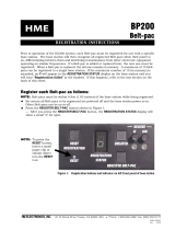
1.1. Block diagram of the E-PAC DSP software
DSP
Delay
Sine-wave
generator
Pink-noise
generator
Loudspeaker
System
equalization
Equalizer
function
(PEQ/Notch)
Limiters:
Peak
Displacment
Thermal
DACADC
Block diagram E-PAC DSP software

E-PAC Software manual
(Firmware V4.0x)
(1.0E) Page 6 of 32
2. The E-PAC operating software
2.1. E-PAC menu tree
E-PAC power amplifier controller, Menu tree
The settings for the Filter_1/_2 are dependent on the loudspeaker
configuration.

E-PAC Software manual
(Firmware V4.0x)
(1.0E) Page 7 of 32
2.2. E-PAC user interface
O
V
L
GR
I
SP
LEVEL
PUSH MENU
MUTE
POWER
[3][4]
E-PAC user interface via digital rotary
encoder LEVEL/PUSH MENU [3] in
conjunction with the LCD [4]
The LCD [4] acts as a user interface for all of the menus within the
D12/E-PAC. The cursor is controlled via the digital rotary encoder,
LEVEL/PUSH MENU [3]. In the main menu the encoder acts as a
level control. Pushing or turning the encoder gives access to
different menu levels or enables configurations or values to be
entered.
2.2.1. Conventions for the cursor and menu control
Position-Cursor
Turning the encoder moves the cursor through the menu mode.
Turning to the right moves the cursor down in the menu tree or to
the right. Turning to the left moves the cursor up in the menu tree
or to the left. Pushing the encoder activates the Edit-Cursor, except
for switching functions (e.g. "on/off"). In these instances pushing the
encoder leads directly to a change in value or condition
(toggle).
Edit-Cursor
The current set value is displayed beside the cursor and is changed
by turning the encoder. Turning to the right leads to a higher value
and to the left a lower value. A change is effective immediately
except in the functions "Speaker Selection", "Lock", "Remote",
"Device Name", "Backlight" and the "Calibrate" function within the
"Load Monitoring menu" where confirmation is required. Exit the
edit mode by pushing the encoder and return to the
Position-Cursor.
Information-Cursor
The Information-Cursor is an indicator to the fields within the menu
tree where the data displayed cannot be changed.
Menu-Change
An arrow indicates another menu level. Selecting it with the
Position-Cursor and pushing the encoder enters the corresponding
sub-menu.
Back
Exits the selected menu by moving back one level.
Scroll-Bar
Where a menu tree is longer than can be diplayed, a Scroll-Bar is
shown on the right hand side of the display for orientation.

E-PAC Software manual
(Firmware V4.0x)
(1.0E) Page 8 of 32
Other Cursors or Signs
Highlight
A highlighted field is an indication that the data displayed can be
changed in edit mode (see also Edit-Cursor above).
Pointer
In the sub-menus "Lock/Code" and "Device-Name" the highlighted
field in edit mode is clearly indicated by an arrow.
EQ-Status
In the sub-menu "Equalizer/Set" the operating status of the
respective EQ band is indicated as following
—
The respective EQ Band is switched "off" (flat)
P
The respective EQ Band is switched to "PEQ" function
N
The respective EQ Band is switched to "Notch" function

E-PAC Software manual
(Firmware V4.0x)
(1.0E) Page 9 of 32
2.3. Boot_Screen
E-PAC Boot_Screen
The boot procedure takes approximately 4 seconds during which
the device name, the manufacturers name, d&b audiotechnik AG,
and the firmware version is displayed.
The transition to the main menu is carried out automatically.
2.4. E-PAC Main_Menu
E-PAC Main_Menu
The main menu displays all of the important settings and status
informations in one view.
Filter_1
Filter_2
Remote
Level
Speaker
Device Name
EQ Master on
Delay on
Load Monitoring*
Input Monitoring
* with or without
Pilot Signal
Lock
LoImp
In the first line the loudspeaker configuration, Input and Load
Monitoring (if selected) with or without Pilot Signal are displayed.
In the second line the device name is displayed. If no device name
is entered the current firmware version of the unit is displayed.
In the third line the level and delay value are displayed. The actual
processing delay time is always shown, hence even if the delay is
turned "OFF", the basic delay time of 1 ms is displayed.
The lower line shows the "ON/OFF" status of the following
settings: Filter_1, Filter_2, Remote, Lock, LoImp, EQ.
The input sensitivity can be directly adjusted in the main menu with
the encoder (LEVEL/PUSH MENU) calibrated in 0.5 dB steps and
has a range of 63.5 dB (–57.5 dB to +6 dB). This is normally set to
0 dB.
In all other cases the encoder is used for operation within the menu
tree.
If a fault occurs (the red OVL/ Err-LED flashes), an error massage
alternating with the device name, is displayed.
In Standby-Mode, the display alternates between the device name
and Standby.

E-PAC Software manual
(Firmware V4.0x)
(1.0E) Page 10 of 32
2.5. E-PAC Settings menu
In the "Settings menu" functions can be set and further sub-menus
accessed. In the first line the dbCAN-ID (Id [n]. [n]) is displayed on
the right hand side. A detailed description of the CAN-ID is given in
the sub-menu "Remote" and the Remote section in this manual.
E-PAC Settings menu
From the main menu the "Settings menu" is entered by pressing the
encoder.
Back
Exits the sub-menu "Settings".
Setup
E-PAC Settings, Setup menu
Selecting "Setup" and pressing the encoder enters the sub-menu
"Audio Setup". In the sub-menu "Audio Setup" the following sub-
menus and functions can be accessed.
Audio Setup
E-PAC Audio Setup menu
Back
Exits the sub-menu "Audio Setup".
In the sub-menu "Audio Setup" the following sub-menus and
functions can be accessed.
Speaker
E-PAC Speaker Selection
Speaker Selection
Enables selection of individual loudspeaker configurations for the
d&b C-Series (except C3), E-Series, Q-Series and Ci-Series
loudspeakers. A linear mode is available to drive MAX/MAX12
cabinets passively.
On the right hand side the setup version of the respective
loudspeaker is displayed.
OK
If the loudspeaker configuration is edited then the confirmation
request "OK" will flash. Selecting "OK" and pressing the encoder
will confirm the configuration and exit the sub-menu "Speaker
Selection".
Cancel (
⇒
Back )
Exits the sub-menu "Speaker Selection". The previous configuration
will remain active.
Filter_1, Filter_2
E-PAC Filter_1, Filter_2
The name of the filter is clearly displayed on the left of the LCD
while the "ON" or "OFF" status is in the centre and a graphic
representation of the filters frequency response on the right.
The name and filter frequency response are dependent on the
loudspeaker configuration selected.
The display [---] indicates, that a filter is not available for the
loudspeaker type selected.
A detailed description of the filters available for each loudspeaker
is given in the respective loudspeaker data sheets .
on/off
Master filter switch. In addition the transmission function is shown
schematically on the right.

E-PAC Software manual
(Firmware V4.0x)
(1.0E) Page 11 of 32
Filter_1 Filter_2
Configuration of crossover
frequencies TOP/SUB.
e.g. CUT, 100 Hz, 140 Hz.
Depending on selected
loudspeaker set up:
Compensation towards listening
distance.
e.g. HFA, HFC.
Compensation of coupling
effects
⇒
CPL
CPL "on" = –3 dB fixed
(Lo Shelf)
Equalizer
E-PAC Equalizer
A 4 band equalizer with an optional Peak-Filter or Notch-Function
is incorporated into the signal path before the limiting circuit. The
EQ function has a Master on/off while each of the four bands can
be switched independently.
IMPORTANT!
If several EQ bands are set with a high boost in the same
frequency range, it
can cause
overflows within the DSP. These
errors are recognized internally and the E-PAC will enter mute
mode. The error message "DSP Error 16" is displayed. By changing
the centre frequency of single filters or by switching off the EQ-
Function the error can be cleared.
on/off
Master switch for the EQ function.
Set
E-PAC Equalizer, Set menu
The "Set" sub-menu gives access to the four EQ-Functions EQ_1,
EQ_2, EQ_3 and EQ_4.
Exits the sub-menu "Set".
on/off
Master switch for the EQ function.
EQ [number]
Pushing the encoder allows access to the individual EQ filters
directly, without the necessity to revert to the "Set menu".
off/PEQ/Notch
Pushing the encoder enables selection of either the "off", "PEQ"
(Peak filter) or "Notch" function.
The status of the respective EQ band is indicated as follows:
—
The respective EQ Band is switched "off" (flat)
P
The respective EQ Band is switched to "
P
EQ" function
N
The respective EQ Band is switched "
N
otch" function
The graphical representation on the display at the bottom shows
the complete transfer function of all (active) filters.

E-PAC Software manual
(Firmware V4.0x)
(1.0E) Page 12 of 32
PEQ function
E-PAC Equalizer, PEQ function
Exits the respective EQ filter.
Parametric Equalizer (PEQ)
The following parameters can be edited in "PEQ" mode:
F
Filter centre frequency adjustable from 20 Hz to 20 kHz in 3%
steps.
Q
The Q of the filter is adjustable from 0.5 ... 25 in 10% steps. In
addition, the bandwidth (BW) as a result of the Q is displayed as a
value (2.0 ... 0.04 octaves) in a non-editable field.
G
Gain, adjustable from –18dB to +6dB in 0.2dB steps.
Notch function
E-PAC Equalizer, Notch function
Exits the respective EQ filter.
The following parameters can be edited in the "Notch" mode:
F
Filter centre frequency adjustable from 20 Hz to 20 kHz in 3%
steps.
Q
The Q of the filter is adjustable from 0.5 ... 25 in 10% steps. In
addition, the bandwidth (BW) as a result of the Q is displayed as a
value (2.0 ... 0.04 octaves) in a non-editable field.
G
The parameter "Gain" (G) cannot be edited in "Notch" mode. The
centre frequency is fully attenuated (
⇒
–
∞
dB).
Delay
D12/E-PAC Delay function
on/off
Master delay switch.
[Delay-Value]
Delay time adjustable from 1 to 220 ms in steps of 0.1 ms, or a
corresponding value depending on the parameter selected.
[Parameter]
Enables selection of the delay display value in either milliseconds
[ms]; metres [m]; or feet [ft].
LoImp
E-PAC LoImp function
on/off
Master LoImp switch.
In low impedance mode the E-PAC is configured to drive low
impedance loads. Gain and the maximum output voltage is
reduced by half (–6 dB) enabling the E-PAC to drive loads at a
nominal 4-8 ohms at lower power. For example in LoImp four 16
ohms loudspeakers can be operated.
The noise floor of the amplifier is also reduced by approximately
5 dB.

E-PAC Software manual
(Firmware V4.0x)
(1.0E) Page 13 of 32
Levels
:
:
Input
Gain
Headr.
Power
[A]
[B]
E-PAC Levels monitor (bar graphs)
The following are displayed both as bar graphs and as numeric
values. Exit the "Levels-Menu" by pushing the encoder.
Gain
Input gain, the numeric value is displayed in dB. Adjustable over
the range –57.5 dB to +6 dB in 0.5 dB steps.
Input
Input signal level, the numeric value is displayed in dBu. The small
vertical line [A] represents the threshold of input level above which
the OVL LED (red) registers an overmodulation of the input. The
colon [B] provides a peak hold function.
Headr. (Headroom)
Shows the relationship between modulation and gain reduction
(GR). The small vertical line [A] indicates the gain reduction
threshold, which is 0 dB headroom/0 dB gain reduction, the colon
[B] provides a peak hold function. The GR LED (yellow) indicates a
gain reduction of more than 3 dB.
Power
The actual output power, displayed as a numeric value in watts, the
colon [B] provides a peak hold function.
Impedance Z
The impedance of the loudspeaker(s) presented to the output of the
D12/E-PAC, displayed only as a numeric value in ohms. The value
shown is dependant on the level and frequency range of the input
signal. It is a reliable indication of the output power level from 1
mW, and covers the range 0 ohms (short circuit) to 255 ohms (open
output, I = 0, Z
⇒
∞
).
Input Monitoring
According to the German Standard EN60849 "Elektroakustische
Notfallwarnsysteme" (equivalent to international standard IEC
60849 "Sound Systems for Emergency Purposes") the complete
signal chain needs to be monitored. Therfore the "Input
Monitoring" allow the detection of a incoming pilot signal in
addition to the "d&b Load Monitoring system".
A notch filter function within the "Input Monitoring menu" allows
the incoming pilot signal to be fade out of the program signal.
Input Monitoring menu
Input Monitoring
Back
Exits the sub-menu "Input Monitoring".
Mode
on/off
Switching the "Input Monitoring" On or Off.
Generate Error
on/off
An error message will be given out depending on the "on/off"
status of the "Generate Error" function.
WARNING!
In accordance with the EN 60849 (IEC 60849)
standard the "Generate Error" must be set to "on".
Detection Time
Input Monitoring, Detection Time
The maximum time the system needs to recognize malfunctions.
In accordance with the EN 60849 (IEC 60849) standard the
Detection Time can be set to a maximum of 99 seconds, or lower.

E-PAC Software manual
(Firmware V4.0x)
(1.0E) Page 14 of 32
Notch Filter
Input Monitoring, Notch Filter and
Detect monitor
A notch function is available to cut the pilot signal out of the
program signal.
Frequency
Centre frequency of the notch filter adjustable from 1 Hz to 20
kHz in 1 Hz steps.
Ferq. Fine
Fine tuning ±
1 Hz, 1/100 Hz steps
Quality
The Q of the filter is adjustable from 4 ... 42 in 1-steps. The centre
frequency is fully attenuated (
⇒
–
∞
dB).
Detect? no (yes)
The level of the external pilot signal is displayed in dBu on the right
hand side and a detection message ("yes" or "no") will given out
after "Detect?" depending on the adjusted threshold level under
"Threshold". (see "Threshold" below)
Threshold
–122 dBu to +21 dBu in 1 dB steps
Detecting (switching) threshold from measurement of the external
Pilot Signal. (see "Detect?")
Load Monitoring
Features
d&b Load Monitoring is designed to identify a possible
loudspeaker malfunction. This supervision is carried out during
regular operation, ensuring that the state of the loudspeaker
system is known at all times. d&b Load Monitoring is especially
designed to fulfil the requirements stated in the German Standard
EN60849 "Elektroakustische Notfallwarnsysteme" (equivalent to
international standard IEC 60849 "Sound Systems for Emergency
Purposes").
Function
d&b Load Monitoring checks the loudspeaker impedance
separately for both the HF and LF channels during regular
operation.
Given sufficient signal levels LM uses the music or speech Program,
however, during pauses, or when the Program Signal level is too
low for a good measurement, Pilot Signals can be used (when
selected from the menu). The frequencies of the Pilot Signals are
10 Hz and 20 kHz, which are inaudible.
These are faded in and out for a duration of approximately 2
seconds (they are not permanently on), and alternate between the
high and low frequency without causing any click or interference.
During the Calibration process, which must be carried out
immediately after the installation of the loudspeaker system, the
impedance window limits are determined. Subsequently, the
measured impedance during operation is compared against these
limits. If a sufficient number of measurements are registered outside
the impedance window limits, an impedance error is reported.
During the reproduction of the Pilot Signals the impedance is
measured within a very narrow band (only at 10 Hz and 20 kHz)
and errors can be identified with a higher accuracy than in the
broadband Program Signal operation.

E-PAC Software manual
(Firmware V4.0x)
(1.0E) Page 15 of 32
How often the Pilot Signals are switched on (period duration), how
many mis-measurements are accepted and finally the total time
until an impedance error is reported, depends on the Detection
Time, which can be adjusted in the menu.
IMPORTANT!
Notes:
The Load Monitoring is designed for the supervision of up to two
d&b loudspeakers connected in parallel (see also "Notes on non-
automated settings").
The Load Monitoring does not function when:
−
the device is muted.
−
the Pilot Signals function is turned off.
−
the signal levels are too low.
Load Monitoring menu
Load Monitoring
Back
Exits the sub-menu "Load Monitoring".
Mode
on/off
Switching the Load Monitoring On or Off.
Pilot Signals
on/off
Switching the Pilot Signals On or Off (see also sub-menu
"Frequency Generator").
IMPORTANT!
Note:
To get reliable measurements, Pilot Signals should always
be used. These are activated only when required, i.e. when the
device detects that measurements using the regular program
(music/speech) are not providing meaningful results.
Detection Time
Load Monitoring, Detection Time
The maximum time the system needs to recognize loudspeaker
malfunctions.
WARNING!
In accordance with the EN 60849 (IEC 60849)
standard the Detection Time must be set to 100
seconds, or lower.
Under unfavourable circumstances it may take substantially longer
before an error is recognized (see also "Notes on non-automated
settings").
Driver menu
Load Monitoring, Driver menu
For this example the LF Driver menu is described, the same menu is
also available for the HF Driver.
Back
Exits the respective "Driver menu".
All settings (except "Last-Err Z") are determined during the initial
adjustment. In order that the reliability of the fault detection is not
affected, these automatically determined values should only be
changed after a thorough investigation has taken place, these can
then be manually adjusted.
Definition of values:
Z-Min Program
Lower window limit of the impedance, when measured with
Program (music/speech).

E-PAC Software manual
(Firmware V4.0x)
(1.0E) Page 16 of 32
Z-Max Program
Upper window limit of the impedance, when measured with
Program (music/speech).
Z-Min Pilot
Lower window limit of the impedance, when measured with Pilot
Signal.
Z-Max Pilot
Upper window limit of the impedance, when measured with Pilot
Signal.
Test-Freq.
Test frequency for the respective driver (10 Hz LF / 20 kHz HF)
U-Threshold
Switching threshold from measurement with Pilot Signals to
measurement with Program.
Last-Err Z
Last determined impedance value that has led to a reported
impedance error.
IMPORTANT!
This value will remain unchanged even after acknowledgment of
the error message. If following the error acknowledgment a
renewed error is reported, then the previous stored value will be
overwritten.
The Calibrate menu
WARNING!
Safety precautions:
−
Nobody should ever stand directly in front of the
loudspeakers!
−
Calibration should never be carried out during a
live event.
−
Even the E-PAC is muted the calibration procedure
will start and therefore the E-PAC will be switched
to unmute.
−
After the calibration procedure the "Mode"
function within the Load Monitoring menu is set to
"off". Therefore the Load Monitoring is switched
off and the "Mode" function needs to be set "on"
again.
The Calibration menu for Load Monitoring.
Load Monitoring, Calibarte menu
Before Calibration starts, a warning dialog is displayed.
Calibration uses inaudible Pilot Signals and audible pink noise.
Calibration can also be run remotely.
Cancel (
⇒
Back )
Exits the sub-menu "Calibrate".
Calibrate
By choosing "Calibrate" the adjustment process is initiated.

E-PAC Software manual
(Firmware V4.0x)
(1.0E) Page 17 of 32
Calibrate procedure
Calibarte procedure
During Calibration the following message is displayed as shown in
the graphic opposite:
Cancel
By pushing the Encoder (LEVEL/PUSH MENU) the Calibration
process can be terminated prior to completion.
Calibarte procedure
Finished
The Calibration process lasts approximately 30 seconds and when
completed is indicated as in the graphic opposite.
Ok
By pushing the Encoder (LEVEL/PUSH MENU) the cursor will return
to the opening screen of the "Calibration" menu. Selecting
"Cancel" at this point completes the Calibration and exits the sub-
menu "Calibrate Load Monitoring".
What happens during the Calibration?
−
Load Monitoring is switched off.
−
The impedance limits are determined for measurements made
with Pilot Signals and Program during operation.
−
The minimum signal levels for the Pilot Signals are determined;
these are necessary to ensure exact measurement results.
−
The display values for the last impedance error ("Last-Err Z")
are set to 0.0 Ohms.
Possible error messages during the Calibration
Cancelled by User!
The user has interrupted the Calibration either by pushing the
Encoder or remotely.
Current too low
The level was increased to the maximum value, but the minimum
current wasn"t reached. In most cases this error message will be
displayed when a loudspeaker is not connected or there is a faulty
cable.
Current too high
The maximum current was exceeded at minimum level. In most
cases this error message will be displayed when a short circuit in
the cable or connector has occurred.
Power is off
The D12/E-PAC is in Standby mode and an adjustment is not
possible.
Remote via RIB
IMPORTANT!
Load Monitoring adjustment via RIB
For safety reasons the Calibration is locked. To enable Calibration
the following procedure should be followed:
−
Switch on Load Monitoring (set "Enable Bit")
−
Switch off Load Monitoring (reset "Enable Bit")
−
Calibrate (set "Calib-Bit")
Notes:
WARNING!
It is strongly recommended to protect the Calbration
function in ROPE by means of the Confirm dialog!

E-PAC Software manual
(Firmware V4.0x)
(1.0E) Page 18 of 32
IMPORTANT!
−
If the Calibration was successful, reset the "Calib-Bit" in the
D12/E-PAC.
−
If the Calibration was not successful, reset the "Calib-Bit" in the
D12/E-PAC again and set one or more ImpErr-Bits for 2
seconds.
−
If the user resets the "Calib-Bit" during Calibration then the
process is cancelled.
Reset of impedance errors
To reset error indications either:
−
Power Off/On at the device or remotely.
−
Switching the Load Monitoring Off/On at the device or
remotely.
−
Setting the "ImpErr-Bits" remotely.
Notes on non-automated settings
d&b Load Monitoring checks the impedance of the attached load
periodically and reports any transgression of the upper or lower
limits.
WARNING!
The three situations described below are exceptions where the
automatic Calibration settings will not suffice for the operating
conditions, and where a manual adjustment to the impedance
parameters is required.
Manual adjustment should only be undertaken after consultation
with d&b Application Support to ensure that the reliability of fault
detection is not compromised in any way.
If a malfunction creates only a minor impedance change that lies
within the limit values of the loudspeaker, the malfunction is not
displayed, this can happen when operating with Pilot Signals set to
"Off". If only a single component of the loudspeaker is
malfunctioning (e.g. a loudspeaker chassis or a component of the
crossover network), a median impedance measurement could result
when using a music Program Signal, which can lie within the normal
operating values. Using the extended limits for operation without
Pilot Signal ("Z-Min Program" and "Z-Max Program") can amplify
this effect.
If two loudspeakers are connected in parallel, the complete failure
of one driver only influences the impedance proportionately; the
resulting impedance would be roughly double. Identification of
such a defect depends on the setting of the Calibrated or adjusted
limiting values.
If the loudspeaker impedance changes to the extent that it exceeds
a limiting value, a malfunction will be displayed even though there
isn’t one. This could be caused by a very high voice coil
temperature (continuous operation at high output), or driving the
loudspeaker with narrowband signals when operating without the
Pilot Signals.

E-PAC Software manual
(Firmware V4.0x)
(1.0E) Page 19 of 32
Frequency Generator
E-PAC Frequency Generator
The frequency generator is a sweepable sine wave or pink noise
generator. The generator serves as a simple test of the functionality
of loudspeakers or for finding room resonances. The generator is in
the signal path after the delay and before the loudspeaker
equalization. The test tone will sum with any input signal present.
IMPORTANT!
NOTE:
The frequency generator is used to provide the Pilot
Signals for the "Load Monitoring" function. When using "Load
Monitoring" with Pilot Signals the frequency generator function is
not available.
Back
Exits the sub-menu "Frequency Generator".
Mode
off:
generator function is switched off.
Sin:
selects the sine-wave generator.
Pink:
selects the pink noise generator.
Level
Level of the frequency generator in dBu, covering a 63.5 dB range
from –57.5 dB to +6 dB in 0.5 dB steps. The level value
corresponds to the output level of typical signal generators needed
to produce an equal output level from the E-PAC.
Frequency
Frequency adjustable over the range 10 Hz to 20 kHz in 1 Hz
steps.
Remote
E-PAC Remote menu
Back
Exits the sub-menu "Remote".
Mode
Enables selection of the following modes for remote control:
off:
no remote control.
RIB/TI212:
remote control in accordance with TI212.
RIB:
remote control via d&b RIB/ROPE.
RIB/RS232:
remote control via RS232.
dbCAN:
remote control via dbCAN (CAN-Bus).
dbCAN Id:
Device Id (1 to 63)
Sub net (0 to 7)
Legend dbCAN Id
Setting the dbCAN identifiers [n]. [n]. The first digit represents the CAN
sub-net. Eight sub-nets can be defined (value: 0 to 7). The second digit
represents the device Id (value 1 to 63). For each sub-net 63 devices
can be defined.
Save
Selecting "Save" and pressing the encoder the dbCAN Id will be
stored (indicated with "ok" after the arrow). In case of a "System
reset" of the E-PAC the dbCAN Id will be kept.
Note:
Contrary to the other convention the remote mode is only
activated (by pushing the encoder) after leaving the edit mode.

E-PAC Software manual
(Firmware V4.0x)
(1.0E) Page 20 of 32
Lock
E-PAC Lock menu
Back
Exits the sub-menu "Lock" without entering Lock mode.
Lock now
Pushing the encoder switches the device into Lock mode and exits
the sub-menu "Lock".
Mode
There are two options to protect the device against unintentional
operation.
Press 2s
- Prevents accidental operation by locking the front
panel controls.
Password
- Password protection that prevents operation by
unauthorized persons.
Show
E-PAC Lock menu, Show
Selecting "Show" and pressing the encoder allow two different
screens to be shown after activating the "Lock now" function.
Main Screen:
switches to the "Main menu" (screen).
Levels Screen:
switches to the "Levels menu" (screen).
Password
E-PAC Password menu
Password edit mode
Enables the input of a new, or editing of an existing password
(maximum 7 characters):
−
Entering the sub-menu "Lock", will position the cursor at the
menu-point "Password".
−
Pushing the encoder enters edit mode. The pointer ( ),
indicates the entry position for new or edited characters.
Pushing the encoder enters edit mode. The pointer (
),
indicates the entry position for new or edited characters. The
selection of characters (Capital letters) is displayed in the
bottom line.
−
By turning the encoder, each alphabet character can be
highlighted. Turning left moves the cursor to the beginning of
the alphabet (
⇒
A), turning right to the end of the alphabet (
⇒
Z).
−
By pushing the encoder, the highlighted letter is entered in the
upper line and the pointer advances one place.
−
Repeat steps 1 to 4 until the complete password is entered.
−
Exit edit mode by moving the cursor to the return sign ( ) and
pushing the encoder. If an existing password is changed to a
length shorter than the previous entry, the remaining letters are
deleted automatically.
Single characters can be kept by pushing the encoder as each
character is highlighted, the pointer advancing one place after
each entry.
The editing position can be scrolled through the password
characters by pushing and turning the encoder simultaneously.
OK
Selecting "OK" and pressing the encoder will confirm the new
setting and exit the sub-menu "Password".
Cancel (
⇒
Back )
Exits the sub-menu leaving the previous password installed.
/