
A1 Mainframe
F-Series, M2, M1220
User Manual

A1 Mainframe, F-series, M2, M1220 User Manual
Version 4.0 E, 02/2001, D2100.E.04
© d&b audiotechnik 1995-2001; all rights reserved.
The information presented in this document is, to the best of our
knowledge, correct. We will however not be held responsible for
the consequences of any errors or omissions.
Technical specifications, weights and dimensions should always be
confirmed with d&b audiotechnik AG prior to inclusion in any addi-
tional documentation.
d&b audiotechnik AG
Eugen-Adolff-Strasse 134, D-71522 Backnang
Telephone +49-7191-9669-0, Fax +49-7191-95 00 00
WARNING!
CAUTION!
IMPORTANT!
References in the manual
This refers to a potentially
dangerous situation which may
lead to personal injury.
This refers to a potentially
dangerous situation which may
lead to damage to the
equipment.
This refers to a situation which
may cause the equipment to
malfunction.
Symbols on the equipment
Please refer to the information in
the operating manual.
WARNING! Dangerous voltage!

WARNING!
CAUTION!
(4.0 E) Safety precautions
Safety precautions
Before you use our products, read the manual
carefully and observe all the safety precautions.
They will protect you and help to avoid equipment
failures. Keep this manual in a safe place so that it is
available for future reference.
If you supply d&b products, please draw the
attention of your customers to these safety
guidelines. Enclose the relevant manuals with the
systems. If you require additional manuals for this
purpose, you can order them from d&b (order form
on the last page).
Information regarding use of the A1 mainframe
The mainframe complies with the electromagnetic compatibility
requirements of EN 50082-1 - residential, business and commercial
areas.
Acoustic interference and malfunctions may occur if the unit is
operated in the immediate vicinity of high-frequency transmitters
(e.g. wireless microphones, mobile phones, etc.). Damage to the
mainframe is unlikely, but cannot be excluded.
To meet the EMC requirements, use only shielded cables with
properly connected plugs for all signal terminals (INPUT, INPUT
LINK, MONO OUT).
The following information is intended to prevent fires and possible
electric shocks:
The mainframe is a protective class 1 unit. Make sure that the earth
(ground) contact is attached when the unit is in operation. A missing
earth (ground) contact may lead to dangerous voltages in the
housing and controls.
To reduce the possibility of audible hum the mainframe signal
ground (XLR pin 1) to earth (ground) connection has a high
impedance. It will prevent the unit from static charge but any
voltage applied to signal ground will pass through all connectors.
To prevent electric shock, make sure that all devices in the signal
path are grounded properly.
Never connect an amplifier output pin to any other in- or output
connector pin or earth (ground). This might damage the mainframe
or lead to electric shock.
Lay all cables to and from the unit so that they cannot be crushed
by vehicles or other equipment and that no-one can step on them.
Keep dust, moisture, water or other liquids well away from the unit.
Never operate the unit when it is open.
Always disconnect the mains power supply when replacing a
defective fuse. Only use the type of fuse listed in the specifications.

WARNING!
WARNING!
Safety precautions (4.0E)
Only carry out work specified in this manual and always disconnect
the mains power supply.
All other work should be performed by trained service staff,
especially in the following cases:
- Mains power cable or plug has been damaged
- Objects or liquids have entered the unit
- The unit is not operating normally
- The unit was dropped or the housing is damaged
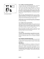
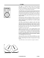
Information regarding use of loudspeakers
Never stand in the immediate vicinity of loudspeakers driven at a
high level. Professional loudspeaker systems are capable of causing
a sound pressure level detrimental to human health. Seemingly
non-critical sound levels (from approx. 95 dB SPL) can cause
hearing damage if people are exposed to it over a long period.
In order to prevent accidents when deploying loudspeakers on the
ground or when flown, please take note of the following:
When setting up the loudspeakers or loudspeaker stands, make
sure they are standing on a firm surface. If you place several
systems on top of one another, use straps to secure them against
movement.
Only use accessories which have been tested and approved by
d&b for assembly and mobile deployment. Pay attention to the
correct application and maximum loading capacity of the
accessories as specified in our Rigging Accessories Manual.
Ensure that all additional hardware, fixings and fasteners used for
installation or mobile deployment are of an appropriate size and
load safety factor. Pay attention to the manufacturers instructions
and to the relevant safety guidelines.
Regularly check the loudspeaker housings and accessories for
visible signs of wear and tear, and replace them when necessary.
Regularly check all load bearing bolts in the mounting devices.

CAUTION!
(4.0 E) Safety precautions
Only use loudspeakers in the F-Series and the M2 and M1220
monitors with the A1 mainframe fitted with the correct controller
modules. The contoller monitors cone excursion and voice coil
temperature of the drivers. When loudspeakers are operated
without the correct controller, in addition to losses in tone, there is
a risk of damage to the components. Any defects arising from
operation other than those specified in this manual will be excluded
from any warranty claims.
Loudspeakers produce a static magnetic field even if they are not
connected or are not in use. Therefore make sure when erecting
and transporting loudspeakers that they are nowhere near
equipment and objects which may be impaired or damaged by an
external magnetic field. Generally speaking, a distance of 0.5 m
(1.5 ft) from magnetic data carriers (floppy disks, audio and video
tapes, bank cards, etc.) is sufficient; a distance of more than 1 m
(3 ft) may be necessary with computer and video monitors.

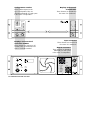
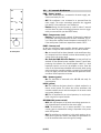
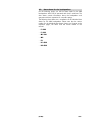
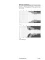
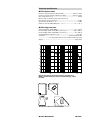
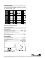
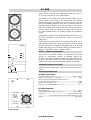
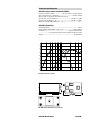
A1 mainframe front and rear views
A1
GR LO
ISP
GR HI
OV LO
OV HI
CUT
MON
LFC
MUTE
12 2 0- CO
0
-6
-12
-18
0
+3-3
dB HI dB
ID
OFF
ON
REM
PWR
TEMP
REM
PROT
LOCK
LO HI
INPUT
INPUT LINK
PUSH
REMOTE
CONTROL
FUSE T2A
220V-240V
∼
50-60 Hz
OVER
VOLTAGE
FUSE T8A FAIL
FAIL
PIN ASSIGNMENT
OUTPUT 2
OUTPUT 1
A LOW OUT +
B LOW OUT -
C SPEAKER ID
D SPEAKER ID
E SENSE DRIVE +
F SENSE DRIVE -
G HIGH OUT +
H HIGH OUT -
1220
Configuration switches
These switches depend on the
type of loudspeaker. They are
described individually for each system
in the section "Loudspeakers".
Displays and controls of
controller modules
These elements are common to all
modules. They are described in the
section "Controller modules".
Displays and controls
of mainframe
These elements are described in
the section "A1 mainframe".
Output connectors
These elements are described
individually for each system
in the section "Loudspeakers".
Input connectors
These elements are described in
the section "A1 mainframe".

(4.0 E) Contents
Contents
Safety precautions
1. Introduction................................................... 1-1
1.1. System concept.........................................................................1-1
1.2. d&b active systems design......................................................1-2
1.3. Block diagram ..........................................................................1-2
2. A1 mainframe ............................................... 2-1
2.1. Features.....................................................................................2-1
2.1.1. A1 power amplifiers ................................................................ 2-1
2.1.2. SenseDrive ................................................................................2-1
2.1.3. SpeakerID ................................................................................. 2-2
2.1.4. Fan ............................................................................................. 2-2
2.1.5. Mains overvoltage protection................................................ 2-3
2.1.6. Mains inrush current limiter....................................................2-3
2.1.7. Fuses ..........................................................................................2-3
2.1.8. Remote control & monitoring ................................................ 2-3
2.2. A1 controls & indicators..........................................................2-5
2.3. Connections .............................................................................. 2-6
2.4. Mainframe installation ............................................................ 2-7
2.5. Power consumption and power loss...................................... 2-8
2.6. Technical specifications ...........................................................2-9
3. Controller modules........................................ 3-1
3.1. Features.....................................................................................3-1
3.2. Controls & indicators............................................................... 3-2
3.3. Module exchange and replacement......................................3-3
4. Loudspeaker systems .................................... 4-1
4.1. Connections .............................................................................. 4-2
4.2. Data sheets for the loudspeakers .......................................... 4-3
F1220
F1222
M1220
M2
F2
B1-SUB
B2-SUB
5. System operation .......................................... 5-1
5.1. Setting up/stacking the loudspeakers ................................... 5-1
5.1.1. Vertical coverage ....................................................................5-1
5.1.2. Arraying mid/high cabinets ................................................... 5-1
5.1.3. Stacking subwoofers................................................................5-2
5.2. Wiring .......................................................................................5-3
5.3. Level setting for mixed systems..............................................5-4
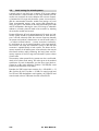
6. Troubleshooting ............................................ 6-1
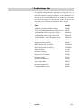
7. Publications list.............................................. 7-1
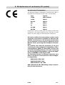
8. EU declaration of conformity (CE symbol) ..... 8-1


(4.0 E) 1-1
1. Introduction
This user manual describes the facilities, functions and operation of
d&b active controller loudspeaker systems and covers the operati-
on of the A1 mainframe, controller modules and loudspeakers used
in these systems.
d&b publishes additional application and technical information not-
es (TI). A d&b publications list and order form is appended to this
manual and we will gladly send you any of the listed publications
on request.
This user manual should provide the information you need in order
to get the best performance out of the system. If you have any
comments on the information presented, or feel that something is
inadequately explained or not covered, then please tell us using
the comments section of the publication order form.
1.1. System concept
All d&b loudspeaker systems are designed to meet the following
criteria :
- Consistent neutral sound over the full working dynamic range
- Ease of operation
- Simple set up and wiring
- Safe and reliable operation
- Compact design
In order to satisfy these demands d&b developed a complete
system concept incorporating the loudspeaker, the loudspeaker
specific control electronics (the controller) and the power amplifier.
Fundamental to the performance of the loudspeaker is the care
taken in the development of individual components resulting in well
controlled dispersion, high efficiency and excellent dynamic
response.
The controller creates the optimum mix of output level capability,
operating reliability and longevity, and pure sound quality.
Protective circuits continuously model the loudspeaker load through
simulation of cone displacement and voice coil temperature
ensuring signal level is only reduced when necessary to prevent
driver damage. No signal compression takes place within the
systems normal operating range and there is no dynamic
manipulation of system frequency response enabling most
applications and acoustic environments to require no additional
signal processing.
The power amplifier and control for each loudspeaker are housed
within the A1 and P1200A mainframes or the E-PAC power
amplifier controller. All systems are compatible, easily combined
and complementary, and can be accessed using the d&b remote
control system to allow overview and control over the most
complex applications.

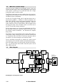
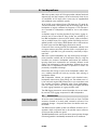
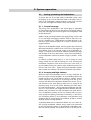
Block diagram - full range active system
Highpass
switchable
2-way box
with Speaker ID
and SenseDrive
Configuration
Level
Mute
Displacement
Temperature
Input Stage
HF-Protect
EQ VCA
Power Amplifier
Cross Over
EQ VCA
Power Amplifier
HF Level
ID
Sense
Drive
Displacement
Temperature
1-2 A1 User Manual
1.2. d&b active systems design
Their are two types of d&b active loudspeaker system - active sub-
woofers and full range, 2 way, active loudspeakers. Each type of
active system is driven by an A1 mainframe fitted with a single,
loudspeaker specific controller module.
The different loudspeaker controller modules house the signal pro-
cessing electronics, connectors, controls & indicators appropriate to
the different types of loudspeaker.
As well as the controller module, the A1 mainframe houses two se-
parate power amplifiers - a 1200 W / 4 Ohm low frequency am-
plifier and a 350 W / 4 Ohm high frequency amplifier. In the case
of the full range 1220 System, a single A1 fitted with a 1220 con-
troller module can drive two 1220 cabinets. With the higher output
full-range F2 System, each F2 cabinet needs to be driven by its
own A1/F2 controller module combination.
The full range systems can of course be supplemented with B1 or
B2 subwoofers. Each active subwoofer cabinet is driven by its own
A1/controller module combination - the mainframe HF amplifier
being unused.
The modular nature of mainframe based systems allows later re-
configuration. Simply changing the type of controller module fitted
to a mainframe alters the mode of mainframe operation without
the need for any internal changes to the mainframe itself.
The A1 mainframe incorporates an interface for remote control
and monitoring of all controller module and mainframe functions.
Active full range systems may also be used with Series 02 subwoo-
fers - e.g. the F2 System and C4-SUBs. Series 02 systems use the
d&b 1200A mainframe.
1.3. Block diagram

(4.0 E) 2-1
2. A1 mainframe
The A1 mainframe is housed in a 3 rack unit high, 353 mm (13.9")
deep, 19" rack mount enclosure. The A1 is designed to accept a sin-
gle d&b active system controller module and includes power supplies,
separate LF and HF power amplifiers, protection circuits with their in-
dicators and a remote control interface.
All mainframe facilities and functions and those of the controller
modules can be remotely interrogated and altered via the d&b
Remote Interface Bridge (RIB).
2.1. Features
2.1.1. A1 power amplifiers
The two power amplifiers fitted to the A1 can, respectively, deliver
700 W +200 W continuous sine wave power into an 8 ohm load - in-
creasing to 1200 W + 350 W continuous sine wave power into a
4 ohms load. These output ratings are valid for at least 30 minutes of
operation at an ambient temperature not exceeding 24° C.
Continuous sine wave power rating represents an extreme of operati-
on not normally encountered when reproducing typical speech and
music signals - both complex waveforms with average power levels
usually well below their peak power level. Even when driving a d&b
active system with highly compressed music (2:1 crest factor), the A1
will operate indefinitely - provided of course that the amplifier cooling
system has sufficient cool airflow.
2.1.2. SenseDrive
The accuracy of a loudspeakers signal reproduction, both level and
transient response, is influenced by dynamic damping factor - the ra-
tio of the load to source impedance.
Especially at low frequencies, the impedance of a loudspeaker will va-
ry markedly with frequency. This impedance variation will significantly
affect the system response. Whilst amplifier source impedance remains
constant the impedance of the cables and connectors will largely de-
pend upon the length and type of cable used - longer cables produce
greater signal losses.
d&b SenseDrive compensates for the electrical properties of the loud-
speaker cable. Two sense wires connect the signal from the LF driver
back to the amplifier where it is compared and corrected to compen-
sate for the cable losses. Signal reproduction is enhanced by delive-
ring the correct signal to the loudspeaker terminals irrespective of the
cable losses.
The SenseDrive technique is not used for driving the loudspeaker HF
driver since external interference from souces such as adjacent ligh-
ting wiring could interfere with the operation of the Sense-Drive cir-
cuits. The relatively high impedance of HF drivers also tends to swamp
any increase in load impedance due to longer speaker cables.
The A1 SenseDrive circuit is gain limited and whilst this imposes a cei-
ling on damping factor improvement, it guarantees stable operation
with no cable length restriction using speaker multicores such as d&b
MC8.

IMPORTANT!
2-2 A1 User Manual
2.1.3. SpeakerID
A built-in SpeakerID circuit ensures that signal can only be connec-
ted to a loudspeaker if it matches the controller module fitted to
the mainframe. When the SpeakerID circuit senses that the correct
loudspeaker is connected to the mainframe output then the internal
power amplifier outputs are fed to the mainframe speaker output
connector(s) and the green ID LED on the controller module front
panel illuminates.
With no cabinet connected, the ID LED remains unlit. If the wrong
type of cabinet is connected the ID LED will flash and the power
amplifier outputs are internally isolated from the mainframe spea-
ker output connector(s).
SpeakerID not only prevents loudspeaker damage it also prevents
hazardous voltages appearing on the exposed pins of the speaker
output connector(s).
Where a mainframe, such as the 1220 System, has two speaker
output connectors these are independently monitored and separa-
tely switched. However, to alert the user, connecting just one
wrong cabinet will mute both output connectors.
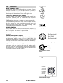
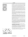
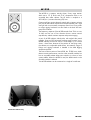
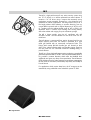
2.1.4. Fan
A fan draws in air through a filter behind the rear panel air intake.
The fan speed is governed by the temperature of the output
module heat sink and the momentary output level. This
arrangement ensures a minimum of fan noise since the fan
operates at minimum speed when power demand is low.
The level controlled fan allows greater cooling during louder
passages, thereby allowing fan speed to be reduced still further
during quiet passages preventing background noise interference.
We advise frequent cleaning of the fan filter to ensure good
airflow through the unit. If the filter is visibly dirty, then it should be
cleaned or replaced. Never operate the A1 without a filter. Dust
deposits, especially combined with damp conditions, could cause
the mainframe to malfunction.
When setting up the mainframe, do not block or cover the rear
panel air intake or the vents on the front panel of the mainframe.
See also section 2.4. (Mainframe installation).

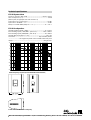
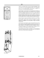
A1 mains input and fuses
∼
(4.0 E) 2-3
2.1.5. Mains overvoltage protection
To protect against mains overvoltage damage the A1 is fitted with
an efficient, self-resetting mains overvoltage protection circuit.
As soon as the mains supply voltage exceeds 265 V (115 V for the
100 V supply version) the overvoltage protection circuit responds
and isolates the mainframe power supply from the mains supply
leaving only a supervisory circuit active to monitor the mains sup-
ply voltage. The green POWER LED on the mainframe front panel
goes out and the OVER VOLTAGE LED on the mainframe rear pa-
nel comes on.
Only if the mains voltage drops below 255 V (111 V) is the mai-
nframe automatically reconnected to the mains supply and normal
operation resumed. This 10 V difference in the protection circuit
switching levels (switching hysteresis) prevents the mainframe from
cycling on and off with a fluctuating mains supply voltage.
The protection circuit will operate with any mains overvoltage up
to 400 V; allowing the A1 to survive connection across two phases
of a three phase supply.
2.1.6. Mains inrush current limiter
The mains inrush current limiter ensures a slow "start-up" for the
mainframe and allows several mainframes connected to the same
mains supply circuit to be switched on together without temporarily
overloading the supply circuit and causing a breaker to trip. The
inrush current at switch on is limited to 5 A (230 V version).
Note that repeatedly and rapidly switching a mainframe on and
off will overheat and stress the inrush current limiter circuit - a rear
panel fuse protects the circuit from damage.
2.1.7. Fuses
Two 20 mm delay fuses are fitted on the mainframe rear panel -
an 8 A fuse for the mainframe power supply and a 2 A fuse pro-
tecting the mains inrush current limiter. If either fuse should blow
then the red LED (FAIL) indicator next to the respective fuseholder
will light.
2.1.8. Remote control & monitoring
The A1 is fitted with a twin wire remote interface for various levels
of remote control and system supervision of the mainframe and its
controller module. The remote interface connection is opto-isolated
and floating.
Basic Remote
The Basic Remote is the simplest way to implement a remote control
system. A mainframe can be remotely powered on by simply ap-
plying an 18 - 28 VDC control voltage to the terminals of its re-
mote interface connector. Connecting a simple detector circuit to
the remote interface of a mainframe also allows remote warning of
a mainframe fault. Details of basic circuits for remote power cont-
rol and fault display are published in d&b technical information
bulletin TI 212.

2-4 A1 User Manual
Remote operation using the d&b Remote Interface
Bridge (RIB)
The d&b RIB is housed in a 1 RU high, 19 rack mount enclosure.
Combinations of 1 to 12 mainframes (A1 or P1200A) up to 500 m
away can be directly connected to a RIB I/O port by a twin wire
bi-directional serial link.
From the front panel of the RIB each mainframe can then be remo-
tely powered on and off and its power and error status monitored.
A group of mainframes can be switched directly by the RIB front
panel MASTER ON/OFF switch or remotely via a connection to an
opto-isolated input port on the rear panel of the RIB. Remote indi-
cation of the error status of a mainframe group can also be re-
layed by the RIB.
Computer/MIDI control
The RIB can be controlled by a computer (RS232, RS422 or MIDI in-
terface) running suitable control software or by a MIDI control de-
vice. Under computer control, the following remote control and dis-
play options become available:
Remote control
−
Power On/Off switching of mainframe
−
Level control from +0 to -63.5 dB in 0.5 dB steps.
−
MUTE switching
−
Configuration switching e.g. CUT, MON, etc.
Remote status information
−
Configuration switch status
−
Mute switch status
−
Level control setting
−
Front panel indicator status (ISP, GR, OVL etc.)
−
SPEAKER ID status
−
Protect status (DC protect, short circuit protect, thermal protect)
−
Heatsink temperature in °C
−
Available headroom (pre-limiter)
−
Gain reduction (due to limiter operation)

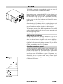
A1 front panel
OFF
ON
REM
PWR
TEMP
REM
PROT
LOCK
LO HI
(4.0 E) 2-5
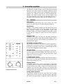
2.2. A1 controls & indicators
PWR - Power (green)
−
On
. when the mainframe is connected to the mains supply, swit-
ched on and ready for use.
−
Off
. The mainframe is not connected to or powered from the
mains supply. The mains overvoltage protection has triggered
(see above) or the mainframe is not switched on.
−
Flashes
during the initial power-up cycle for about 2 seconds
and also when the mains overvoltage protection circuit is trigge-
red by an external fault (see also PROT below).
TEMP - Temperature (red)
−
Flashes
. The mainframe has switched off because the maximum
permissable operating temperature has been exceeded. This oc-
curs if the power amplifier heatsink temperature exceeds 83° C or
if the mains power transformer temperature exceeds 120° C.
PROT - Protect (red)
As the two mainframe power amplifier channels operate indepen-
dently there are separate PROT indicators for LO and HI channel.
−
On
. An internal fault has been detected on the mainframe chan-
nel concerned and that channel has been disconnected (e.g. DC
voltage fault in the output stage).
−
On and the PWR LED also flashes
. An external fault has
switched off the affected power amplifier channel. Typical faults
producing this indication are shorted speaker cables or a load
impedance which is too low for the amplifier to drive. Once the
cause of the fault has been identified and removed, either muting
and un-muting the controller module, or powering the mainframe
off and on again, will reset the mainframe fault protection circuits
and allow normal operation to resume.
REM - Remote (green)
−
On
. The mainframe is connected to the d&b RIB and ready for
communication.
LOCK (yellow)
−
On
. The mainframe has been placed in a locked condition by a
remote control system. This means that all the mainframe and
controller module controls with the exception of the mains switch
are inactive (locked out).
−
Off
. The A1 mainframe is set to local operation, i.e. may be ope-
rated using the front panel controls.
OFF/REM/ON (power switch)
−
OFF
. With the exception of the mains overvoltage protection cir-
cuit, the mainframe is isolated from the mains supply.
−
REM
. The mainframe is set to remote operation. If no remote
control system is connected this setting is equivalent to the power
switch OFF position.
−
ON
. The mainframe is switched on. In this switch position, the re-
mote control system can monitor and display the operational sta-
tus of the mainframe but cannot change any settings.

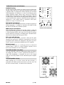
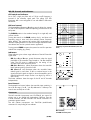
F2-CO loudspeaker output
PIN ASSIGNMENT
OUTPUT
A LOW OUT +
B LOW OUT -
C SPEAKER ID
D SPEAKER ID
E SENSE DRIVE +
F SENSE DRIVE -
G HIGH OUT +
H HIGH OUT -
F2
A1 input signal connectors
INPUT
INPUT LINK
Pin assignment for remote
control
Pin 3 (+)
Pin 1 (–)
Pin 1 (GND)
Pin 2 (pos. signal)
Pin 3 (neg. signal)
Pin assignments on P1200A signal inputs
2-6 A1 User Manual
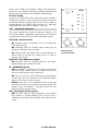
2.3. Connections
INPUT and INPUT LINK
The mainframe has a 3 pin XLR female input connector. Beneath
and wired in parallel is a 3 pin male XLR connector to provide an
input link - sometimes called a pass-through connector - used to
feed the input of the next device in the system signal chain.
Transformer balanced input (option)
To prevent system ground loops, the P1200A can be supplied with
transformer balanced inputs. The transformers used are studio
quality torroidal transformers able to handle signal levels up to
+28 dBu without degrading the systems low frequency response.
The input balancing transformer gives electrical isolation between
the source output (e.g. mixing console) and controller inputs and
therefore prevents ground loops. A 22 kohms coupling resistor
prevents electrostatic loading of the mainframe.
REMOTE CONTROL
The A1 is fitted with a two-wire serial remote control interface. The
3 pin female DIN remote control connector is located on the left of
the A1 rear panel. The connector is opto-coupled.
The remote functions are detailed in section 2.6. (Remote control &
monitoring).
OUTPUT (loudspeaker outputs)
The speaker output(s) are also located on the mainframe rear pa-
nel. Both power amplifier outputs (LF & HF), SENSE DRIVE and
SPEAKER ID connections all terminate on a single 8-pin CA-COM
connector. The CA-COM is a particularly robust and reliable bayo-
net fit (locking) connector.
Different controller modules have different output connector pin
assignments which are printed on the panel next to the connec-
tor(s). Each controller module speaker output panel is described in
the later sections of this manual along with the different active
loudspeakers and their controller modules.

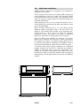
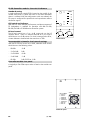
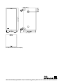
483
443
348
132
338
5
323
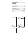
A1 enclosure dimensions
(4.0 E) 2-7
2.4. Mainframe installation
P1200A mainframe enclosures are designed to fit a standard 19"
equipment rack or cabinet.
The front panel vent slot serves as a useful handle for lifting and
moving mainframes in and out of racks. The front panel switches
are flush-fitted and the level control(s) and mainframe power
switch are recessed to protect them from accidental damage and
unintentional adjustment.
When specifying a rack, be sure to allow extra depth (10 cm is
usually sufficient) to accommodate the cables and connectors at the
rear of the mainframe(s).
When mounting mainframes into a 19" rack cabinet, provide
additional support using shelves fixed to the inner sides of the
cabinet or the mounting holes provided on the mainframe rear-
mounted rack ears - do not just rely on fixing and supporting
mainframes by their front panels. This advice is particularly
important if mainframes are being racked-up for touring use.
Since the P1200A power amplifiers can generate a lot of heat,
please ensure, whatever the mounting or racking arrangement,
that adequate cool airflow is provided to avoid a build-up of hot
air inside the rack leading to overheating. The P1200A air intake is
on the rear panel and the air outlets are set into the front panel.
To maintain good airflow through mainframes we recommend
frequent cleaning of the fan filters. If mainframes are installed in
cabinets so that direct access to the rear panel filters is not
possible, we recommend using additional fan modules with front-
mounted filters which can be easily replaced without opening the
sealed cabinets. We will gladly advise on the choice of suitable fan
modules.

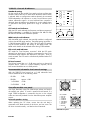
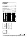
Signal
waveform
CF
P
out
[W]
P
in
[W]
P
loss
[W]
Square wave
1
2150
2900
750
Sine wave
1,4
1400
2130
730
Pink noise, com-
pressed music
3,5
200
500
300
Music with me-
dium dynamic
range
5
100
300
200
Speech, music
with wide dyna-
mic range
8
40
200
160
CF : Crest factor
P
out
: Maximum average outputpo-
wer (sum of both channels)
P
in
: Power input
P
loss
: Power loss
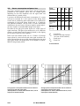
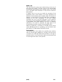
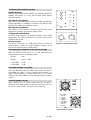
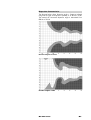
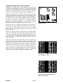
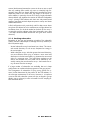
A1 Power balance
Average power consumption and loss of A1 as a factor of
output power with pink noise signal
(load impedance 4 / 8 ohms, both channels driven, sum of
output power of both channels)
Average power consumption and loss of A1 as a factor of
output power with sine wave signal
(load impedance 4 / 8 ohms, both channels driven, sum of
output power of both channels)
2000
1000
100
50
1 10 100 1000 2000
power [W]
average output power [W]
loss
consumption
2000
1000
100
50
1 10 100 1000 2000
power [W]
average output power [W]
loss
consumption
2-8 A1 User Manual
2.5. Power consumption and power loss
The power required from the mains supply and the waste heat
produced by the amplifiers power loss are variable figures
depending on the load impedance and the signal levels and
characteristics (e.g. speech, music).
In practice, the theoretical peak power consumption of a system
will only be sustained for a short period of time. Basing mains
current and air conditioning plant requirements on the peak power
consumption of the sound system would result in a generously
over-specified installation. The key factor in power consumption
calculations is the crest factor of the music signal or speech signal -
the ratio of peak to sustainable RMS voltage of the signal.
The table on the right gives power figures for various types of
signal waveforms. The figures were measured on a A1 mainframe
driving a 4 and 8 ohms load (LO and HI channel) to the clipping
point of both mainframe power amplifiers.
Power input and thermal power loss as a function of average
output power for sine wave and pink noise signal waveforms can
also be derived from the two graphs shown below (Note that pink
noise signal reaches the clipping point of the amplifiers at approx.
200 W average output power).

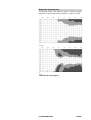
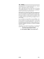
1
0.001
0.010
0.1
0.2 1
10 100
1k
2k
Low 4 ohms
Low 8 ohms
THD + Noise (%) vs Output Level (W)
High 8 ohms
(4.0 E) 2-9
2.6. Technical specifications
Nominal output power
............................................... 700 / 200 watts - 8 ohms
(THD+N < 0.1%, both channels driven)..........................1200 / 350 watts - 4 ohms
Frequency response
(1 dB)............................................................. 20 Hz - 50 Hz
measured at rated output power, both channels driven
Harmonic distortion
(THD+N)................................................ < 0.05 % / 0.03 %
from 0.1 W to rated output power, 20 Hz - 20 kHz
Intermodulation distortion
(SMPTE).................................. < 0.06 % / 0.02 %
from 0.1 W to rated output power
Residual noise
............................................................................... > 112 dB / 114 dB
below rated output power, 22 Hz - 22 kHz, unweighted, RMS
Damping factor
at loudspeaker output ................................................ > 50 / 100
20 Hz - 20 kHz, 4 ohms load
Crosstalk
............................................................................................................. < 55 dBr
Protection circuits
Mains inrush current limiter ............................................................................................ 5 A
Switch-on delay .............................................................................................................. < 2 s
Overvoltage, DC output, overtemperature and short circuits
INPUT
.........................................................................................................XLR 3-pin female
Input impedance......................................................................................................44 kohms
electronically or transformer balanced (optional)
INPUT LINK
................................................................................................XLR 3-pin male
parallel to input
C4-OUT
(B2-CO only)..............................................................................XLR 3-pin. male
balanced, output load impedance .................................................................
≥
600 ohms
OUTPUT
...........................................................................................8-pin CA-COM, male
Pin assignments depend on type of loudspeaker
General
Height x width x depth ...................... 3 rack unit x 483 mm (19") x 353 mm (13.9")
Weight with module fitted........................................................................ 22 kg (48.5 lbs)
Mains voltage (min/nominal/max) ........................ 195 /230 /265 V / 50 - 60 Hz
.................. (additionally with 115/230 V version: 98 / 115 / 132 V / 50 - 60 Hz)
............................................................ (100 V version: 85 / 100 / 115 V / 50 - 60 Hz)
Fuses ............................................................1 x 2 A Time Lag (T), 1 x 8 A Time Lag (T)
.......................................................................(115/230 V version: 2 x 8 A Time Lag (T))
....................................(100 V version: 1 x 5 A Time Lag (T), 1 x 16 A Time Lag (T))

Page is loading ...
Page is loading ...
Page is loading ...
Page is loading ...
Page is loading ...
Page is loading ...
Page is loading ...
Page is loading ...
Page is loading ...
Page is loading ...
Page is loading ...
Page is loading ...
Page is loading ...
Page is loading ...
Page is loading ...
Page is loading ...
Page is loading ...
Page is loading ...
Page is loading ...
Page is loading ...
Page is loading ...
Page is loading ...
Page is loading ...
Page is loading ...
Page is loading ...
Page is loading ...
Page is loading ...
Page is loading ...
Page is loading ...
Page is loading ...
Page is loading ...
Page is loading ...
Page is loading ...
Page is loading ...
Page is loading ...
Page is loading ...
Page is loading ...
Page is loading ...
Page is loading ...
Page is loading ...
Page is loading ...
Page is loading ...
Page is loading ...
Page is loading ...
Page is loading ...
Page is loading ...
-
 1
1
-
 2
2
-
 3
3
-
 4
4
-
 5
5
-
 6
6
-
 7
7
-
 8
8
-
 9
9
-
 10
10
-
 11
11
-
 12
12
-
 13
13
-
 14
14
-
 15
15
-
 16
16
-
 17
17
-
 18
18
-
 19
19
-
 20
20
-
 21
21
-
 22
22
-
 23
23
-
 24
24
-
 25
25
-
 26
26
-
 27
27
-
 28
28
-
 29
29
-
 30
30
-
 31
31
-
 32
32
-
 33
33
-
 34
34
-
 35
35
-
 36
36
-
 37
37
-
 38
38
-
 39
39
-
 40
40
-
 41
41
-
 42
42
-
 43
43
-
 44
44
-
 45
45
-
 46
46
-
 47
47
-
 48
48
-
 49
49
-
 50
50
-
 51
51
-
 52
52
-
 53
53
-
 54
54
-
 55
55
-
 56
56
-
 57
57
-
 58
58
-
 59
59
-
 60
60
-
 61
61
-
 62
62
-
 63
63
-
 64
64
-
 65
65
-
 66
66


Ask a question and I''ll find the answer in the document
Finding information in a document is now easier with AI
Related papers
Other documents
-
Omnitronic 80710465 Datasheet
-
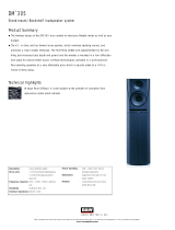 Bowers & Wilkins DM305 User manual
-
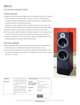 Bowers & Wilkins DM630i User manual
-
 FSP/Fortron PNA0901330 Datasheet
-
Dino-Lite MS15X Datasheet
-
Citronic CX-8088B User manual
-
Citronic CX-1608W User manual
-
Qtx QT18S User manual
-
d&b audiotechnik A1 Mainframe F-Series User manual
-
Optimus SC-630MEB-Q User manual


