Page is loading ...

Serv
ice
T
r
aining
Au
d
i
Q
7
Self-study
pr
ogr
a
mme
361

The
Audi
Q7
I
n
superior
f
a
shion,
the
A
u
di
Q7
c
ombines
spor
tin
e
ss
and
versatility
,
advanced
tec
hnolog
y
and
pr
emium-cla
ss
luxury
.
On
the
r
o
ad,
it
e
x
cel
s
wi
th
the
driving
p
e
r
f
o
r
mance
and
dy
namics
of
a
spor
ts
c
a
r
,
while
r
e
de
f
i
ning
the
possib
i
litie
s
of
its
cla
ss
of
f-r
o
ad.
A
vehicle
which
visually
display
all
its
q
u
alities
and
meets
its
pr
o
m
i
s
e
i
n
tec
hno
l
o
g
i
c
a
l
ter
m
s,
o
n
an
y
r
o
ad
an
d
under
a
n
y
conditio
ns.
A
u
di
Q7
–
the
hi
gh-perf
orman
ce
SU
V
fr
o
m
the
cr
ea
t
o
r
of
q
u
a
ttr
o.
T
h
e
very
design
of
the
Audi
Q
7
sets
new
standards
.
Char
acteristic
of
the
typic
a
l
A
u
di
dynamism
ar
e
the
swoo
pi
ng
cu
rve
o
f
t
h
e
r
o
of
line
and
the
dis
t
inc
t
iv
e
r
e
la
tionship
betw
ee
n
the
high
wa
ist
l
ine
and
na
rr
ow
window
a
r
ea.
T
h
e
dynamic
sweep
of
the
fr
ont
se
ction
an
d
the
powerf
ul
r
e
ar
with
the
sharply
sloping
D
-
pillars
pr
ovide
a
c
o
up
e-
li
ke
pr
o
f
i
l
e.
Eq
ua
lly
c
h
a
r
ac
teri
stic
elem
ents
of
the
cur
r
ent
A
u
di
sty
l
ing
ar
e
the
shoulder
lin
e
an
d
dyna
mic
lin
e
which
de
f
i
ne
th
e
side
section
.
361_0
00
T
a
king
the
le
ad:
With
de
sig
n
&
per
f
orma
nce

Co
n
t
e
n
t
s
Intr
oduction
.
.
.
.
.
.
.
.
.
.
.
.
.
.
.
.
.
.
.
.
.
.
.
.
.
.
.
.
.
.
.
.
.
.
.
.
.
.
4
Body
.
.
.
.
.
.
.
.
.
.
.
.
.
.
.
.
.
.
.
.
.
.
.
.
.
.
.
.
.
.
.
.
.
.
.
.
.
.
.
.
.
.
.
.
8
P
a
ssenger
protection
.
.
.
.
.
.
.
.
.
.
.
.
.
.
.
.
.
.
.
.
.
.
.
.
.
.
.
.
.
12
Engine
.
.
.
.
.
.
.
.
.
.
.
.
.
.
.
.
.
.
.
.
.
.
.
.
.
.
.
.
.
.
.
.
.
.
.
.
.
.
.
.
.
.
34
Running
gear
.
.
.
.
.
.
.
.
.
.
.
.
.
.
.
.
.
.
.
.
.
.
.
.
.
.
.
.
.
.
.
.
.
.
.
.
44
Electric
al
system
.
.
.
.
.
.
.
.
.
.
.
.
.
.
.
.
.
.
.
.
.
.
.
.
.
.
.
.
.
.
.
.
.
50
Air
conditioning
system
.
.
.
.
.
.
.
.
.
.
.
.
.
.
.
.
.
.
.
.
.
.
.
.
.
.
54
Inf
o
tainment
.
.
.
.
.
.
.
.
.
.
.
.
.
.
.
.
.
.
.
.
.
.
.
.
.
.
.
.
.
.
.
.
.
.
.
.
68
T
h
e
s
e
lf-s
tudy
pr
og
r
a
mme
pr
ov
ides
ba
sic
i
n
f
o
r
m
at
ion
on
t
h
e
desig
n
and
fu
nctio
n
of
new
vehi
c
l
e
model
s
,
new
v
e
h
i
cle
compon
ents
or
new
tec
h
nologi
es.
T
h
e
s
e
lf
-
s
tu
d
y
p
r
og
r
a
mm
e
is
no
t
in
te
n
d
e
d
a
s
a
w
o
r
k
s
h
o
p
m
a
nu
al
.
The
spe
cifi
e
d
v
a
lues
on
ly
s
erve
f
o
r
bet
t
er
un
d
e
r
s
t
andin
g
a
n
d
r
e
la
t
e
t
o
th
e
so
ftwa
r
e
ver
s
io
ns
appli
c
ab
le
at
t
h
e
ti
m
e
th
e
SS
P
w
a
s
co
m
pil
e
d
.
F
or
m
a
in
tenan
c
e
and
r
e
pa
ir
oper
ations
it
i
s
ess
e
ntia
l
that
you
r
e
f
e
r
t
o
t
h
e
cu
rr
ent
tec
h
n
i
c
a
l
li
ter
a
t
u
r
e
.
Not
e
No
te

Intr
oduction
In
a
nutshell
Some
A
u
di
Q7
dimension
s
.
361
_
045
361
_
046
5-
s
e
at
er
6/
7
-se
at
e
r
A
d
miss
ibl
e
t
o
ta
l
weigh
t
in
k
g
4.2l
FSI
3.0l
TDI
U
n
la
den
weigh
t
with
ou
t
dr
ive
r
in
kg
4.2l
FSI
3.0l
TDI
D
r
ag
co
ef
fi
cien
t
C
w
0.37
2895
2950
2240
2295
3065
3120
2270
2325
T
a
nk
c
a
pa
ci
ty
in
lit
r
e
s
100
T
r
a
ile
r
we
ight
,
br
a
k
ed
(on
12
%
uph
ill
gr
ad
ien
t
)
in
k
g
3500 3200
N
o
se
we
ight
in
kg
140 130
C
o
mb
in
at
ion
weigh
t
(1
2
%)
i
n
k
g
4.2l
FSI
3.0l
TDI
A
d
miss
ibl
e
r
oo
f
loa
d
in
k
g
100
6495
6550
6365
6420
4

Int
e
ri
or
di
mensi
o
n
s
361
_
103
Lu
gg
age
com
p
artmen
t
v
o
l
u
me
775
l
330
l
36
1_105
361
_
104
2035
l
361_10
6
5

Intr
oduction
Body
T
h
e
body
of
the
A
u
di
Q7
ha
s
been
newly
d
e
veloped
by
A
u
di
an
d
is
not
ba
sed
on
a
pr
edecessor
SUV
model.
Durin
g
the
deve
lopment
p
r
oce
ss,
the
most
signif
icant
pr
oper
ti
es
and
c
h
a
r
acteristi
c
val
u
es
w
e
r
e
initia
lly
def
i
n
e
d.
F
o
r
e
x
ample:
●
body
weight
●
t
ors
io
na
l
an
d
b
e
nd
i
ng
v
a
lu
e
s
●
cr
a
s
h
perf
orman
c
e
●
sc
h
e
duled
development
time
●
sco
p
e
of
si
mul
a
t
i
o
n
a
nd
pr
otot
ype
devel
opmen
t
●
p
l
a
n
ne
d
in
s
u
ra
nc
e
c
a
teg
ory
Signific
an
t
f
ea
t
ur
es
of
the
A
u
di
Q7
b
o
dy
shell
ar
e a
hig
h
o
v
eral
l
rig
i
dity
a
s
well
a
s
o
p
tim
i
sed
l
o
c
a
l
ben
d
in
g
an
d
t
o
rsion
a
l
va
lues
at
the
body
n
o
des
an
d
f
o
rce
application
a
r
eas.
Bodys
hell
361
_
055
Th
e
d
e
v
e
l
o
pm
e
n
t
●
of
an
open
sky
system,
●
an
optio
n
al
third
se
at
r
o
w
,
●
a
tailgate
with
integr
ate
d
r
e
ar
lights,
which
wr
ap
s
ar
ou
nd
to
the
r
e
ar
side
pa
n
e
l,
wer
e
fu
r
t
her
i
mpo
r
t
an
t
f
e
atu
r
es.
T
h
e
f
o
cus
wa
s
on
combining
these
elemen
ts
with
the
typic
a
l
Audi
high
q
u
ality
e
x
pr
essed,
f
o
r
instan
ce,
in
the
dimens
ional
accu
r
a
cy
o
f
the
body
par
t
s,
the
nar
r
o
w
gap
widths
an
d
sur
f
ac
e
f
i
nish.
T
h
e
sel
f
-su
ppor
t
i
ng
,
l
i
ghtwei
ght
ste
e
l
body
o
f
the
A
u
di
Q7
is
buil
t
in
f
o
ur
bo
dysh
el
l
ver
s
ions:
●
Nor
m
al
r
oo
f
●
N
o
r
m
a
l
ro
o
f
w
i
t
h
t
h
re
e
s
ea
t
ro
w
s
●
P
a
nor
a
ma
r
o
of
(open
sky
system)
●
P
a
nor
a
ma
r
o
of
(open
sky
system)
with
thr
ee
seat
ro
w
s
T
h
e
A
u
di
Q7
with
thr
ee
seat
r
o
ws
is
eq
uipp
e
d
with
a
n
additiona
l
cr
oss-
piec
e
in
the
sp
a
r
e
wh
ee
l
well
ar
ea
f
o
r
attac
hment
of
the
seat
belts
.
On
the
ve
rsions
with
the
panor
a
ma
r
o
of,
the
cr
oss-
piec
es
a
t
the
B
and
C-
pi
ll
ar
s
ar
e
dispensed
with.
T
heir
function
is
fu
lf
ill
e
d
by
th
e
open
sky
mo
dule.
6

Joining
tec
hniq
ues
I
n
order
t
o
meet
the
high
demand
s
with
r
e
gard
t
o
body
rigidity
,
cr
a
s
h
saf
e
ty
and
optimised
pr
oduction
pr
ocesses,
the
f
o
llowing
joining
tec
h
niq
u
es
a
r
e
emplo
y
ed
on
the
A
u
di
Q7:
–
S
p
o
t
w
e
l
d
i
ng
–
S
p
o
t
w
e
l
d
b
o
nd
i
ng
–
M
A
G
w
e
l
d
i
ng
–
L
a
s
er
soldering
–
P
la
smatr
o
n
soldering
T
h
e
joining
tec
h
niq
u
e
most
fr
eq
uently
emplo
y
ed
f
o
r
ar
ea
s
subject
t
o
high
load
s
is
spot
weld
bonding
using
a
structur
al
adhesive.
T
h
e
bonded
jo
ints,
w
i
th
a
length
o
f
79815
mm,
co
mprise
5403
spot
welds.
T
h
e
t
o
tal
length
o
f
the
la
ser
-
solder
ed
join
ts
(
s
eamless
joints
betwee
n
r
o
of
and
si
d
e
fr
ame)
amou
nts
t
o
4420
mm.
As
with
the
A
u
di
A3
Spo
r
tbac
k
and
the
A
u
di
A6
Avant
'05,
the
side
pa
nel
a
nd
the
r
a
in
c
h
a
n
nel
ar
e
joined
using
pla
s
matr
on
solde
r
ing.
Like
la
ser
soldering,
this
te
c
h
niq
u
e
ensur
e
s
a
h
i
gh-q
uality
and
a
vir
t
ually
invisible
seam.
T
h
e
length
of
the
le
f
t
and
right
joints
amo
u
nts
t
o
1438
mm.
T
h
e
length
of
the
MA
G
welded
jo
ints,
u
s
ed
in
a
r
ea
s
which
a
r
e
ina
c
cessib
l
e
using
welding
t
o
ngs,
amo
u
nts
t
o
15272
mm.
Adhesive
Pla
s
matr
o
n
solde
r
ing
La
ser
soldering
Spot
welding
(not
sh
own)
MA
G
welding
(not
shown)
361
_
057
7

Body
Mat
e
rial
s
I
n
addition
t
o
the
jo
in
ing
tec
h
niq
u
es
e
mp
l
o
y
ed,
selection
of
th
e
cor
r
ect
materials
is
vital
f
o
r
ac
hieving
both
cr
a
s
h
saf
e
ty
and
body
rigidity
.
D
e
pending
on
l
o
a
d
ing
a
nd
weig
ht,
the
most
suita
b
le
materi
al
is
deter
mined
f
o
r
eac
h
component.
T
h
e
pr
opor
tions
of
the
individua
l
materi
al
s
used
ar
e
as
fo
ll
o
w
s
:
–
S
tandard
steels
36
%
–
H
igh-str
e
ngth
steels
26
%
–
H
igher
-
str
e
ngth
an
d
super
high-strength
steels
32
%
–
A
l
u
m
i
n
i
u
m
6
%
T
h
e
wing
panel
s
,
b
o
nne
t
a
nd
tailgate
ar
e
made
of
a
l
uminium,
making
them
some
22
kilogr
ammes
lighter
than
th
e
i
r
stee
l
co
unterpar
ts.
T
h
e
weight
wa
s
fur
t
her
r
e
duced
thr
o
ugh
the
use
of
various
semi-
f
i
nished
pr
oducts*.
With
ta
ilor
ed
r
o
lled
b
l
an
ks,
f
o
r
e
x
ample
,
the
wall
thic
kne
sses
c
a
n
be
adapted
t
o
withstand
dif
f
ering
component
load
ing
.
T
h
e
r
e
inf
orcements
f
o
r
the
r
e
ar
longitudinal
members
and
the
f
l
oo
r
cover
pa
nel
a
r
e
made
fr
om
tai
l
or
ed
r
o
ll
ed
bla
n
ks.
*
Semi-f
inished
pr
oducts:
P
r
e-p
r
ocessed
materials
f
o
r
the
manuf
a
ctur
e
of
par
t
s
and
componen
ts
T
h
e
sill
tube
consists
of
a
r
o
lled
section
bec
a
use
t
h
e
manuf
a
ctu
r
ing
t
o
ler
a
nces
a
r
e
lo
wer
in
this
c
a
se
than
f
o
r
an
e
x
truded
tu
be
,
enabl
i
ng
smal
le
r
wal
l
thic
knesses.
In
order
t
o
me
et
pedestrian
pr
otection
r
e
q
u
ir
ements,
pla
s
tic
par
t
s
ar
e
used
in
the
ple
num
c
h
amber
/
bulk
head
ar
ea
.
8

Stan
dard
ste
e
ls
High
str
e
ng
th
ste
e
ls
Hi
gh
e
r
-str
en
gth
a
nd
super
hig
h
-str
en
gth
s
t
eels
Al
u
m
in
iu
m
361_0
56
9

Body
Se
at
concept
T
h
e
A
u
d
i
Q7
seats
up
t
o
s
e
ven
occ
u
pan
t
s.
As
standard,
th
e
A
u
di
Q7
is
eq
uipped
w
i
th
f
i
ve
seats.
T
h
e
A
u
d
i
Q7
c
a
n
optio
n
ally
be
f
i
tted
with
e
l
ectric
al
ly-
a
djustable
s
e
ats
f
o
r
the
driver
a
nd
fr
ont
pa
ssen
g
er
.
A
memory
function
is
also
available
f
o
r
the
fr
o
n
t
seats
.
T
h
e
bac
k
r
e
sts
of
the
driver
and
fr
on
t
pa
ss
enger
seats
hav
e
been
er
g
o
n
o
mic
a
lly
designe
d
suc
h
a
s
t
o
r
e
d
u
ce
t
o
distance
between
the
occ
u
pan
t
's
head
a
nd
the
head
re
st
ra
i
n
t
.
T
h
e
h
ea
d
re
s
t
m
u
s
t
b
e a
d
j
u
s
t
ed
c
o
rr
e
c
t
l
y
f
o
r
this
purpose
.
T
h
e
seats
in
th
e
sec
o
nd
seat
r
o
w
c
a
n
be
individu
al
ly
a
djusted
long
itu
dinally
a
nd
of
f
e
r
occupa
nt
s
the
most
gener
o
us
leg
r
o
om
in
th
is
vehicle
cla
ss.
Wher
e
the
Audi
Q7
is
eq
uipped
with
a
third
seat
r
o
w
,
th
e
second
sea
t
r
o
w
f
ea
t
ur
es
an
easy-e
ntry
func
tion
a
nd
l
o
ng
i
t
udi
n
a
l
seat
adju
stment.
In
the
6-
seater
eq
u
i
pment
ver
s
i
o
n,
co
mf
or
t
seats
ar
e
o
p
ti
o
n
al
l
y
a
v
aila
ble
f
o
r
the
sec
o
nd
seat
r
o
w
.
A
u
di
Q7
w
i
th
sev
e
n
se
a
t
s
Audi
Q7
with
s
i
x
se
ats
361
_
050
Audi
Q7
wi
th
five
se
ats
36
1_052
Note
Plea
se
r
e
f
e
r
t
o
the
owner's
ma
nua
l
f
o
r
inf
orma
t
io
n
on
o
p
er
ati
o
n
o
f
the
vehicle
seats.
361
_
049
10

T
h
e
head
r
e
str
a
ints
of
the
sec
o
nd
seat
r
o
w
do
not
pr
eve
n
t
the
bac
k
r
e
sts
fr
om
f
o
ldin
g.
When
the
hea
d
re
st
ra
i
n
t
s
o
f
t
h
e
s
e
c
o
nd
s
ea
t
r
o
w
a
r
e
l
o
w
e
re
d
,
t
h
e
bac
k
r
e
sts
do
not
fully
r
e
ac
h
the
load
f
l
oor
position.
When
f
o
lding
down
the
bac
k
r
e
sts
of
the
third
seat
ro
w
,
t
h
e
h
ea
d
re
s
t
ra
i
n
t
s
l
o
w
e
r
a
u
t
o
m
a
t
i
c
a
ll
y
,
m
a
k
i
ng
it
ea
sier
t
o
f
o
ld
down
the
bac
k
r
e
sts.
I
f
the
seats
in
the
second
and
third
seat
r
o
ad
s
ar
e
u
n
o
cc
u
p
i
e
d
,
t
h
e
h
ea
d
re
s
t
ra
i
n
t
s
c
a
n
b
e
l
o
w
e
re
d
b
y
ha
nd
in
o
r
der
to
impr
ove
r
ea
r
wa
rd
visi
bili
ty
.
T
h
e easy-e
ntry
func
tion
on
the
second
seat
r
o
w
is
o
p
erated
vi
a a
l
e
ver
ne
xt
t
o
the
head
r
e
str
a
i
n
t.
T
h
e
ba
c
k
r
e
st
f
o
ld
s
f
o
r
w
a
r
d
s
t
o
a
cer
t
ai
n
an
gl
e.
T
h
e
seat
ba
se
also
moves
in
the
dir
e
ction
of
tr
avel.
T
h
e easy-
en
try
fun
c
tion
ena
b
les
the
occ
u
pan
t
s
t
o
enter
and
e
x
it
the
thir
d
seat
r
o
w
.
361
_
051
Attac
hment
of
the
seat
belts
t
o
the
seats
of
the
third
sea
t
r
o
w
is
ac
hieve
d
vi
a
addi
ti
o
n
al
bel
t
bu
c
k
le
s.
T
h
e
advantage
is
that
the
seatbelts
c
a
n
b
e
r
e
moved
fr
om
the
seats
a
s
r
e
q
u
ir
ed.
T
h
e
seat
belts
ar
e
r
e
t
r
acted
and
the
latch
plates
c
a
n
be
inser
t
ed
in
th
e
D-pillar
tr
im.
I
n
this
manner
,
the
seat
belts
ar
e
pr
otected
ag
ainst
damag
e
during
loading
of
the
lug
g
ag
e
c
ompar
tmen
t
when
the
ba
c
k
r
e
sts
ar
e
f
o
l
d
ed
down
.
T
h
e
c
e
ntr
a
l
belt
bu
ckles
ar
e a
tta
c
h
ed
t
o
the
v
e
hicle
f
l
oor
.
P
e
rsons
above
a
height
of
160
cm
ar
e
pr
ohibited
fr
om
being
sea
t
ed
in
the
third
seat
r
o
w
.
361
_
044
11

P
a
ssenger
pr
otection
P
a
ssenger
pr
otection
in
the
A
udi
Q7
Owing
t
o
its
wide
r
a
ng
e
of
use,
the
A
u
di
Q7
r
e
pr
esen
ted
a
spec
ia
l
c
h
a
l
lenge
f
o
r
the
development
tea
m
:
A
high
degr
ee
of
pa
sse
nger
p
r
otec
tion
du
ring
bo
th
on-
r
oa
d
a
nd
of
f-r
o
ad
oper
ati
o
n.
I
n
meeting
these
r
e
q
u
ir
eme
n
ts,
t
h
e
A
u
di
Q
7
f
i
ts
sea
m
less
ly
int
o
the
hig
h
sa
f
e
ty
level
of
the
cur
r
e
nt
A
u
di
mode
l
ra
ng
e
.
T
h
e
pa
ssen
g
er
pr
otection
system
of
the
A
u
d
i
Q7
comprises
th
e
f
o
llowing
c
o
mponents
and
systems:
–
A
i
r
b
a
g
c
o
n
t
r
o
l
u
n
i
t
–
D
river
and
fr
ont
passeng
er
ai
r
b
ag,
dua
l
sta
g
e
–
F
r
o
n
t
s
i
d
e a
i
r
b
a
g
s
–
S
ideg
ua
r
d
s
(c
ur
t
a
in
a
i
r
b
ag
s)
–
C
r
a
sh
sen
s
ors
f
o
r
f
r
ont
airbag,
the
so-c
alled
upf
r
o
n
t
sensors
f
o
r
fr
ontal
imp
a
ct
detection
–
C
r
a
sh
sen
s
ors
at
the
B-pillars
f
o
r
side
impact
detection
–
C
r
a
sh
sen
s
ors
at
the
C-pillars
f
o
r
side
impact
detection
–
F
r
o
nt
bel
t
ten
s
ioners
–
B
a
ttery
isola
t
io
n
ig
niter
–
S
w
i
tc
h
in
f
r
o
n
t-seat
belt
buc
k
les
–
S
eat
occ
u
pied
sensor
in
f
r
ont
pa
ssen
g
er
seat
Si
de
a
i
r
b
ag
s
f
o
r
the
seco
nd
sea
t
r
o
w
an
d
a
k
e
y
o
p
er
ate
d
switch
f
o
r
deactivation
of
the
fr
ont
pa
ss
enger
airbag
with
the
cor
r
e
spo
n
ding
warning
lamp
ar
e
al
so
ava
i
la
ble
a
s
opti
on
al
e
q
u
i
pm
e
n
t.
Owing
t
o
the
va
rious
r
e
q
u
ir
ements
and
statut
ory
r
e
gu
la
tions
pla
c
ed
upon
vehic
l
e
manuf
a
ctur
ers
by
the
markets,
th
e
eq
uipment
versions
ma
y
va
ry
,
pa
r
t
icularly
with
r
e
gard
t
o
the
US
market.
Ke
y
E24
D
river
side
belt
switch
E25
F
r
o
nt
p
a
ssenge
r
side
belt
switch
E22
4
K
e
y
oper
ated
switch
t
o
d
e
activate
fr
ont
pa
sse
nger
side
airbag
G128
Seat
occupied
sen
s
or
,
fr
ont
passenger
side
G179
Side
airb
ag
cr
a
s
h
sensor
on
driver
side
(B-pillar)
G180
Side
airb
ag
cr
a
s
h
sensor
on
fr
on
t
pa
ssen
g
er
side
(B-pillar)
G256
Re
ar
side
a
i
rb
ag
c
r
a
s
h
sensor
on
dr
iver
side
(C-pi
lla
r)
G257
Rear
side
airb
ag
cr
a
s
h
sensor
on
pa
ssenge
r
side
(C-pillar)
12

361
_
001
G28
3
Fr
on
t
airb
ag
c
r
a
s
h
se
n
s
or
f
o
r
drive
r
side
(fr
o
nt
end,
lef
t
)
G28
4
Fr
ont
airbag
cr
a
s
h
sensor
f
o
r
f
r
ont
passenger
side
(fr
o
n
t
en
d,
right)
J234
Airbag
contr
o
l
unit
J285
C
o
ntr
o
l
unit
in
dash
pa
nel
i
n
ser
t
J393
C
o
nven
ien
c
e
system
c
e
ntr
a
l
contr
o
l
un
it
J533
D
a
ta
bus
diagnostic
in
te
r
f
ac
e
(g
ate
w
a
y
)
J623
Engine
co
ntr
o
l
u
n
it
K1
9
S
ea
t
be
lt
war
n
in
g
syst
em
warning
lamp
K7
5
A
irbag
wa
rning
la
mp
K1
45
Fr
ont
pa
ss
enger
sid
e
airbag
de
activated
wa
rn
in
g
la
mp
(P
A
SSE
NG
ER
AI
RBA
G
O
FF)
N95
D
river
side
a
i
rba
g
igniter
N
250
Dr
i
v
er
si
de
ai
r
b
ag
i
g
ni
ter
2
N131
Fr
ont
p
a
ssenge
r
side
airbag
igniter
1
N132
Fr
ont
p
a
ssenge
r
side
airbag
igniter
2
N153
Driver
sea
t
b
e
l
t
tensioner
ig
niter
1
N154
Fr
ont
p
a
ssenge
r
seat
bel
t
ten
s
ioner
ig
niter
1
N199
Side
airb
ag
igniter
on
driver
side
N200
Side
a
i
rb
ag
igniter
on
fr
on
t
pa
ssen
g
er
s
i
de
N
251
Dr
i
v
er
si
de
cu
r
t
ai
n
ai
r
b
ag
i
g
ni
ter
N252
Fr
ont
p
a
ssenge
r
side
c
u
r
t
ain
airbag
ign
i
ter
N253
Batter
y
iso
l
at
ion
igniter
T16
C
onn
e
ct
or
,
16-pin
(diag
nostic
connection)
13

P
a
ssenger
pr
otection
Airbag
contro
l
unit
J234
T
h
e
purpose
of
the
electronics
integr
a
t
ed
in
the
airbag
contr
o
l
unit
is
t
o
detec
t
vehicl
e
decel
e
r
a
tion
or
a
ccel
e
r
a
tion
and
t
o
e
v
al
ua
te
it
so
a
s
t
o
detect
a
vehic
l
e
impact.
In
order
t
o
dete
ct
ve
h
i
cl
e
decel
e
r
a
tion
or
a
ccel
e
r
a
tion
during
a
n
imp
a
ct,
e
x
tern
al
sensors
a
r
e
use
d
in
addition
t
o
the
sensor
s
instal
led
inside
the
contr
o
l
unit.
T
h
e
electronics
in
the
contr
o
l
un
it
detect
a
cr
a
s
h
ba
se
d
a
l
one
on
the
in
f
o
rmation
r
e
ceived
fr
om
the
sen
s
ors.
O
nly
once
all
the
sensor
inf
o
rmation
ha
s
b
e
en
e
v
alu
a
ted
by
the
co
ntr
o
l
u
n
it
elec
tr
onics
c
a
n
the
electronics
decide
wh
e
n
and
which
saf
e
ty
compo
n
ents
shou
ld
be
activated.
T
h
e
ai
r
b
ag
co
ntr
o
l
u
n
i
t
i
s
abl
e
t
o
detec
t
fr
o
n
tal
,
side
a
nd
r
e
ar
i
m
pac
t
s.
A
fur
t
her
ta
sk
of
the
airbag
contr
o
l
unit
is
t
o
activate
the
r
e
levant
r
e
str
a
int
sys
t
ems
(
b
e
l
t
tension
e
rs
or
belt
ten
s
io
ner
s
and
ai
r
b
ag)
depen
d
in
g
o
n
the
t
y
pe
a
nd
se
veri
ty
of
the
impact
a
s
well
a
s
signalling
the
cr
a
s
h
t
o
other
vehicle
systems.
T
h
e
airbag
electronics
have
the
f
o
llowing
main
ta
sks:
–
C
ra
s
h
d
e
t
e
ct
i
o
n
(
f
ro
n
t
,
s
i
d
e
,
re
a
r
)
–
D
ef
in
ed
trig
gering
of
the
belt
tensione
rs,
airbags
and
battery
isolation
igniter
–
D
ef
in
ed
trig
ge
ring
of
the
second
fr
ont
a
i
rbag
stage
–
E
va
lua
t
io
n
of
al
l
i
np
u
t
i
n
f
o
rm
a
t
ion
–
P
erma
nent
mon
i
t
o
ring
of
the
comp
l
e
te
airbag
system
–
I
ndepende
nt
power
supply
via
a
c
a
pacit
o
r
f
o
r
a
def
i
ned
time
(appr
o
x
.
150
ms)
–
F
au
lt
di
spla
y
vi
a a
f
a
i
l
ur
e
war
n
i
ng
l
a
mp
–
S
t
o
r
a
g
e
of
f
a
ult
and
cr
a
s
h
i
n
f
orma
t
ion
–
C
ommunic
a
tion
o
f
a
cr
a
s
h
t
o
the
other
system
components
via
the
drive
CAN
or
discr
e
te
cr
a
s
h
output
(conventional
w
i
ring)
–
A
ctiva
t
ion
o
f
sea
t
bel
t
wa
rning
system
361
_
007
F
o
r
inf
orma
t
io
n
on
which
components
must
be
r
e
pla
c
ed
f
o
ll
ow
in
g
an
a
cc
i
de
n
t
,
pl
ea
se
r
e
f
e
r
to
the
app
l
ic
a
b
le
W
o
r
k
sho
p
Man
u
a
l
i
n
E
L
SA
.
An
ai
r
b
ag
co
ntr
o
l
u
n
it
c
a
n
o
nly
be
r
e
pl
aced
wi
th
the
ai
d
o
f
an
on
li
ne-
c
apabl
e
V
A
S
5051
or
V
A
S
5052
.
T
h
e
guided
f
a
ult-f
i
nding
or
gui
d
ed
functi
on
appli
c
ati
o
ns
must
be
u
s
ed
f
o
r
th
is
pur
p
ose.
T
h
e
airbag
contr
o
l
unit
must
be
c
oded
and
adapted
t
o
th
e
r
e
levant
vehic
l
e.
I
f
cod
i
ng
or
adaption
is
not
per
f
ormed
cor
r
ectly
,
this
ma
y
r
e
sul
t
in
mal
f
unctions
in
oth
e
r
vehicle
syste
m
s,
e.g.
the
ES
P
.
14

Da
t
a
ex
ch
a
n
g
e
T
h
e
airbag
contr
o
l
unit
is
connected
t
o
the
drive
CAN.
T
h
e a
i
rba
g
contr
o
l
unit
tr
a
nsmits
the
f
o
ll
ow
ing
inf
orma
t
io
n
via
the
dr
ive
CA
N:
–
A
ctiva
t
ion
o
f
w
a
rning
l
a
mp
K7
5
–
A
ctiva
t
ion
o
f
sea
t
bel
t
wa
rning
system
–
D
iagnostic
data
–
C
r
a
sh
sign
al
–
C
r
a
sh
inf
orma
t
ion
f
o
r
the
con
t
r
o
l
eleme
n
t
tes
t
–
E
S
P
d
a
t
a
–
F
r
o
nt
passeng
er
a
i
rbag
a
c
ti
vated/deac
tivated
status
(
d
isplay
in
dash
panel
inser
t
)
T
h
e a
i
rba
g
contr
o
l
unit
eva
l
u
a
tes
the
f
o
ll
o
w
ing
inf
o
r
m
atio
n
fr
om
the
da
ta
bus:
–
D
imm
i
ng
f
o
r
the
fr
ont
passenger
side
airbag
de
activated
warning
lamp
(P
a
ssenger
Airbag
O
f
f)
T
h
e
inf
o
r
m
atio
n
tha
t
a
cr
a
s
h
ha
s
o
c
cu
rr
ed
is
used
by
ot
her
c
o
n
t
r
o
l
un
its
in
or
der
to
u
nloc
k
a
lo
c
k
ed
c
e
n
t
r
a
l
loc
k
ing
system,
cut
of
f
the
fuel
supply
,
activate
the
hazard
warning
ligh
ts
etc.
Ai
rba
g
w
arnin
g
l
a
mp
K75
Activation
of
the
airbag
warning
lamp,
which
is
lo
c
a
ted
in
the
dash
panel
inser
t
J285
,
is
per
f
o
r
med
vi
a
the
CAN
bus.
I
n
the
absen
c
e
of
a
data
messa
ge
fr
om
the
airb
a
g
contr
o
l
un
it,
the
wa
rn
in
g
lamp
is
switch
ed
on
au
t
o
matic
a
lly
by
the
dash
panel
inser
t
.
Re
a
r
impa
ct
r
e
cog
n
iti
o
n
Durin
g
a
r
e
ar
impa
ct,
the
vehicl
e
is
str
o
ngl
y
a
ccel
e
r
a
ted
in
the
dir
e
ction
of
tr
a
v
el.
T
h
e
cr
a
s
h
sensors
in
the
ai
rbag
co
ntr
o
l
unit
and
the
cr
a
s
h
sensor
s
G2
83
and
G
284
d
e
tect
th
is
vehicle
acceler
a
tion
and
tr
ansmi
t
the
r
e
l
eva
nt
s
i
gn
al
s
t
o
the
ai
r
b
ag
el
ectr
o
n
i
c
s.
T
h
e a
i
r
b
ag
electronics
evaluate
the
inf
o
rmation
.
If
the
s
e
nsor
sign
als
e
x
ceed
a
spec
if
ied
va
lue,
the
b
e
lt
tensioners
ar
e
trig
ger
e
d
and
th
e
batter
y
isolation
igniter
is
activated.
15

P
a
ssenger
pr
otection
Se
at
belt
warning
system
T
h
e
A
u
d
i
Q7,
like
the
Audi
A6
´
05
f
o
r
e
x
a
mp
l
e,
f
ea
t
ur
es
a
se
at
b
e
lt
warning
fun
c
tion
f
o
r
the
d
r
iver
and
fr
on
t
pa
sse
nger
.
When
the
ignition
is
switch
ed
on
,
the
airbag
contr
o
l
un
it
eva
l
uates
the
in
f
o
rmation
fr
om
the
driver
a
nd
fr
ont
pa
ssen
g
er
b
e
l
t
bu
c
k
le
switch
es
a
s
well
a
s
i
n
f
o
rm
a
t
io
n
fr
om
the
fr
ont
passenger
side
seat
oc
cupied
sensor
.
T
h
e
airbag
contr
o
l
unit
de
tects
wh
ether
the
fr
ont
passeng
er
seat
is
oc
cupied
or
not
ba
sed
on
the
r
e
sistance
values
of
the
fr
ont
passenger
side
seat
oc
cupied
sensor
.
If
the
driver
or
fr
ont
passeng
er
have
not
f
a
s
t
ened
their
se
at
b
e
lts,
they
a
r
e
aler
ted
via
the
sea
t
belt
wa
rn
in
g
s
y
stem
wa
rning
lamp
K19
in
the
dash
pa
nel
inser
t
an
d
an
a
u
di
ble
si
gn
a
l
.
T
i
m
i
ng
di
agra
m
s
f
o
r
th
e
se
at
b
e
l
t
war
n
i
n
g
sy
st
e
m
V
i
su
al
an
d
audible
sig
n
als
–
sea
t
belts
ar
e
f
a
sten
ed
late
Te
r
m
i
n
a
l
15
V
e
hi
cle
s
p
ee
d
F
a
s
t
en
ed
Se
a
t
belt
warn
in
g
sy
stem
wa
rn
in
g
la
mp
On
Of
f
v
>
10
k
m
/h
v
<
10
k
m
/h
Ye
s
No
On
Aud
ibl
e
si
gn
al
Of
f
On
Of
f
Ti
m
e
361
_
016
V
i
su
al
an
d
audible
sig
n
als
–
sea
t
belts
not
f
a
ste
n
ed
Te
r
m
i
n
a
l
15
V
e
hi
cle
s
p
ee
d
On
Of
f
v
>
10
k
m
/h
v
<
10
k
m
/h
F
a
s
t
en
ed
No
On
Se
a
t
belt
warn
in
g
sy
stem
wa
rn
in
g
la
mp
Aud
ibl
e
si
gn
al
Of
f
On
Of
f
Ti
m
e
m
i
n.
90
sec.
361
_
018
T
h
e
warn
ing
i
s
r
e
act
i
va
ted
if
t
h
e
s
e
at
bel
t
sta
tus
c
h
ang
e
s
du
ring
"
t
ermi
nal
15
on".
16

Se
at
occupied
senso
r
,
fr
ont
passenger
side
G128
T
h
e
fr
ont
p
a
ssenger
side
se
at
occ
u
pied
sensor
consists
o
f
a
pl
a
s
ti
c
f
i
lm
inco
rpo
r
a
t
ing
sever
a
l
individual
pr
essur
e
sensors.
T
h
e
fr
on
t
pa
sse
nger
side
seat
occup
i
ed
sensor
is
loc
a
ted
in
th
e
fr
ont
pa
sse
nger
seat,
b
e
tw
ee
n
the
seat
cover
and
padding
.
T
h
e
seat
occupied
sen
s
or
e
x
tend
s
acr
o
ss
the
r
e
ar
par
t
o
f
the
fr
ont
passenger
seat
and
is
positioned
su
c
h
that
the
r
e
levant
ar
ea
o
f
the
s
e
at
sur
f
ace
is
monit
o
r
e
d
.
D
e
pending
on
th
e
lo
ad,
the
r
e
sistan
ce
value
of
the
fr
ont
pa
ssenge
r
side
seat
occ
u
pied
sensor
is
modif
i
ed.
When
the
fr
ont
passeng
er
sea
t
is
not
occupie
d
,
the
r
e
sistanc
e
value
of
the
fr
ont
pa
sse
nger
si
de
seat
occupied
senso
r
G
128
is
hi
gh.
As
the
load
incr
eases,
th
e
r
e
sistance
value
f
a
lls.
A
b
ove
a
l
o
ad
of
appr
ox.
5
k
g
,
the
ai
r
b
ag
co
ntr
o
l
u
n
i
t
detects
"seat
o
c
cu
pied".
T
h
e a
i
rba
g
contr
o
l
unit
r
e
q
u
ir
es
th
e
inf
o
r
m
atio
n
fr
om
the
f
r
ont
pa
ssenge
r
seat
occ
u
pied
sen
s
or
G128
a
nd
fr
om
the
belt
b
u
c
k
le
switch
es
f
o
r
the
se
at
belt
warning
syste
m
.
361
_
017
Res
i
st
a
n
ce
v
a
lue
of
G1
28
Ev
a
l
u
a
ti
on
ap
pr
ox.
430
Oh
m
an
d
h
i
g
h
er
ap
pr
ox.
140
Oh
m
an
d
l
o
w
e
r
Seat
n
o
t
occupie
d
Seat
occu
pied
17

P
a
ssenger
pr
otection
Belt
switc
h
Driv
er
side
belt
swi
t
c
h
E24
Fr
ont
passenger
side
belt
swit
c
h
E25
(I
n
th
e
driver
and
f
r
ont
passenger
side
belt
buc
kles)
I
n
f
o
rmation
a
s
t
o
whether
or
not
the
driver
and
fr
ont
pa
sse
nger
have
f
a
stened
their
seat
belts
is
r
e
q
u
ir
ed
by
the
"
s
eat
belt
warning
system"
function.
In
order
f
o
r
the
a
i
rba
g
contr
o
l
uni
t
t
o
r
e
ceive
this
inf
o
rm
a
t
ion,
the
b
e
lt
switch
es
E24
a
nd
E25
ar
e
integr
ated
in
th
e
belt
buc
k
les
f
o
r
the
fr
o
n
t
seats.
T
h
e
switch
es
f
i
tted
ar
e
r
eed
switch
es.
T
h
e
r
ee
d
switch
es
switch
fr
om
"switch
open"
t
o
"switch
closed"
thr
o
ugh
the
action
of
an
e
x
te
rn
al
m
a
gn
e
t
ic
f
i
eld.
T
h
e
ma
gnet
1
in
the
so-
c
a
l
led
sprin
g
thorn
is
loc
a
ted
near
the
r
eed
switch
wh
en
the
latch
plate
is
not
in
ser
t
ed,
i.e.
the
r
eed
switch
is
close
d
.
When
the
la
tc
h
plate
is
inse
r
t
e
d
in
the
belt
buc
k
le,
the
spring
thorn
is
mo
v
e
d.
T
h
e
mag
net
1
in
the
spring
thorn
no
l
onger
acts
upon
the
r
eed
switch
,
i.e.
the
r
eed
swit
c
h
is
open
.
Ba
se
d
on
th
e
mea
s
ur
ed
r
e
sistance
value,
the
airb
ag
contr
o
l
unit
r
e
cog
n
ises
wh
ether
the
se
at
b
e
lt
is
fas
t
e
n
e
d
o
r
n
o
t
.
361
_
019
S
p
ring
thorn
Spri
ng
thorn
Reed
s
w
itc
h
Sprin
g
thorn
Reed
sw
itc
h
3
61_020
3
61_021
36
1_034
Magnet
I
361_041
36
1_040
18

Driv
er
se
at
belt
tensi
o
n
e
r
ign
i
ter
1
-
N153
Fr
ont
passenger
se
at
b
e
lt
tensioner
igniter
1
-
N154
T
h
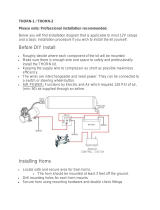
e
fr
ont
seats
o
f
the
A
u
di
Q7
is
eq
uipped
with
the
pr
oven
compact
tensio
ner
s
.
T
h
e
belt
tensioners
wor
k
a
cco
rding
t
o
the
"
b
al
l
gear"
pr
in
ci
pl
e
(no
t
USA
)
a
nd
a
r
e
trig
g
e
r
e
d
electric
a
l
ly
by
the
airb
a
g
contr
o
l
unit.
Duri
ng
a
cr
a
s
h,
the
belt
tensio
ners
a
r
e
activated
bef
o
r
e
the
fr
ont
airbags.
T
o
pr
eve
n
t
e
x
cessive
load
s
t
o
the
occupan
t
s,
the
belt
r
eels
ar
e
eq
uipped
with
belt
f
o
rce
limiters.
Above
a
specified
lo
ad
level,
th
ese
f
orc
e
l
i
m
i
ters
sla
c
k
e
n
the
bel
t
,
a
ll
o
wi
ng
the
occupa
nt
t
o
mo
ve
f
o
r
w
ar
ds
i
n
t
o
the
al
r
ea
d
y
de
pl
o
y
e
d
ai
rba
g
.
I
n
the
event
of
a
side
impa
ct
w
i
th
side
a
i
rbag
trig
gering,
the
r
e
levant
belt
tensioner
is
al
so
trig
ger
e
d.
In
the
event
o
f
a
r
e
ar
impact,
the
belt
tensioners
ar
e
also
activated,
depending
on
the
seve
rity
of
the
impac
t
.
Seat
belt
361
_
053
K
e
y
oper
ated
switc
h
t
o
deactiva
te
fr
ont
pas
s
enger
side
airbag
E224
T
h
e
key
oper
ate
d
switch
t
o
de
activate
fr
ont
pa
sse
nger
airb
ag
E224
and
the
cor
r
e
spo
n
ding
fr
ont
pa
sse
nger
side
airbag
de
activated
warning
lamp
K
145
(P
ASSENGER
AIRBA
G
OFF)
ar
e
r
e
q
u
ir
ed
in
order
t
o
deactivate
the
fr
ont
passenger
airbag.
An
illuminated
fr
ont
p
a
ssenge
r
si
de
ai
r
b
ag
deac
tiv
a
ted
warning
lamp
K145
(P
ASSEN
G
ER
AIRB
A
G
OF
F)
indic
a
tes
t
o
th
e
occupants
that
the
fr
o
n
t
passenger
a
i
r
b
ag
i
s
deac
tiva
ted.
T
h
e
contr
o
l
unit
unequivoc
a
lly
r
e
cognises
the
switch
position
by
means
of
the
ar
r
a
ngement
of
f
o
ur
r
e
sist
ors
which
ar
e
connected
in-
l
in
e,
pair
-wise.
I
f
the
airb
ag
contr
o
l
u
n
it
detects
a
f
a
ulty
key
oper
ated
switch
,
a
f
a
ult
me
mory
entry
is
made
and
the
fr
ont
pa
ss
enger
side
ai
r
b
ag
deac
tiv
a
ted
war
n
i
ng
lamp
K145
(P
ASSEN
G
ER
AIRB
A
G
OF
F)
begins
t
o
fl
a
s
h
.
A
i
rb
a
g
c
o
n
t
r
o
l
un
it
J23
4
361
_
025
19

P
a
ssenger
pr
otection
Airbag
T
h
e
fr
ont
airba
g
s
on
the
driver
and
fr
ont
passenger
sides
ar
e
eq
uipped
with
tw
o-stage
ga
s
gener
a
t
o
rs.
D
e
pending
on
th
e
natu
r
e
and
s
e
verity
of
the
accident,
the
airbag
contr
o
l
u
n
it
sets
a
time
delay
between
the
tw
o
ignitions
(fr
o
m
appro
x
.
5ms
t
o
30
ms)
.
T
h
e
loads
which
the
driver
a
nd
fr
ont
passeng
er
ar
e e
x
posed
t
o
du
r
i
ng
a
cr
a
s
h
c
a
n
be
r
e
duced
by
means
o
f
a
delayed
ignition
of
the
pr
opel
la
nt
c
h
ar
g
es.
Both
pr
opellant
c
h
arge
s
ar
e
ignited
in
all
c
a
ses.
T
h
is
pr
ev
ents
a
p
r
opella
nt
c
h
ar
g
e
fr
om
r
e
maining
a
c
tive
f
o
ll
ow
in
g
airb
ag
de
pl
o
y
m
e
nt.
Driv
er
airba
g
N95
D
rive
r
side
airbag
igniter
I
N
250
Dr
ive
r
si
de
ai
rba
g
igni
ter
II
T
h
e
g
a
s
gener
a
tor
in
th
e
driver
ai
rba
g
w
ork
s
using
tw
o
pyr
otec
hnic
pr
opellant
c
h
ar
ges.
P
r
iming
c
h
ar
g
e
Ho
u
s
in
g
Ca
p
Metal
f
i
lter
Pr
o
p
e
ll
a
n
t
ch
a
r
g
e
I
Metal
f
i
lter
P
r
opella
nt
c
h
a
r
ge
I
Bor
e
s
P
r
opella
nt
c
h
a
r
ge
II
Ig
nit
e
r
I
Ig
nit
e
r
II
361
_
014
T
h
e
driver'
s
a
i
rba
g
ga
s
gener
a
tor
is
f
l
e
x
ibl
y
mounted
in
a
ru
bber
ring
.
T
h
is
minimises
an
y
vib
r
ation
at
the
steering
wh
ee
l.
T
h
e
ga
s
g
e
ner
a
t
o
r
ac
ts
a
s
a
vi
brati
o
n
damper
.
20
/