0
11.5
11.5
8.5
8.5
23 17
0 5 10 20
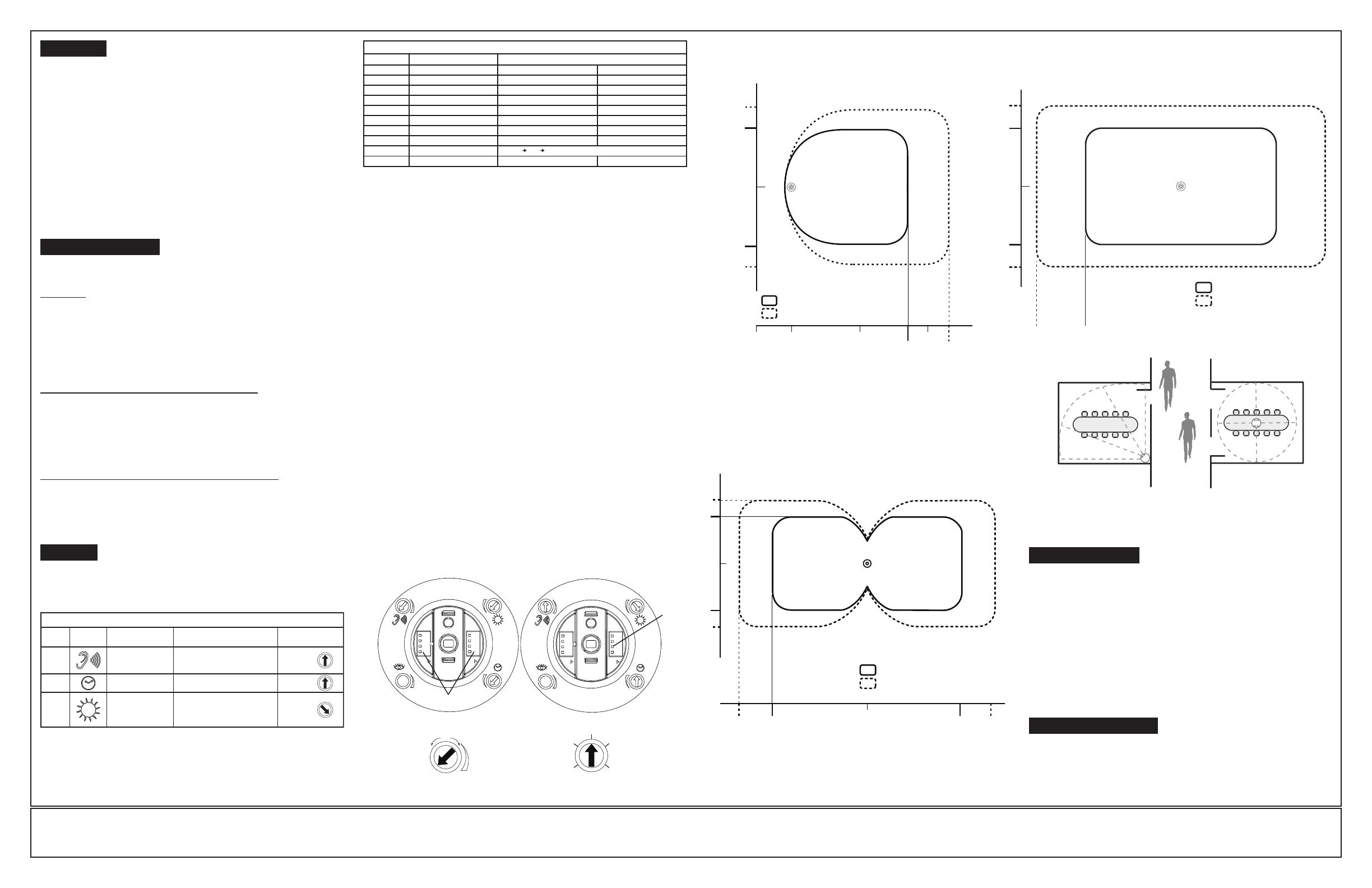
Minor Motion, Ultrasonic
Major Motion, Ultrasonic
TOP VIEW
Figure 2 (Cat. No. OSC05)
Field-of-View Ranges
0
11.5
11.5
8.5
8.5
TOP VIEW
23 23 17 17
0
Minor Motion, Ultrasonic
Major Motion, Ultrasonic
Figure 3 (Cat. No. OSC10)
Field-of-View Ranges
TROUBLESHOOTING
• Lights do not turn ON
– Circuit breaker or fuse has tripped.
– Low-voltage miswired. To Test: Connect RED to BLUE wire at power
pack to force lights ON.
– Line voltage miswired. To Test: Connect BLUE to BLUE relay wires
(of power pack)to force the lights ON.
• Lights stay ON
– Constant motion. To Test: Reduce GREEN knob by 15%; remove motion source.
If unsatisfactory, move sensor.
• Light turns ON too long
– Timer setting too high. To Test: Check switch settings. Typical setting
is 10 minutes.
• For technical assistance, contact us at 1 800 824-3005
• Visit our website at www.leviton.com
PRODUCT INFORMATION
© 2016 Leviton Mfg. Co., Inc.
0
16
16
11.5
11.5
TOP VIEW
Minor Motion, Ultrasonic
Major Motion, Ultrasonic
Figure 4 (Cat. NO. OSC20)
Field-of-View Ranges
Center of Room
Installation
(sensor will cover entire room)
Corner of Room
Installation
(sensor will cover entire room)
Mounting Location Diagram
NOTE: When mounting device, do not point sensor openings towards the opening of a
door or strong air currents.
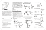
SETTINGS
Figure 1
Minimum and Default Settings
Adjust Knob Rotation
Direction
Delayed Off Time Selection
(Black Knob)
A
B
ON ON
11
A
B
ON ON
11
Minimum Setting Factory Default Setting
DIP Switches
B3
OPERATION
Motion detection by the ultrasonic sensor will turn on the lights as well as keeping them
on. When motion is not detected, the lights will turn off after the delayed-off time.
• Delayed-Off time – The sensor is designed to turn the lights off if no motion is
detected after a specified time. This length of time is called the delayed-off time
and is set using the timer (Black) knob on the sensor. The adapting patterns will
modify the delayed-off time to fit the parameters of each installation based on
environmental conditions and occupancy patterns.
• Walk-through Mode – The walk-through feature is useful when a room is
momentarily occupied. With this feature, the sensor will turn the lights off shortly
after the person leaves the room.
The walk-through feature works as follows: When a person enters the room, the
lights will turn on. If the person leaves the room before the default walk-through
timeout of 2.5 minutes, the sensor will turn the lights off. If the person stays in the
room for longer than 2.5 minutes, the sensor will proceed to the standard operation.
• LED Operation – There are two LED indicators that will flash when motion is
detected. The LED flash can be disabled using the LED disable switch setting.
Green flash indicates motion detection by ultrasonic technology.
ADAPTIVE FUNCTIONS
The Sensor continually analyzes the parameters of the motion detection signal and
adjusts its internal operation to maximize detection of motion while minimizing the
effects of noise (electrical noise, air currents, temperature changes, etc…).
Operation:
When the lights turn on, the sensor initially enters the “walk-through” mode. Once the
room is occupied for longer than 2.5 minutes, the sensor exits the “walk-through” mode
and enters the “Occupied” mode. When the sensor is first installed, the delayed-off
time for the occupied mode is based on the Time adjustment settings. While the sensor
is in use, the delayed-off time will change, based on how the sensor adapts to the room
conditions. Whenever the sensor subsequently turns on, the value of the delayed-off
time will be the adapted value (refer to Occupancy Pattern Learning For Delayed
Off Time).
The adapted settings can be reset using the DIP switch.
Occupancy Pattern Learning For Delayed Off Time:
The sensor will automatically change the delayed off time in response to the occupancy
and environmental conditions of the space it is installed in. The sensor analyzes the
motion signal properties and will minimize the delayed off time duration when there is
frequent motion detection, and lengthen the delayed off time duration when there is
weak and infrequent motion detection.
In the case of a false-off condition (lights turn off when the room is occupied), the
delayed off time duration will immediately be lengthened to prevent further false turn
offs.
Occupancy Pattern Learning for Ultrasonic Technology:
The sensor learns the occupancy patterns of a space during the course of a day, for
a seven day period. At any given time, the sensor will look at the collected data and
adjust its ultrasonic sensitivity. The sensor will adjust the sensitivity to make it less
likely to turn on during a period of non-occupancy and more likely to turn on during a
period of occupancy.
Adjustment knob settings as per “recommended manual settings,” (refer to Table 3
and Figure 1).
All switches in the off position (refer to Table 4).
TABLE 3 : ADJUSTMENT KNOB SETTINGS
Knob
Color
Green
Black
Blue
Function
Sets the ultrasonic
range
Delayed - Off Time
Ambient Light
Override
(Gray wire only)
Knob Setting
Range Setting
Full CCW = min. (OFF)
Full CW = max.
Full CCW = min. (30 sec)
Full CW = max. (30 min.)
Full CCW - Lights stay OFF
Full CW - Lights always turn ON
(NO ambient light override)
Range - 100-3000 LUX
Symbol
Factory Default
Setting
50 %
50 %
(10 min)
100 %
SWITCH
A1
A2
A3
A4
B1
B2
B3
B4
TABLE 4: SWITCH SETTINGS
SWITCH SETTINGS
Bank A
Bank B
SWITCH FUNCTIONS
N/A
N/A
Manual Mode
Walk-Through Disable
Override to ON
Override to OFF
Test Mode
LEDs Disable
ON
ON
N/A
N/A
Auto Adapting Disabled
Walk-Through Disabled
Lights Forced ON
Lights Forced OFF
LEDs Diasabled
OFF
OFF
N/A
N/A
Auto Adapting Enabled
Walk-Through Enabled
Auto Mode
Auto Mode
LEDs Enabled
OFF ON OFF = Enter/Exit Test Mode
Test Mode:
To set the delayed-off time to 6 seconds for performing a walk test. While the
sensor is in test mode, the LED’s will flash amber once a second.
1. ENSURE POWER IS ON.
2. Remove front cover.
3. Locate Dip Switch 3 in Bank B (B3) (refer to Figure 1). B3 will be in the OFF position
from the factory.
4. To enter Test Mode, move switch to ON and back to OFF. The test mode has now been
entered with a 6 second time-out. NOTE: If B3 is already in the ON position, then test
mode can be entered by just moving it to the OFF position.
NOTES:
1. The timer will remain in the 6 second test mode for 15 minutes, then automatically exit
test mode and reset to the delayed-off time setting as defined by the black timer knob.
2. To manually take the timer out of the 6 second test mode, simply toggle the switch B3
from OFF to ON and back to OFF.
Photocell (Ambient Light Override) adjustment:
In order to use the Ambient Light Override functionality of the sensor, the sensor must
be wired to the power pack (OSPXX) using the gray wire instead of the blue wire. This
feature allows the user to conserve energy by keeping the controlled lights off when not
necessary. The sensor does this by measuring the amount of ambient light in the installed
area and keeping the controlled lights off if there is enough ambient light available. To
use this feature, the Photocell adjustment (blue) knob must be adjusted from the default
position. Once this adjustment is made, the controlled lights will only turn on if the ambient
light present is less than the setting.
To set the Photocell level (used with the gray wire connection):
NOTE: This setting must be performed when the natural light is low enough to require
artificial light.
1. Remove the cover from the sensor.
2. Make note of the position of the Green knob. Rotate the Green knob full CCW and
enter the sensor’s Test mode as described above.
3. Rotate the Blue knob full CCW.
4. Wait for the lights to turn OFF.
5. Rotate the Green knob full CW.
6. Slowly rotate the Blue knob clockwise until the lights turn ON. This is the correct
setting.
7. Return the Green knob to its original position.
8. Replace cover. Setting is complete.
PK-93585-10-00-0F
MIN MAX
30 sec
5 min
30 min
20 min
10 min
LIMITED 5 YEAR WARRANTY AND EXCLUSIONS
Leviton warrants to the original consumer purchaser and not for the benefit of anyone else that this product at the time of its sale by Leviton is free of defects in materials and workmanship under normal and proper use for five years from the purchase date. Leviton’s only obligation is to correct such defects by repair or replacement, at its option. For details visit
www.leviton.com or call 1-800-824-3005. This warranty excludes and there is disclaimed liability for labor for removal of this product or reinstallation. This warranty is void if this product is installed improperly or in an improper environment, overloaded, misused, opened, abused, or altered in any manner, or is not used under normal operating conditions or not in
accordance with any labels or instructions. There are no other or implied warranties of any kind, including merchantability and fitness for a particular purpose, but if any implied warranty is required by the applicable jurisdiction, the duration of any such implied warranty, including merchantability and fitness for a particular purpose, is limited to five years.
Leviton is not liable for incidental, indirect, special, or consequential damages, including without limitation, damage to, or loss of use of, any equipment, lost sales or profits or delay or failure to perform this warranty obligation. The remedies provided herein are the exclusive remedies under this warranty, whether based on contract, tort or otherwise.