Page is loading ...

NOTE: This Drawing Is Not
To Scale!

MFJ-1798 Vertical Antenna Instructions
1
MFJ-1798 Vertical Antenna
INTRODUCTION and THEORY OF DESIGN
The MFJ-1798 is an 80 through 2 meter ground independent vertical antenna. This antenna has
several unique features including an inverted radiating element, a fully elevated counterpoise,
lumped constant end loading, and linear stub decoupling. These unique features eliminate the
traditional problems encountered in ground independent multi-band vertical designs.
Established antenna theory dictates that maximum radiation occurs in the high current portion of
the antenna. While conventional antennas generally place the highest current at the bottom or
center of the radiating element, the MFJ-1798's unique design places the highest current and the
maximum radiation point at the very top of the radiating element. This feature produces the
lowest wave angle possible for a given antenna height, and elevates the radiating section away
from the lossy earth.
It is a well-documented fact that bending or folding a radiating element at a high current point
reduces antenna system efficiency. The MFJ-1798 eliminates all bending or folding of the
important high current areas by using linear decoupling stubs on frequencies above 14 MHz.
These linear decoupling stubs provide low loss operation without compromising bandwidth.
Efficient lumped constant end loading produces the highest efficiency possible on frequencies
below 14 MHz.
Counterpoises must be an appreciable fraction of a wavelength above ground if losses are to be
minimized. The MFJ-1798 design places the counterpoise at the top of the radiating element.
This provides maximum separation between the counterpoise and the lossy earth. For example, a
ground mounted MFJ-1798 has a counterpoise elevation of one half wavelength on 10 meters.
DESCRIPTION
The MFJ-1798 is a multi-band vertical that operates on every amateur band between 80 and two
meters. The inverted radiating element is constructed from heavy duty 6061-T6 aluminum
tubing. This antenna performs as a full size inverted ground plane on all bands above 14 MHz,
and as an efficient end loaded vertical on 30, 40, and 80 meters.
The 12 feet diameter counterpoise is constructed by mounting four six feet long tubes on a
fiberglass insulated plate at the top of the antenna. The tubing has a wire that circles the
perimeter of the counterpoise to stabilize the support and increase the capacitance of the hat.
A 1/4 wave two meter vertical is mounted above the counterpoise.
Four linear decoupling stubs are tuned for 10, 12, 15, and 17 meters. These stubs are constructed
from 3/16" solid aluminum rod and supported by fiberglass insulators.

MFJ-1798 Vertical Antenna Instructions
2
A small adjustable "T" section near the bottom allows adjustment of the resonant frequency of
the full size radiating element on 20 meters.
A three section loading coil with capacitance hats for 30, 40, and 80 meters is mounted next to
the 20 meter "T" adjustment near the lower end of the antenna.
The base section contains the air core high power choke balun. This balun uses Teflon insulated
coaxial cable. The base section normally mounts on masts below 1-1/2" diameter, but additional
holes are provided to accept masts up to 2" diameter with user supplied clamps.
10 1500 2500 1250 2.0MHz
6 300 750 300 2.4MHz
2 200 200 200 7MHz
CHOOSING A LOCATION FOR THE ANTENNA
WARNING: Improper installation and assembly can be hazardous! Read these instructions
thoroughly before attempting to assemble, install or operate this product! High power
transmitting devices produce voltages that can cause severe burns or other injuries.
For the best performance on receiving and transmitting, mount this antenna in a clear location at
least a few feet above or 70 feet away from buildings, towers, feedlines, utility wires, and other
antennas. While your own ingenuity and particular circumstances will determine the final
mounting method, we will pass along few rules that can not be neglected.
Never
mount this antenna in a location that will permit unsuspecting people to come in contact
with the loading spokes or any other part of the antenna.
The power rating of this antenna varies from band to band. The PEP ratings are primarily
determined by the voltage breakdown of the components, while the CW ratings are generally
determined by component heating.
The following chart lists the power rating and the 2:1 VSWR bandwidth of this antenna:
Band
Power
Bandwidth
CW SSB RTTY
80 1000 1500 750 35KHz
40 1250 1500 1000 25KHz
30 1500 1500 1500 370KHz
20 1500 2500 1500 700KHz
17 1500 2500 1500 680KHz
15 1500 2500 1500 800KHz
12 1500 2500 1250 750KHz

MFJ-1798 Vertical Antenna Instructions
3
Never
mount this antenna where a mechanical failure might allow the antenna to contact power
lines or other utility wires.
Always
ground the feed line at the point where it enters a building to a good earth ground for
lightning protection.
MOUNTING LOCATION
WARNING: Always mount this antenna so that it is out of the reach of adults as well as
children. Contact with any part of this antenna can cause injury and / or severe RF burns.
The ideal antenna mounting location is an open area either above or more than 70 feet away from
other large conducting objects or antennas. If such a location is
not
available, the least obstructed
location should be selected.
This antenna should be mounted on a rigid support. The mounting clamps supplied with this
antenna accept masts between one and 1.5 inches outside diameter. Additional holes in the mount
of this antenna will accept mast clamps up to 2" OD. Soft or thin wall masts should not be used
to mount this antenna to any supporting structure.
The MFJ-1798 will perform quite well in ground mounted installations. The lower end of the
antenna should be at least 5 ft above ground level. If the antenna is ground mounted, it MUST be
surrounded with a protective non-metallic fencing. This will increase the safety and lessen the
likelihood of damage to the antenna.
GROUNDING
Unlike most verticals, this antenna does not require an RF ground system. However, some sort of
earth connection is a good idea to avoid lightning damage to the station equipment and to
improve operator safety.
The feedline's shield should be grounded at the entrance point of the building before it reaches
the operating position. Failure to do so can result in lightning damage to the equipment. This will
also help prevent voltage from being applied to the antenna support if the station equipment ever
develops a problem.
Additional lightning protection can be achieved by burying the feedline directly in the soil for a
minimum of 10 feet before the cable enters the building. It is also an excellent idea to ground the
mast or supporting structure.
Grounds should consist of multiple rods driven into the soil. Several long straight buried wires
will assist in dissipating lightning strikes. Leads from the ground system to the antenna mast or
coaxial cable should be as short and direct as possible. Sharp bends in the ground leads should be
avoided. It is an excellent idea to connect all the grounds together outside the building with

MFJ-1798 Vertical Antenna Instructions
4
smooth, wide, heavy conductors. This includes connecting the power line grounding rod to the
feedlines ground.
Never use woven flexible braiding for ground connections unless absolutely necessary. Braiding
has very high resistance to both RF and lightning. Copper flashing, wide copper foil, or large
gauge solid copper wires are the proper materials for use in RF and lightning grounding
applications.
The use of an in-line coaxial lightning arrestor will only offer a minimal improvement in
lightning protection. The best method of protecting the station equipment is to disconnect the
feedline outside the building or, at the minimum, use a safety switch to disconnect and ground
the feedline.
MAINTENANCE
Your antenna is constructed of heavy duty non corrosive materials and should withstand normal
climates for many years. The use of some type of coaxial connector moisture protection is
recommended at the bottom coax connection and also around the matching network feed point,
especially in coastal areas where salty mist is commonplace.
GE makes a pure silicone grease called "SILICONE DIELECTRIC COMPOUND" that can be
applied SPARINGLY to the threaded area of the female connector. This compound, or even a
clear silicone heat sink compound, will prevent moisture from entering the connector through the
threads and protect the connectors from corrosion. THIS IS THE SAME TYPE OF SEALER
THAT COMMERCIAL ANTENNA INSTALLERS AND CATV COMPANIES USE WITH
GREAT SUCCESS.
A less desirable but adequate sealer is the automobile seam sealer commonly sold as "coax seal".
This is a pliable black sealing compound.
When installing any coax sealer, NEVER completely cover the barrel of the coax connector. The
sealer should ONLY be placed near the junction of the threaded part of the chassis connector and
the knurled area of the male connector. This will leave the bottom of the male connector's outer
sleeve open and permit the connector to "breathe" so it does NOT collect moisture!
IMPORTANT FOR COASTAL AREA OPERATORS: It is advisable to use some type of
silicon spray (circuit board type from Radio Shack) on the capacitor rings to prevent corrosion
between the aluminum and the stainless steel screws. Corrosion on the capacitor rings tend to
make it difficult to remove the spokes to retune the antenna.
TOOLS AND TIME REQUIRED FOR ASSEMBLY
The estimated assembly time for this antenna is four to six hours. An additional one to two hours
is required to adjust the antenna on all the bands. The most convenient place to adjust this
antenna is on a ground mounted temporary mast or support.

MFJ-1798 Vertical Antenna Instructions
5
The required tools are:
1/4" standard screwdriver
3/8" open end wrench
5/16" nut driver
7/16" nut driver
7/16" open end wrench
Large wire cutters
#1 Philips screwdriver
#2 Philips screwdriver
Eye protection
Temporary mast (5-8').
Step ladder or saw horses.
One soldering iron
MFJ-1798 PARTS LIST
NOTE All screws and nuts are stainless steel.
As you unpack this antenna you should find the following parts.
In the event any parts are missing, please contact us
immediately.
Group A
Packed loose in box or inserted inside each other:
[ ] One 30" long, 1" dia. fiberglass loading coil assembly
[ ] One bundle of 14 long capacitance hat spokes
[ ] One bundle of 4 short capacitance hat spokes
[ ] One 6' long 6060-T6 aluminum tubing 1-3/8" OD.
[ ] One 6' long 6061-T6 aluminum tubing 1-1/4" OD.
[ ] One 50'' long 6061-T6 aluminum tubing 1-1/8" OD.
[ ] Four 6' long 6061-T6 aluminum tubing 1/4" OD.
The following bundle of 3/16" diameter aluminum rods:
Threaded rods Non-threaded rods
[ ] Four 55" [ ] Four 72"
[ ] One 19" [ ] One 66.5"
[ ] One 48"
[ ] One 41"
[ ] One 15"
[ ] One fiberglass base insulator mounted on a heavy aluminum bracket

MFJ-1798 Vertical Antenna Instructions
6
[ ] One balun and feedline assembly with small coil and capacitor
network
Group B (Hardware Bag #1)
[ ] One bag of hardware containing the following parts groups:
(1) Five #4 self tapping screws (4) Twenty-nine 6-32 nuts
Five 4-40 x 3/8" screws Two 10-32 split ring washers
Five 1/4-20 x 1-3/4" bolts
Four #4 flatwashers
Five 1/4" split ring washers
(2) Thirty 6-32 x 1/4" screws (5) Six 3/16" ID aluminum couplers
Twelve 10-32 nuts Six black cable ties
Two white nylon insulators
(3) Twenty-seven 6-32 x 5/8'' screws One red plastic cap
Two 10-32 x 1-3/4" screws
Five 1/4-20 nuts
Group C (Hardware Bag #2)
[ ] One bag of large hardware containing the following parts groups:
(1)Three small aluminum "L" brackets (3) Four counterpoise clamps with no flange
Three triangular aluminum brackets Four counterpoise clamps drilled flange
One rectangular aluminum bracket One 20 meter adjustment "U" clamp
(2)Five flat rectangular fiberglass stub insulators
One set of fiberglass and aluminum
counterpoise support assembly plates
One hollow center, square aluminum plate
Group D (Hardware Bag #4)
[ ] One bag containing the following:
Seven hose clamps (4 clamps are pre-installed on the angle
bracket in this bag.
3 clamps are packed loose in the bag to be sed in
step 9, 10,
and 11 on page 11.)
Two "U" bolts with saddle brackets, nuts, and split wahers to fit
masts under 1-1/2" OD
35" (approximately) of small tinned wire

MFJ-1798 Vertical Antenna Instructions
7
One large angle bracket (with four host clamps) with slots for
mounting loading coil
ADDITIONAL USER SUPPLIED MATERIALS
Please be sure you have the following additional items available:
[ ] A 6'-8' rigid mast or other mounting pipe between 1" and 1.5" outside diameter (suitable
materials include a heavy duty TV mast section or galvanized steel pipe).
[ ] Quality low-loss 50-Ohm coax with PL-259 connectors to reach from antenna to transmitter.
[ ] A SWR meter or Analyzer (MFJ-207, MFJ-249 or equivalent).
[ ] Enough 1/8 to 3/16" nylon rope to reach the ground from the antenna's final location.
SAFETY PRECAUTIONS!!
Please remember the following important points:
1.) THIS ANTENNA IS AN ELECTRICAL CONDUCTOR.
2.) ANY CONTACT BETWEEN THE ANTENNA, FEEDLINE, OR
SUPPORTING STRUCTURE AND POWER LINES WILL RESULT IN
DEATH OR SERIOUS INJURY.
For safety please:
1.) DO NOT INSTALL THIS ANTENNA WHERE THERE IS ANY
POSSIBILITY OF CONTACT WITH UTILITY LINES.
2.) DO NOT LOCATE THE ANTENNA SUPPORT WHERE IT CAN
CONTACT POWER LINES IN THE EVENT OF MECHANICAL
FAILURE OR ACCIDENT.
3.) FOLLOW THE GUIDELINES FOR ANTENNA INSTALLATIONS AS
RECOMMENDED BY THE US CONSUMER PRODUCT SAFETY
COMMISSION.
ASSEMBLY PROCEDURE
During assembly, refer to the drawings throughout this manual and
the overview drawing on Page 1. Follow these instructions in the
exact sequence listed to avoid errors and achieve maximum
performance from this antenna.

MFJ-1798 Vertical Antenna Instructions
8
After the antenna is assembled, you must double check the
hardware for proper tightening and assembly. The resonant
frequency and SWR can be tested with the antenna only a few feet
above ground on a temporary support before raising it to the
final tower or rooftop position.
NOTE:
Wear safety glasses whenever working near or on this
antenna.
WARNING! You can be killed if the antenna, feed line, or the
equipment used to install the antenna accidentally contacts any
utility lines. Never install an antenna near power lines!
1.
Be especially careful while moving or installing this antenna. This antenna is bulky enough to
cause a loss of balance if handled by an inexperienced person, or if the counterpoise or a
capacitance spoke accidentally becomes snagged on a gutter, a tree limb, or any other object.
2.
Mount the antenna high enough to place it completely out of reach, or protect it with a fence.
The ends of the capacitance spokes and other areas of the antenna can cause eye injury, serious
RF burns, or both.
3.
Be sure the mast is sturdy enough to support 20 pounds of weight and a wind load of
approximately 3 square feet.
Step By Step Assembly Procedure
1- Prepare a temporary 5'-6' ground-level mounting mast. This temporary mast will simplify the
initial testing and adjustment of this antenna. It is also a good idea to have one or two stable
supports (table, saw horses, etc.) and a 6' step ladder available at the assembly location.
2- Be sure the parts are separated in the groups listed earlier. Be sure all of the parts are available
BEFORE beginning the actual antenna assembly.
3- Gather the following tools for the basic assembly. At minimum, these consist of:
• - #1 Philips screwdriver for capacitance spokes screws
• - #2 Philips screwdriver for other 6-32 and 10-32 screws
• - 1/4" standard screwdriver or 5/16" nut driver for hose clamp
• - 3/8 open end wrench for stub adjustments
• - Two 7/16 open end wrenches or one wrench and a 7/16" nut driver for
U bolts and coupling bolts
• - Wire cutter for trimming capacitance spokes and counterpoise wire
• - Safety glasses
• - One soldering iron

MFJ-1798 Vertical Antenna Instructions
9
NOTE
- A small adjustable crescent wrench can substitute for the 3/8" and 7/16" open
end wrenches.
IMPORTANT: Do not use a high torque electric screwdriver to mount the
capacitance spokes or any of the #4 through #10 hardware.
The hardware may be damaged if excessive or uncontrolled
torque is applied during assembly.
Locate the following parts
. The abbreviation "Gp" precedes the Group the part is located in:
One fiberglass base insulator and mounting bracket assembly (Gp A)
One balun and feedline assembly (Gp A)
Two 1/4-20 x 1-3/4" bolts (Gp B1)
Four 6-32 x 5/8" screws (Gp B3)
Two 1/4-20 nuts (Gp B3)
Two 1/4" split ring washers (Gp B4)
Four 6-32 nuts (Gp B4)
Two white nylon insulators (Gp B5)
U-bolt
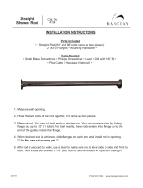
Referring to figure 1:
4- Install the U-bolts on the open face of the base insulator mounting bracket.
Mount the saddle clamps with the flat side against the plate, and the toothed side facing the
rounded U-bolt area. These clamps will secure the antenna to the mast.
5- Put the lock washers over the 1/4-20 bolts and slide one of the bolts through the upper balun
mounting hole on the side bracket of the base mounting plate. The upper mounting hole is
located at the end of the bracket where the fiberglass insulator sticks out.
6- Use a white nylon insulator to space the balun away from the bracket, and be sure the balun
hole closest to the end of the balun with the very long lead is bolted to the top bracket hole.
Install the nut inside the balun form. Finger tighten only.
7- Attach the bottom balun hole to the bottom hole in the mounting assembly as explained in step
5. Snug both bolts until the split ring washer just collapses with a 7/16" wrench.
8- Bolt the coax connector housing to the base mounting assembly with four 6-32 x 5/8" screws
and 6-32 nuts.
Figure
1

MFJ-1798 Vertical Antenna Instructions
10
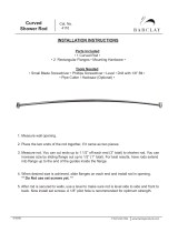
In the following steps you will refer to figure 2.
Locate the following parts:
One 72" long 1-3/8" tubing (A)
One 72" long 1-1/4" tubing (A)
One 50" long 1-1/8" tubing (A)
Three 1/4-20 bolts (B1)
Three 1/4-20 nuts (B3)
Three 1/4" split washers (B4)
Three hose clamps (D)
You will use a 1/4" bolt with a lock washer under the 1/4" nut to secure
the tubing sections together. These bolts are only used to "pin" the tubing
in place.
DO NOT OVER TIGHTEN THE NUTS, doing so will flatten the tubing and
actually weaken the structure.
A hose clamp provides additional support. Be sure to properly
snug the hardware after each step.
The antenna can be laid on the ground during this stage
of assembly.
Figure
2

MFJ-1798 Vertical Antenna Instructions
11
9- Find the end of the 1-3/8" tubing that has a 1/4" hole
located around four inches from the end. Insert the solid
fiberglass base insulator on the base mount into this end
of the tubing. Use a 1/4" bolt to secure the tubing. Place a
hose clamp over the outer end of the slit area of the
tubing.
10- Find the end of the 1-1/4' diameter tubing that has a
1/4" hole one inch from the end. Slide this end into the 1-
3/8" tubing used in step 9. Secure the tubing with a bolt
and a hose clamp over the outer end of the slit.
11- Find the end of the 1-1/8" diameter tubing with a hole
at 1" from end. Slide this end into the tubing used in step
10. Secure it with a bolt and a hose clamp over the end of
the slit.
In the following steps you will refer to figure 3. Locate
the following parts:
Two 10-32 x 3/8" nuts (B2)
Two 10-32 x 1-3/4" screws (B3)
Eight 6-32 x 5/8" screws (B3)
Two #10 split washers (B4)
Eight 6-32 x 3/8" nuts (B4)
One red plastic cap (B5)
One rectangular support bracket (C1)
Three triangular support brackets (C1)
One set of fiberglass and aluminum counterpoise support assembly plates (C2)
12- Position the counterpoise mounting plate so that the edge lip (aluminum side) is facing up.
Assemble the counterpoise mounting plate by using eight 6-32 x 5/8" screws to secure the three
triangular and one rectangular support brackets as shown in the drawing. All the edge flanges
should point clockwise. Be certain that the rectangular plate's edge flanges are facing (and next
to) the 2 meter element's mounting hole.
Note:
Do not tighten these screws at this time.
13- Position the plate so that the brackets are facing the base of the antenna. Slide the plate over
the 1-1/8" tubing (top of antenna). Align the holes and secure the plate with two 10-32 x 1-3/4"
screws with split washers under the nuts. Tighten the eight 6-32 support bracket screws installed
in step 12 and place the plastic cap plug over the top of the tubing.

MFJ-1798 Vertical Antenna Instructions
12
Refer to figure 4 for the next assembly steps.
Locate the following parts:
Six 6-32 x 5/8" screws (B3)
Six 6-32 nuts (B4)
Three small "L" brackets (C1)
Five flat rectangular fiberglass stub insulators (C2)
14- With four fiberglass stub insulators and two aluminum "L" support brackets, make two
insulating "X" brackets. Each "X" bracket is made by sandwiching one "L" support bracket
between a pair of rectangular fiberglass insulators with two 6-32 x 5/8" screws and nuts
(remember to look at figure 4).
15- Construct a fiberglass "I" bracket by assembling the remaining "L" support bracket and
fiberglass insulator with two 6-32 x 5/8" screws and nuts.
Figure
3

MFJ-1798 Vertical Antenna Instructions
13
NOTE: Make sure all brackets are
assembled the in the same manner
(fit on top of each other the same
way). This is to help you to mount
them on the same side of the
antenna and keep them lined up.
NOTE:
At this point it will be useful to "prop up" the element
with a small support.
16- Place a hose clamp over the 1-1/8" tubing near the junction of the 1-1/4" tubing. Install the
"X" bracket under this clamp. Align the holes in the "X" bracket with the holes in the
counterpoise support plate. Secure the bracket with the hose clamp.
17- Using a similar procedure, install the second "X" bracket approximately four feet closer to
the base mount than the position of the first bracket.
18- Install the remaining fiberglass "I" bracket and hose clamp approximately eight feet lower
than the first "X" bracket. Position it parallel with any two adjacent holes in the square support
section of the feed plate and the "X" brackets. After aligning it can be secured with the clamp.
Locate the following parts:
Six 3/16" ID couplers (B5)
Four 55" threaded rods (A)
Two 72" non-threaded rods (A)
One 66.5" non-threaded rod (A)
One 48" non-threaded rod (A)
One 41" non-threaded rod (A)
One 15" non-threaded rod (A)
Twelve 6-32 x 1/4" screws (B12)
Eight 10-32 nuts
19- Install all twelve 6-32 screws finger tight in the couplers.
20- Slide four couplers half-way over the non-threaded end of the four 55"
threaded
rods. Slide
two couplers half-way over the ends of the two 72" rods. Secure the couplers.
Figure
4

MFJ-1798 Vertical Antenna Instructions
14
21- Pass the threaded end of the rods through the holes of the first X-bracket. Thread one 10-32
nut down 2" on the threaded portion of each rod.
22- Pass the threaded rod ends through the four stub mounting holes at the outside middle of the
counterpoise support plate. Thread four 10-32 nuts on the rods and tighten snugly.
Note: Install the 17 and 15 meter stubs, and the 10 and 12 meter stubs,
on opposite sides of the mast.
23- Connect the remaining 3/16" rods to the previously installed stub sections using the
construction chart above. You will use the remaining couplers to fasten the various lengths
together (refer to Figure 5 for location of elements).
Locate the following parts:
Two #10 nuts
At this point you should have
four 53" stubs hanging down
from the counterpoise support
plate. These stubs should be
parallel with the main antenna
mast. In the following steps, you
will add the proper additional
physical length to make each
stub look like a 1/4 wave
radiator on 10, 12, 15 and 17
meters.
The 17 meter stub (the longest
stub) should be located on the
same side of the main mast as
the balun coil. The 15 meter
stub should be on the exact
opposite side of the mast.
Figure
5
10m
12m
15m
17m
66.5"
72"
72" 15"
41"
48"53"
53"
53"
53"
Threaded Ends

MFJ-1798 Vertical Antenna Instructions
15
One 19" rod threaded one end
Six black cable ties
24- Thread a #10 nut 1" in from the outer end of the 19" element. Mount the 19" element in the
"2 meter element" hole of the counterpoise support plate (see page 11, figure 3). Insert the
threaded end of this element into the top of the hole so it sticks out ABOVE the top of the antenna
(away from the base mount and the other stubs). Install a second nut below the plate to secure the
element. Install this nut loosely for the moment!
25- Dress the long coaxial cable along the main element from the balun to the top of the antenna.
Ground the solder lugs near the balun end of the coaxial cable to the 1-3/8" diameter tubing by
placing one lug under the hose clamp and the other lug under the 1/4" base mounting bolt.
Tighten the 1/4" bolt snugly now. Ground the coax ground lugs to antenna along the feedline.
26- Secure the coaxial cable to the tubing by evenly spacing the black cable ties
along the cable.
Important:
Keep the Coax cable feeding at least 1-1 1/2" away from the antenna mounting
bracket. Failure to do so will cause arking problems on high power between the mounting
bracket and feedline, which could damage the feedline and possisbly your equipment.
Locate the following parts:
Four 1/4" x 6' aluminum tubing (A)
Four 4-40 x 3/8" screws (B1)
Four 4-40 flat washers (B1)
Eight 6-32 x 5/8" screws (B3)
Ten 6-32 nuts (B4)
Four counterpoise clamps without flange (C3)
Four counterpoise clamps with flange (C3)
One square aluminum plate with hollow center (C2)
Counterpoise wire (D)
Four counterpoise clamp wires
additionally: a soldering iron and a step ladder or other 5-6' tall support
27- Thread the four 4-40 x 3/8" screws fully into the cap nut at the end of each 1/4" tubing.
Do
not tighten them yet.
28- Place the top of the antenna on a high stable support (such as a 6' step ladder) before starting
the counterpoise assembly.
29- Prepare seven counterpoise clamps (four without the flange and three with the drilled
flanges). Thread a 6-32 nut down the head of each 3-32 x 5/8" screw. Install three 6-32 x 5/8"

MFJ-1798 Vertical Antenna Instructions
16
screws into the
PEM
TM
nuts, from the outside end, of three drilled flange counterpoise clamps
(Figure 6).
30- Install the four other screws by passing them through the
solder lungs of the counterpoise clamp wires, then threading them
into the counterpoise clamps with no flange (Figure 6).
31- Thread a 6-32 nut down to the head of a 6-32 x 5/8" screw. Pass the screw through the solder
lug on the red lead that connects to the capacitor junction of the Matching Network. Thread the
screw into the remaining drilled flange counterpoise clamp (see Figure 5).
32- Install the counterpoise clamp with the red wire attached in the
innermost slot located next to the square support bracket and the 2 meter
element. Make sure the drilled flange is pointing outward (see Figures 6 and 7).
33- Install a no flange counterpoise clamp in the outside slot in the fiberglass counterpoise
support plate in line with the clamp installed in the previous step.
34- Slide the empty end of the remaining 1/4" OD x 6' long aluminum element through the clamp
holes. Tighten the clamp screws to secure the tubing. Use a 5/16" nut driver or small wrench to
snug the nut down on the solder lug (see Figs. 6 and 7).
Note: Make sure the element end is between 1/4 and 1/2" away from the main element 1-
1/8" tubing. Be sure that the solder lugs are only touching the metal they are bolted
to, and NOT accidentally touching (or very close to) any other metal parts!
35- Connect the white wire (from trace that connects to the coax shield) by placing the lug over
either 6-32 mounting screw on the rectangular counterpoise plate support bracket. Installing a
new 6-32 nut over the solder lug to secure it (see figure 7).
Figure
6

MFJ-1798 Vertical Antenna Instructions
17
36- Connect the black wire (from the coax center conductor) to the 2 meter
element by removing the #10 mounting nut and replacing it over the black
wire's solder lug (see Figure 5).
37- Attach the matching network to the square support bracket (coaxial cable towards center of
antenna) by inserting the 6-32 x 3" screws in the matching holes. Install two new 6-32 nuts to
secure the coil's mounting screws to the rectangular bracket (see Figure 7).
Figure
7

MFJ-1798 Vertical Antenna Instructions
18
38- Mount the three remaining 1/4" x 6' long tubes in
position using the remaining clamps. Be sure that the
clamps with the drilled flange are in the innermost slots and
have their flanged ends pointed outwards. Be sure the tubes
are between 1/4 and 1/2 inch from the 1-1/8" main element.
Tighten the no-flange counterpoise clamps ONLY.
39- The counterpoise wires connected together with the
square hollow center plate. Use four #4 self- tapping screws
to attach the hollow center square plate to the flange holes
of the inner counterpoise clamps (see Figure 8). DO NOT
OVER TIGHTEN THE SCREWS but be sure that they are
fully seated on the plate's surface.
40- Use a 5/16" nut driver to tighten all 6/32 nuts on the
flanged counterpoise clamps and the non-flanged clamps.
Make sure that counterpoise rods are mechanically
secure.
WARNING:
The counterpoise tubing must stay at least
1/4" from the 1-1/8" tubing.
41- Connect the outer ends of the counterpoise together using the wire
provided. Connection is made by wrapping the wire once around the 4-40
screw between the flat washer and the cap nut on the end of the
counterpoise rod before tightening the screw.
41- Mount the angle mounting bracket of the trap assembly at the bottom of the antenna and
make sure it is pointing to the opposite side of the 17m stub and away enough from the balun
(refer to Figure 10).
42- Raise the antenna to a temporary mast (5-8'), and secure it using the two U-bolts on the
mounting base.
Warning:
Be especially careful when moving or mounting this antenna. The weight
and length of this antenna can cause a loss of balance if handled by an
inexperienced person, or if the counterpoise or a capacitance spoke
accidentally becomes snagged on a gutter, a tree limb, or any other object.
Locate the following parts:
Twelve long capacitance hat spokes (A)
Figure
8

MFJ-1798 Vertical Antenna Instructions
19
Four short capacitance hat spokes (A)
Sixteen 6-32 x 1/4" screws (B2)
One 30" fiberglass loading coil assembly (A)
Four hose clamps (D)
Warning:
Only tighten the screw that fastens the loading coil
terminal lugs to the capacitance hat if the ring is
loose. Never excessively tighten the screw or you can
BREAK the fiberglass form. If the terminal lugs are
loose, tighten the NUT against the lug
.
43- Install the short 6-32 x 1/4" screws in the rings of loading coil assembly. Do not thread the
screws completely in. Install six long capacitance spokes in the six holes in the 80-meter
capacitance hat ring. Tighten the screws until the spokes are snug. At this point you should be
able to stand the coil form on its end. Use either a #5 or #2 screwdriver here (see Figure 9).
44- Install the six remaining long spokes in the six holes in the 40 meter capacitance hat ring,
then install four short spokes in the 30 meter capacitance hat ring.
45- Mount the coil assembly in the angle mounting bracket. Place the solder lug under the first
hose clamp. Tighten both hose clamps.
Do not over tighten the hose clamps, you may break
the fiberglass form, or the clamps.
See Figure 10.
/