Page is loading ...

DM-TX-201-C
DigitalMedia 8G+
®
Transmitter
Supplemental Guide
Crestron Electronics, Inc.

The product warranty can be found at www.crestron.com/warranty.
The specific patents that cover Crestron products are listed at www.crestron.com/legal/patents.
Certain Crestron products contain open source software. For specific information, please visit www.crestron.com/opensource.
Crestron, the Crestron logo, Cresnet, Crestron Connect It, Crestron Toolbox, DigitalMedia, DigitalMedia 8G+, DM, and DM 8G+ are either
trademarks or registered trademarks of Crestron Electronics, Inc. in the United States and/or other countries. HDBaseT and the HDBaseT
Alliance logo are either trademarks or registered trademarks of the HDBaseT Alliance in the United States and/or other countries. HDMI and
the HDMI logo are either trademarks or registered trademarks of HDMI Licensing LLC in the United States and/or other countries. Other
trademarks, registered trademarks, and trade names may be used in this document to refer to either the entities claiming the marks and
names or their products. Crestron disclaims any proprietary interest in the marks and names of others. Crestron is not responsible for errors
in typography or photography.
This document was written by the Technical Publications department at Crestron.
©2017 Crestron Electronics, Inc.

Supplemental Guide – DOC. 6598D Contents • i
Contents
Introduction 1
Physical Description 2
Top View ....................................................................................................................... 2
Front View ..................................................................................................................... 3
Rear View ...................................................................................................................... 4
Communications Using Crestron Toolbox Software 5
Communications via a DM Switcher .............................................................................. 5
Using USB Communications ................................................................................... 5
Using TCP/IP Communications ............................................................................... 6
Communications via the LAN Port of the DM-TX-201-C ................................................ 7
IP Table Configuration ................................................................................................... 8
Configuration Using DMTool .......................................................................................... 8
Firmware Upgrade 9
Troubleshooting 10
Appendix: Pin Assignments 11


Supplemental Guide – DOC. 6958D DM-TX-201-C: DigitalMedia 8G+ Transmitter • 1
DM-TX-201-C:
DigitalMedia 8G+
®
Transmitter
Introduction
The Crestron
®
DM-TX-201-C provides an interface for computers and high-definition AV
sources as part of a complete Crestron DigitalMedia™ system. The DM-TX-201-C functions
as a DM 8G+
®
transmitter and switcher, providing HDMI
®
, RGB, and analog audio inputs as
well as Ethernet and USB HID ports. In addition to compatibility with other
DM 8G+ devices, the DM-TX-201-C is also compatible with HDBaseT
®
compliant devices.
The DM-TX-201-C provides simple switching between the HDMI and RGB inputs.
The inputs can be configured to switch automatically or can be controlled through a
Crestron control system. Analog audio breakaway capability enables the analog audio input
of the DM-TX-201-C to be used with either video input. The DM-TX-201-C also functions as
a keyboard/mouse extender, allowing the connected USB HID compliant host to be
controlled by a mouse and/or keyboard that is located at a remote location.
Additional features of the DM-TX-201-C include the following:
• Local HDMI output, which enables pass-through of the selected video and audio
signals to feed a local display, monitor, or sound system
• 10BASE-T/100BASE-TX LAN port, which can be used to provide a convenient LAN
connection for a local network device
• CEC embedded device control, which provides a gateway for controlling the
connected source device through the HDMI connection
• Compatibility with TT-100 Series devices (Crestron Connect It™ cable caddies)
• Detection and reporting of detailed video and audio information via DMTool
This manual provides information about the following:
• Physical description of the connectors, controls, and indicators on the
DM-TX-201-C
• Communications using Crestron Toolbox™ software
• Firmware upgrade
• Troubleshooting
• Pin assignments
For installation information, refer to the DM-TX-201-C DO Guide (Doc. 7719). The document
is available at www.crestron.com/manuals
.

2 • DM-TX-201-C: DigitalMedia 8G+ Transmitter Supplemental Guide – DOC. 6958D
Physical Description
The following sections provide information about the connectors, controls, and indicators
that are available on the top, front, and rear of the DM-TX-201-C.
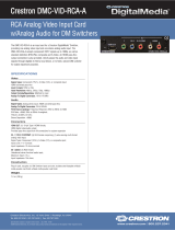
Top View
The following illustration shows the top of the DM-TX-201-C.
Top View
RESET: Recessed push button for hardware reset

Supplemental Guide – DOC. 6958D DM-TX-201-C: DigitalMedia 8G+ Transmitter • 3
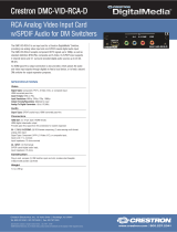
Front View
The following illustration shows the front of the DM-TX-201-C.
Front View
LAN: 8-pin RJ-45 female, shielded, with two LED indicators;
10BASE-T/100BASE-TX Ethernet port;
Green LED indicates Ethernet link status;
Amber LED indicates Ethernet activity
DM OUT: 8-pin RJ-45 female, shielded, with two LED indicators;
DM 8G+ output, HDBaseT compliant;
PoDM and HDBaseT PoE powered device (PD) port
1
;
Connects to the DM 8G+ input of a DM
®
switcher, receiver/room controller, or other
DM device, or to an HDBaseT device via CAT5e or Crestron DM-CBL-8G cable;
Green LED indicates DM link status;
Solid amber LED indicates HDCP video;
Blinking amber LED indicates non-HDCP video
HDMI OUT: 19-pin Type A HDMI female connector;
HDMI digital video/audio output (DVI compatible);
2
PWR 24 VDC 0.75A: 2.1 x 5.5 mm dc power connector;
24 volt dc power input;
Power pack included
Power LED: Green LED, indicates operating power supplied from local power pack,
PoDM, or HDBaseT PoE
Ground: 6-32 screw, chassis ground lug
1
In order for the DM-TX-201-C to receive PoDM, the DM-TX-201-C requires connection to a DM switcher or other
DM equipment that has a PoDM power sourcing equipment (PSE) port. In order for the DM-TX-201-C to receive
HDBaseT PoE, the DM-TX-201-C requires connection to equipment that has an HDBaseT PoE PSE port.
Any wiring that is connected to a PoDM or HDBaseT PoE port is for intrabuilding use only and should not be
connected to a line that runs outside of the building in which the PSE is located.
2
The HDMI OUT connection requires an appropriate adapter or interface cable to accommodate a DVI or
Dual-Mode DisplayPort signal. CBL-HD-DVI interface cables are available separately.

4 • DM-TX-201-C: DigitalMedia 8G+ Transmitter Supplemental Guide – DOC. 6958D
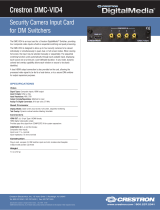
Rear View
The following illustration shows the rear of the DM-TX-201-C.
Rear View
SETUP: Red LED and miniature recessed push button for Ethernet setup
AUDIO IN: 3.5 mm TRS mini phone jack;
Unbalanced stereo line level audio input;
Input level: 2 Vrms maximum;
Input impedance: 10 k ohms
RGB IN: HD15 female;
Analog VGA/RGB/video input;
Signal types: VGA, RGB, component, S-Video, or composite
1
;
Formats: RGBHV, RGBS, RG
S
B, YPbPr
,
Y/C, NTSC, PAL;
Input levels: 0.5 to 1.5 Vp-p with built-in dc restoration;
Input impedance: 75 ohms;
Sync input type: Autodetect RGBHV, RGBS, RG
S
B, YPbPr;
Sync input level: 3 to 5 Vp-p;
Sync input impedance: 1 k ohm
RGB IN LED: Green LED, indicates RGB input is selected
HDMI IN: 19-pin Type A HDMI female;
HDMI digital video/audio input (DVI and Dual-Mode DisplayPort compatible)
2
HDMI IN LED: Green LED, indicates HDMI input is selected
USB HID: USB Type B female;
USB 2.0 device port for connection to the USB host interface of a computer or other
USB HID compliant host device, or for connection of a Crestron TT-100 Series device
(Crestron Connect It cable caddy)
3
1
The RGB input can accept component, composite, and S-Video signals through an appropriate adapter
(not included) or via direct interface to the Crestron MPS Series products. However, input sync detection is not
provided for composite or S-Video signal types through this connection.
2
The HDMI IN connection requires an appropriate adapter or interface cable to accommodate a DVI or
Dual-Mode DisplayPort signal. CBL-HD-DVI interface cables are available separately.
3
The USB HID port does not supply USB power. When connected to a TT-100 Series device (sold separately), the
TT-100 Series device must be powered separately through a connection to a Cresnet
®
network or power supply.

Supplemental Guide – DOC. 6958D DM-TX-201-C: DigitalMedia 8G+ Transmitter • 5
Communications Using Crestron Toolbox Software
Crestron Toolbox software enables communications with the DM-TX-201-C.
Communications with the DM-TX-201-C can occur in the following ways:
• Via a DM switcher (DM-MD8X8, DM-MD16X16, or DM-MD32X32)
• Via the LAN port of the DM-TX-201-C. In this scenario, the DM-TX-201-C is used in
a stand-alone configuration in which it does not connect to a DM switcher.
Communications via a DM Switcher
Communications with the DM-TX-201-C can be accomplished using USB or TCP/IP
communications between a PC running Crestron Toolbox software and a DM switcher.
NOTE: TCP/IP provides a faster method of communications than USB and is required for
operation with a Crestron control system.
Using USB Communications
Use Crestron Toolbox software to establish USB communications between a PC and a DM
switcher.
NOTE: The Type A to Type B USB cable included with a DM switcher connects the USB
port on a PC to the COMPUTER port on the DM switcher.
USB Communications via a DM Switcher
To establish USB communications between a PC and a DM switcher, do the following:
1. Using the Address Book, create an entry using the USB communications protocol.
When multiple USB devices are connected, identify the DM switcher by entering
information into the following text boxes:
• Model: Enter the model name (DM-MD8X8, DM-MD16X16, or DM-MD32X32)
of the DM switcher.
• Serial: Enter the serial number of the DM switcher.
• Hostname: Enter the hostname of the DM switcher.
NOTE: The hostname can be found in the System Info window in the section
marked "Ethernet;" however, communications must be established in order to
see the hostname in the System Info window.
PC running
Crestron Toolbox™
software
USB
DM switcher
DM 8G+
®
transport
DM-TX-201-C

6 • DM-TX-201-C: DigitalMedia 8G+ Transmitter Supplemental Guide – DOC. 6958D
2. In the Crestron Toolbox toolbar, click . The System Info window opens.
3. In the drop-down list at the bottom of the System Info window, select the entry of
the DM switcher. Device information is displayed.
Using TCP/IP Communications
Use Crestron Toolbox software to establish TCP/IP communications between a PC and a
DM switcher.
TCP/IP Communications via a DM Switcher
To establish TCP/IP communications via a PC and a DM switcher, do the following:
1. For the IP address of the DM switcher, use DHCP (default setting) or set a static IP
address. If DHCP is to be used, proceed to step 2. If a static IP address is to be
set, skip step 2 and proceed to step 3.
2. (Applicable to DHCP only) Use the Device Discovery Tool to find the IP address of
the DM switcher.
3. (Applicable to static IP address only) To set a static IP address, do the following:
a. Establish USB communications between the PC and the DM switcher as
discussed in "Using USB Communications" on page 5
b. In the Functions menu, select Ethernet Addressing.
c. Enter the IP address, IP mask, and default router of the DM switcher.
4. In the Address Book, create an entry for the DM switcher by using the IP address of
the DM switcher.
5. In the Crestron Toolbox toolbar, click . The System Info window opens.
6. In the drop-down list at the bottom of the System Info window, select the entry of
the DM switcher. Device information is displayed.
PC running
Crestron Toolbox
software
DM switcher
DM 8G+
transport
DM-TX-201-C

Supplemental Guide – DOC. 6958D DM-TX-201-C: DigitalMedia 8G+ Transmitter • 7
Communications via the LAN Port of the DM-TX-201-C
Use Crestron Toolbox software to establish TCP/IP communications between a PC and a
DM-TX-201-C via the LAN port of the DM-TX-201-C. In this scenario, the DM-TX-201-C is
used in a stand-alone configuration in which it does not connect to a DM switcher.
TCP/IP Communications via the LAN Port of the DM-TX-201-C
To establish TCP/IP communications via the LAN port of the DM-TX-201-C, do the
following:
1. Using the Device Discovery Tool, find the IP address of the DM-TX-201-C.
NOTE: In a stand-alone configuration, DHCP is enabled by default. If desired, the
default IP address can be assigned by holding down the SETUP button while
applying power. The default IP address, which is 192.168.1.236, overwrites the
current setting and remains until it is changed.
2. Using the Address Book, create an entry for the DM-TX-201-C using the TCP
connection type, and then enter the IP address.
3. In the Crestron Toolbox toolbar, click . The System Info window opens.
4. In the drop-down list at the bottom of the System Info window, select the entry of
the DM-TX-201-C. Device information is displayed.
5. (Optional) If additional changes to TCP/IP settings are desired, do the following:
a. In the Functions menu, select Ethernet Addressing.
b. Enter the static IP address, IP mask, and default router for the DM-TX-201-C.
c. Close the System Info window.
d. Change the Address Book entry for the DM-TX-201-C so that it uses the IP
address assigned in step 4b.
e. In the Crestron Toolbox toolbar, click . The System Info window opens.
f. In the drop-down list at the bottom of the System Info window, select the entry
of the DM-TX-201-C. Device information is displayed.
PC running
Crestron Toolbox
software
DM-TX-201-C

8 • DM-TX-201-C: DigitalMedia 8G+ Transmitter Supplemental Guide – DOC. 6958D
IP Table Configuration
Configuration of the IP table of the DM-TX-201-C is necessary only when the DM-TX-201-C
connects to a control system and is used in a stand-alone configuration in which it does not
connect to a DM switcher.
NOTE: If the DM-TX-201-C connects to a DM switcher, the IP table of the DM-TX-201-C is
created automatically.
To create the IP table of the DM-TX-201-C in a stand-alone configuration, use Crestron
Toolbox software and do the following:
1. Using the Device Discovery Tool, find the IP address of the DM-TX-201-C.
2. In the Crestron Toolbox toolbar, click . The System Info window opens.
3. In the Address Book, select the DM-TX-201-C entry.
4. In the Functions menu, select IP Table Setup.
5. In the IP table, add, modify, or delete entries.
NOTE: The DM-TX-201-C can have only one IP table.
NOTE: The IP ID of multiple DM-TX-201-C devices in the same system must be
unique. The IP ID of each DM-TX-201-C that communicates with a control system
must match the corresponding IP ID specified in the SIMPL Windows program.
6. Send the IP table to the DM-TX-201-C or save it to a file.
Configuration Using DMTool
DMTool in the Crestron Toolbox software allows configuration of EDID and management of
HDCP for the DM-TX-201-C. DMTool also provides detailed audio and video information
that can be used for troubleshooting. For additional information, refer to the Crestron
Toolbox help file.

Supplemental Guide – DOC. 6958D DM-TX-201-C: DigitalMedia 8G+ Transmitter • 9
Firmware Upgrade
The latest firmware file (*.puf) can be downloaded from the Crestron website after logging in
to the website as an authorized user.
To upgrade firmware, use the Crestron Toolbox software and do the following:
1. Depending on whether the DM-TX-201-C connects to a DM switcher, do either of
the following:
• If the DM-TX-201-C connects to a DM switcher, use the Device Discovery Tool
to find the IP address of the DM switcher.
• If the DM-TX-201-C does not connect to a DM switcher, use the Device
Discovery Tool to find the IP address of the DM-TX-201-C.
2. Add the discovered IP address to the Address Book in the Crestron Toobox
software.
3. Download the appropriate *.puf file from the Crestron website to the PC.
4. Double-click the *.puf file. The Address Book opens.
5. From the list in the Address Book, do either of the following:
• If the DM-TX-201-C connects to a DM switcher, select the DM switcher. A DM
device list is displayed that allows upgrading of all DM devices connected to
the DM switcher. The check box of all devices that need to be upgraded is
automatically selected.
• If the DM-TX-201-C does not connect to a DM switcher, select the
DM-TX-201-C. A DM device list is displayed. The list allows upgrading of the
DM-TX-201-C only.
6. Click Update.
7. After the upgrade process completes, click Recheck to verify the upgrade.

10 • DM-TX-201-C: DigitalMedia 8G+ Transmitter Supplemental Guide – DOC. 6958D
Troubleshooting
The following table provides troubleshooting information. If further assistance is required,
contact a Crestron customer service representative.
DM-NVX Troubleshooting
TROUBLE POSSIBLE CAUSE(S) CORRECTIVE ACTION
The Power LED does not
illuminate.
The device is not receiving
power.
If the device is powered using
PoDM or HDBaseT PoE:
• Verify cable connections to
the
DM OUT
port.
• Verify that the equipment
connected to the
DM OUT
port can provide power to this
device.
If the device is powered from the
included power pack, verify power
pack connections to the device
and to the power outlet.
The Green LED on the
DM
OUT
port does not illuminate.
The device cannot establish a
link to the device connected
to the
DM OUT
port.
Verify cable connections to the
DM OUT
port.
The device cannot pass
HDCP video from the
DM
OUT
port.
The display that is connected
to the
DM OUT
port is not
HDCP compliant.
Verify that
HDMI IN
content is
HDCP protected and that the
DM OUT
amber LED is blinking.
The device cannot pass audio
and video from the HDMI
input.
The HDMI input is not
selected.
Verify that HDMI is routed on the
device symbol.
The HDMI source is not
transmitting.
Verify that the HDMI IN LED is
active.
The device cannot pass audio
and video from the RGB
input.
The RGB input is not
selected.
Verify that RGB is routed on the
device symbol.
The RGB source is not
transmitting.
Verify that the
RGB IN
LED is
active.
The device does not function
due to electrostatic
discharge.
The device is not grounded
properly.
Check that all ground connections
have been made properly.

Supplemental Guide – DOC. 6958D DM-TX-201-C: DigitalMedia 8G+ Transmitter • 11
Appendix: Pin Assignments
This section provides information about pin assignments and wiring for the following
connectors:
• RGB IN
• DM OUT
• LAN
RGB IN Pin Assignments
PIN
NUMBER
RGB
YPbPr
S-Video
Composite
1 R Pr C
2 G Y Y
3 B Pb COMP
5 GND GND GND GND
6 RED_GND Pr_GND C_GND
7 GRN_GND Y_GND Y_GND
8 BLU_GND Pb_GND
13 H
14 V
NOTE:
For best video performance, ground connections should
be kept separate. Do not connect ground wires to the connector
shell. The connector shell is reserved for the cable shield.
DM OUT Pin Assignments and Wiring
PIN
NUMBER
WIRE
COLOR
PIN
NUMBER
WIRE
COLOR
1 Orange/White 5 Blue/White
2 Orange 6 Green
3 Green/White 7 Brown/White
4 Blue 8 Brown
LAN Pin Assignments
PIN
NUMBER
SIGNAL
PIN
NUMBER
SIGNAL
1 TX+ 5 N/C
2 TX– 6 RX–
3 RX+ 7 N/C
4 N/C 8 N/C
Pin 10
Pin 5
Pin 1
Pin 6
Pin 15 Pin 11
5
1
11
15
Pin 1Pin 8
Pin 1
Pin 8

Crestron Electronics, Inc. Supplemental Guide – DOC. 6958D
15 Volvo Drive Rockleigh, NJ 07647 (2027158)
Tel: 888.CRESTRON 09.17
Fax: 201.767.7576 Specifications subject to
www.crestron.com change without notice.
/