1
iOptron Corp. | 6E Gill Street | Woburn, MA 01801 USA | (781) 935-2800 | Toll Free (866) 399-4587 | www.iOptron.com
Quick Start Guide
The iEQ45™ GoTo German Equatorial Mount
# 8000C
PACKAGE CONTENTS
• Telescope Mount (with built-in GPS)
• 3.5” Vixen type dovetail saddle (installed on
the mount)
• 8” Losmandy-D type dovetail saddle
• Go2Nova
®
8407 Hand Controller
• 2-inch Tripod
• Two 5 kg Counterweight
• Controller Cable X 2
• AccuAligning
TM
Dark field illuminating LED
with cable
• AC adapter (100V-240V)
• 12V DC adaptor cable with car lighter plug
• USB cable
• RS232 cable
• 2mm, 5mm and 6mm hex keys
ONLINE CONTENTS (click under “Support” menu) www.iOptron.com
• Manuals (you will need to refer to the full manual for details on set-up and operation).
• Tips for set up
• Hand controller and mount firmware upgrades (check online for latest version)
• Reviews and feedback from other customers

2
iOptron Corp. | 6E Gill Street | Woburn, MA 01801 USA | (781) 935-2800 | Toll Free (866) 399-4587 | www.iOptron.com
Quick Setup
1. Setup tripod: Expand the tripod legs and lock the
Tripod Support so that the tripod legs stay open (Figure
1). Adjust the tripod height by unlocking and re-locking
the tripod legs to desired height. Position the tripod so
that the Alignment Peg faces north. (The Alignment
Peg may be moved to the opposite position if used
at latitude lower than 20º to avoid counterweights
hit the tripod leg )
Figure 1
2. Attach the EQ mount
: Retract the Azimuth Adjustment Knobs (next to the Bubble Level Indicator) to allow enough
clearance for the Alignment Peg seating in the house. Unscrew 3 Azimuth Lock Screws (Figure 2). Put the mount onto
the tripod head with bubble level on top of the Alignment Peg (Figure 3). Put the Teflon washer and three Azimuth
Lock Screws back and tighten them. Level the tripod base by adjusting individual leg. You may use the build-in
Bubble Level Indicator or an external torpedo level to check level.
Figure 2
Figure 3
3. Set the altitude
: Unlock four R.A. Clutch Screws and rotate the mount 180º around the R.A. axis (Figure 4) to move
the dovetail face upside. Tighten the R.A. Clutch Screws. Un-screw the Altitude Adjustment Lever from Altitude
Adjustment Knob (Figure 5). Turn the Altitude Adjustment Knob to set your current altitude, which is displayed in
Altitude Mark Window. Using the Lever for a fine adjustment if needed. Always adjust the altitude without the load.
If your altitude is between 5º to 40º, set the Altitude Adjustment Knob to the lower position (factory default position,
Figure 5). An Altitude Safety Block has to be installed (Figure 6. A hex key to release and secure the screw is
included).

3
iOptron Corp. | 6E Gill Street | Woburn, MA 01801 USA | (781) 935-2800 | Toll Free (866) 399-4587 | www.iOptron.com
If your altitude is between 35º to 70º, take the Altitude Safety Block off. Set the Altitude Adjustment Knob to the upper
position. You can change the position before attaching the mount to the tripod head.
R.A. Clutch Screw
R.A. Axis
R.A. Clutch Screw
R.A. Axis
Figure 4
Figure 5
Figure 6
4. Attach counterweight (CW) shaft
: Unscrew the CW shaft from the top of the mount (Figure 7 left) and thread it into
the opening of the DEC axis (Figure 7 right).
Figure 7
5. Attach dovetail adapter
: Both Vixen and Losmandy-D dovetail saddles have been included for your convenience. A
Vixen dovetail saddle has been installed. Two M6x14 hex head screws are used for the Vixen dovetail saddle. Six
M6x14 screws are needed for Losmandy-D plate installation. Customer-made large adapter can also be installed.

4
iOptron Corp. | 6E Gill Street | Woburn, MA 01801 USA | (781) 935-2800 | Toll Free (866) 399-4587 | www.iOptron.com
6. Install counterweight(s): iEQ45 comes with two 5kg counterweights. Use just one or both of them for your particular
OTA (Optical Tube Assembly). An optional CW shaft extension is available for purchase at www.ioptron.com.
7. Attach OTA to mount and balance
: After attaching an OTA and accessories to the mount, the iEQ45 must be
balanced to ensure minimum stress on the mount (such as gears and motors inside). There are four (4) Clutch
Screws on both DEC and R.A. axes. Please refer to the full manual for balance procedures/tips.
8. Connect cables
: Attach one end of a RJ-11 cable into the socket on the side of the DEC unit and the other end into
the DEC socket located on RA unit. Using another RJ-11 cable to connect the hand controller to the HBX socket
located on the RA unit. Plug 12V DC power supply into the POWER socket on RA unit. The red LED will be on when
the power switch is turned on.
9. Polar alignment:
In order for an equatorial mount to track properly, it has to be accurately polar aligned. With the
proprietary Polar Scope and Quick Polar Alignment procedure, you can do a fast and accurate polar alignment.
Polar axis adjustment
: Loosen three Azimuth Locking Screws, adjust the Azimuth Adjustment Knobs to do a fine
adjustment of the mount in the azimuth direction. Tighten the locking screws to secure the mount. Loosen four
Altitude Lock Screws on the side of the mount, turning the Altitude Adjustment Knob so that the altitude reading
from the Altitude Mark Window equals to your local altitude. Use the Lever for a fine altitude adjustment. Re-
tighten the locking lock screws.
Quick Polar Alignment:
(1) Take off the Polar Axis Cover and Polar Scope Cover;
(2) Remove the protection tape on the thread-in hole located on the Polar Scope. Then thread the dark field
illuminating LED end into the thread-in hole and plug the other end into the Reticle socket located on the RA
unit. The illumination intensity can be adjusted using the HC via “Set Eyepiece Light” function under “Set Up
Controller” menu;
(3) Using UP or DOWN button to turn the DEC axis to unblock the Polar Scope view (there is a hole on the DEC
axis);
(4) Using LEFT or RIGHT button to turn the RA axis to rotate the Polar Scope dial to a clock position where 12 is
at the top, as shown in Figure 8;
Figure 8
(5) Waiting “GPS OK” is shown in the upper right corner of the HC. If you are practicing inside or the GPS signal
is weak, manually enter the correct site information and locate time. Pressing the MENU button, then select
“Align” and “Polaris Position” to display the Polaris Position on the LCD screen, as shown in Figure 9(a).
For example, May 30, 2010, 20:00:00 at Boston, US (alt N42º30’32” and long W71º08’50”), 300 min behind
UT, the Polaris Position are 1h26.8m and 41.5m.
(If you are located at south hemisphere, Sigma Octantis will be used as the reference for polar alignment.)

5
iOptron Corp. | 6E Gill Street | Woburn, MA 01801 USA | (781) 935-2800 | Toll Free (866) 399-4587 | www.iOptron.com
(6) Follow Polar Axis Adjustment procedure to adjust the mount in altitude and azimuth directions and put the
Polaris in same position on the Polar Scope Dial as indicated on the HC LCD, as shown in Figure 9 (b).
(a) (b)
Figure 9
Adjust the mount to Zero Position:
The Zero Position is the position where the counterweight shaft points to
ground, telescope is at the highest position with its axis parallel to the polar axis and the telescope is pointing to
the North Celestial Pole. Loosen and re-tighten all Clutch Screws on both DEC and R.A. axes to adjust the mount.
10. Setup Controller:
Turn on the power. Wait for controller lights on. Press the
MENU button. Move the cursor to “Set up Controller” and press ENTER. Select
“Set up Local Time” and press ENTER. Enter the date and check if it is Daylight
Saving Time using arrow keys and number keys. Press ENTER button when done.
Go to “Set Up Site” and press ENTER. Enter your time zone (add or subtract 60
minutes per time zone) by entering minutes “behind” UT or “ahead of” UT, such as:
• Boston is 300 minutes “behind” UT
• Los Angeles is 480 minutes “behind” UT
• Rome is 60 minutes “ahead” of UT
• Sydney is 600 minutes “ahead” of UT
Go to “Set N/S Hemisphere” to select north or south hemisphere.
11. Star Alignment:
Star alignment will improve the GOTO accuracy. From the main
menu select “Align”. Select “One Star Align” and press ENTER. The screen will display “Adjust telescope to Zero
Position.” Press ENTER. A list of align stars that are above the horizon is computed based on your local time and
location. Select a star and press ENTER. Use arrow buttons to center the star in your eyepiece. Using number key to
adjust the slew speed while centering the object. (1 for slowest, 9 for maximum). Press ENTER when finished. To
increase the accuracy you may choose to do two star alignment. Note: two star alignment should be performed
after one star alignment.
12. Go to an Object:
The mount is now ready to GOTO and tracking targets. Press MENU button, select “Select and
Slew” and press ENTER. Select a category (ex. “planets, sun, moon”). Then select an object (ex. “moon”). Then
press ENTER. The telescope will automatically slew to the object and lock on. It will automatically begin to track once
it locks on to the object.
13. Sync to Target:
One can also use this function to center and synchronize the object from Step 12 to improve the
local GOTO accuracy. This is more helpful if you are looking for some faint object near a bright star. A Select and
Slew has to be performed before “Sync to Target” operation. Press MENU button and select “Sync. To Target.”
Press ENTER. Next use the arrow keys to move object until it is centered in your eyepiece. Then press ENTER again
on the hand controller. “Sync to Target” is similar to one star alignment.
Figure 10

6
iOptron Corp. | 6E Gill Street | Woburn, MA 01801 USA | (781) 935-2800 | Toll Free (866) 399-4587 | www.iOptron.com
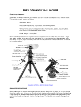
iEQ45 Assembly Term
DovetailDEC Clutch Screw
R.A. Clutch Screw
R.A. Unit
Polar Scope Cover
Alt. Locking Screw
Alt. Adjust. Knob
Azi. Locking Screw
Azi. Adjust. Knob
DEC Unit
Polar Axis Cover
DEC Axis
CW Shaft
Counterweight
CW Locking Screw
CW Safety Screw
Bubble Level Indicator
DovetailDEC Clutch Screw
R.A. Clutch Screw
R.A. Unit
Polar Scope Cover
Alt. Locking Screw
Alt. Adjust. Knob
Azi. Locking Screw
Azi. Adjust. Knob
DEC Unit
Polar Axis Cover
DEC Axis
CW Shaft
Counterweight
CW Locking Screw
CW Safety Screw
Bubble Level Indicator
Alignment Peg
Tripod Head
Tripod Support
Tripod Lock
Tripod Leg
Leg Lock Screw
Alignment Peg
Tripod Head
Tripod Support
Tripod Lock
Tripod Leg
Leg Lock Screw
September 2012, V1.10
/