Page is loading ...

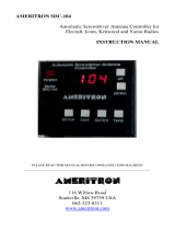
AMERITRON SDC-104
Automatic Screwdriver Antenna Controller
for
Elecraft, Icom, Kenwood and Yaesu Radios
INSTRUCTION MANUAL
PLEASE READ THIS MANUAL BEFORE OPERATING THIS MACHINE!
_______________________________________________________________________
116 Willow Road
Starkville, MS 39759 USA
662-323-8211
www.ameritron.com
Version 1C
Printed in USA

2
Introduction:
The SDC-104 Screwdriver Antenna Controller will automatically adjust the
antenna to the transceiver’s frequency. The controller reads the frequency from
an Elecraft, Icom, Kenwood or Yaesu Transceiver. The controller then moves
the antenna to the correct location. The controller connects to any Elecraft,
Kenwood or Yaesu that has an RS-232 or Icom CI-V or Yaesu TTL. The
antenna must have a sensor installed for the antenna controller to operate
properly. If your antenna does not have a sensor, contact the antenna
manufacture or Ameritron.
Features:
Automatic antenna tuning
Frequency display
Manual UP/ DOWN buttons
Adjustable current sense trip for Antenna Motor Production
Antenna turns counter
Home
Operation controls
Power: Switches the controller’s power on and off.
Up: Moves the antenna up.
DOWN: Moves the antenna down.
SETUP: Allows programming of the antenna
SKIP: Navigates thru the menus
ENTER: Stores the menu setting.
TUNE: Moves the antenna to a programmed setting for the displayed
frequency.
INSTALLATION:
1. The Red Power Line needs to be fused to protect the controller and the
antenna. The fuse must be no larger than a 5 amp rating. Some antennas may
require a lower current rating. Refer to the antenna’s manual for the current
rating. Connect the Red wire to a +12 VDC Supply. Use 16 gauge wire when
adding additional length.
2. Connect the Black wire to the negative of the power supply or chassis ground.
3. Connect the four prong Molex plug to the antenna. Note: Some antennas do
not have the correct plug to match the controller’s plug. The mate can be order
thru Ameritron part number 13-TAR102-2. Or the plug can be cut off and hard
wire to the antenna. See pictorial for wire color and its functions.
WARINGING: Do not reverse the polarity of the Red and Black wires.
Damage will occur to the controller.

3
Antennas that do not have a 4 pin plug. The plug can be cut
off. Use the chart below for wire color and its function.
CONTROL CABLE
RED MOTOR WIRE
BLACK MOTOR WIRE
GREEN SENSOR
WHITE SENSOR
WARNING: An RF choke must be placed around the control lines at
the antenna. The Controller may be damaged if an RF
choke is not used.
Motor Operating Voltage
This control unit is designed to operate with a screwdriver antenna that operates
on 12 volts. Some antennas operate on only 3 or 4 volts, a Dropping Resistor
can be used inline with the motor wires to bring the voltage down. Consult your
antenna manual or manufacturer for the operating voltage.
Important: Failure to adjust and operate your screwdriver
antenna at the proper voltage will damage the
antenna motor.
motor control

4
If a dropping resistor is necessary, a good value to try is 5 Ω/10 Watts. This
resistor will need to be placed inline on one of the motor control lines anywhere
in between the SDD-104 and the antenna. If you are not sure whether or not this
resistor is necessary for your antenna, try it and inspect the torque and speed of
the motor. If the motor is too slow, reduce or eliminate the resistance. Use of
12 volts with a 3 or 4-volt antenna will result in failure of the motor.
4. Connect the radio interface cable from the controller to the transceiver. Icom
connects to the CI-V port. Elecraft, Kenwood and Yaesu connect to the RS-232
port. A list of interface cables is listed on page 7.
The Transceiver Baud Rate must be set to 9600 bps. For Icom using CI-V port,
set CI-V address to 64, Yaesu select CAT or TTL.
WARNING: Do not apply voltages greater than 18 volts to this unit, or
permanent damage to the unit and antenna may result.
Note:
The controller will need to be programmed to the antenna before operation.
The controller reads the frequency of the transceiver and moves the antenna to
the closest programmed setting of the antenna. There can be 8 setting
programmed for each band. Some bands may only need one antenna setting
programmed to cover the whole band.
Before programming the antenna it may be necessary to move the antenna
within the band to determine how many settings need to be programmed for
each band. This can be done by pressing the power button to on and pressing
the up or down buttons after the current limit has been set properly. Refer to
setting the antenna current limit under TRIP. Before programming, the antenna
will need to be all the way to the bottom and the counter zeroed.
Programming:
1) Turn controller on. The controller will display control and the type of radio it
is programmed for. If the display is correct move to step 2. If the controller is
not displaying the correct transceiver follow the steps below.
Setting the controller to the Transceiver.
Press setup button until the display reads STORE. (5 Sec.)
Press Skip. The display will read TYPE.
Press ENTER The Display will read TS 1(This is the setting for all current
Kenwood transceivers) If this is the transceiver that you have connected press
ENTER. If not press SKIP until the correct type of transceiver is displayed then
press Enter.

5
Flow Chart: Hold SETUP for 5 seconds = STORE press SKIP= TYPE press
ENTER= TS 1 press SKIP TS 2> iCOM > FT 1 > FT 2 > ELEC. Press Enter
when the correct transceiver is displayed. Kenwood always TS1 and Yeasu FT1.
The transceiver should be displaying the transceiver’s frequency.
The display will show only the four upper digit of the frequency. Ex 14.250
displays 1425.
The controller is ready for programming the antenna to the correct location of
the Frequency being displayed.
2) Programming the Antenna.
The antenna controller has a current limit circuit for the antenna. The controller
is factory set for 1.2 amps of current. If the antenna exceeds 1.2 amps of current
the controller will turn the motor off and display TRIP.
The controller’s current limit can be changed from 100 mA to 4.9 amps at 100
mA increments. Refer to TRIP to change the current setting if the controller
continues to go into TRIP mode.
Press the down Button to move the antenna all the way down. If the down
button moves the antenna the wrong way, the motor control wires can be
swapped or the polarity can be changed in the controller’s menu. Ref to
Polarity to change the polarity to the antenna’s motor
With the antenna all the way down the controller should be displaying 0 for
turns, 0 for current and transceiver’s frequency. If the counter is not at 0 refer to
CLRP to clear the counter. It is easier to tune the highest frequency first since
the antenna is already at its lowest setting. The transceiver will need to be in
FM, RTTY or FSK during this process. Power level about 10 watts of RF.
Set the transceiver to the desired frequency for the antenna to be tuned.
The controller should display the same frequency.
1. Move the antenna up to tuned (resonant) position. This should be where the
antenna is at its lowest VSWR. Refer to the Antenna’s manual for question
about tuning the antenna.
While the antenna is moving the controller will increment between the turns
being counted, the amount of current the motor is using and the transceiver’s
frequency.
2. Store this location under Menu Store 1. To store the antenna’s tuned location
press SETUP for 5 seconds. STORE will display. Press ENTER. The display
will read the band and memory location. Example 28.5 MHZ (10 1) Press
ENTER. The location of the antenna has been stored under memory one for that
band. The controller will store up to 8 positions for each band. If another
location is need to be stored for the same band. Set the transceiver to the
frequency to be tuned. Move the antenna to the tuned position. Remember
there is already a location stored in the memory one .This location will be stored
in the memory location 2. Press SETUP for 5 seconds Store will display. Press

6
ENTER. The band and memory location will display. Press SKIP to move to
memory 2. Press ENTER. This location has been stored under memory 2.
The controller can be programmed for up to 8 positions for each band.
Repeat the steps above to program the antenna for the bands the antenna will be
used. The memory location can be over written if a change needs to be made or
a mistake is made during programming. If the antenna is not programmed for a
band it will not move to the nearest location of another band until that band has
been selected.
3) After the antenna has been programmed you will have to choose Manual
Operation or Auto Operation.
Manual Operation allows you to switch bands or move around with in the
same band with out the controller trying to move the antenna. (This is good for
searching for activity on the bands) Once the frequency has been determine
press the TUNE button. The controller will move the antenna to the closest
stored memory location.
Auto Operation The controller will move the antenna to the closest
programmed setting when the frequency or band has been changed. Note: The
antenna will be moving around a lot when searching thru the bands for activity.
Setting the Controller for Auto Operation
Press SETUP for 5 seconds or until STORE is display. Press SKIP display
will read TYPE, Press SKIP again display will read MODE.. Press ENTER
MAn will display. Press Skip to change to Auto press ENTER to store
changes.
POLARITY
The polarity of the antenna motor wires can be changed in the controllers menu.
This will prevent from having to changing the wiring to the antenna if you want
the antenna to move in the opposite direction when the up or down button is
pressed.
To change the direction of the up and down button. Press SETUP until STORE
is displayed. (5 seconds) press SKIP 3 times POL will display. Press ENTER
norn will display for normal. Press skip to change to REu. displays for reverse
Press ENTER. The controller returns back to normal operation and the up and
down buttons will be reversed.
TRIP
The controller has a current limit to help prevent the antenna’s motor from
damage. When the motor stalls the controller will turn the motor off.
The current limit can be changed in the controller’s menu under Trip. The
controller is factory set for 1.2 amps. The current limit can be changed from
100 milliamps to 4.9 amperes with 100 milliamps increments.
To set the trip current form the factory setting of 1.2 amps press SETUP until
STORED is displayed. Press SKIP 4 times TRIP will be displayed.

7
Press ENTER 12 (equals to 1200 milliamps) will be displayed. Press SKIP
until the desired setting. Press ENTER to store the setting.
INIT
Resets the antenna controller back to factory settings. This will clear all antenna
and transceiver settings.
CLRP
Clears the controller’s antenna turns counter to zero with out erasing menu
setting. If the antenna turns get off for any reason the antenna can be ran all
the way down and counter can be cleared by selecting CLRP in the menu and
pressing ENTER.
COAST
DISP
FREQ; Allows only Frequency to display and switches to turns counter when
the UP or DOWN button is press.
BOTH; Allows Frequency, Current, and Turn Count to alternate.
HOME (Auto Park)
Home mode moves the antenna down until the counter reaches zero and stops. If
the motor trip current is reach when the count is below 10 it will stop the motor
and set the counter to zero.
To enter HOME mode Press and hold the UP and DOWN buttons at the same
time until the antenna begins to move and display reads HOME.
PRE-MADE CABLES
RJ-DB9KY: Kenwood and Yaesu Transceivers with DB9 (RS-232) (serial)
RJ-8MY2: Yeasu Transceivers with mini 8 pin CAT/ LINEAR.
RJ-DB9E: Elecraft
620-8004 Icom
SDC-104I ships with a mono 3.5mm plug. Ameritron part number 620-8004
SDC-104K ships with Ameritron RJ-DB9KY Cable
SDC-104Y ships with Ameritron RJ-8MY2 Cable
SDC-104E ships with Ameritron RJ-DB9E Cable
Menu flow chart
SETUP (5 seconds) =
STORE> ENTER=band and memory location 1 press skip to go to memory location 2 and so on up
to 8. Press ENTER stores the setting under that memory location.

8
STORE>SKIP=TYPE
>ENTER=TS1>SKIP=TS2>SKIP=ICOM>SKIP=FT1>SKIP=FT2>SKIP=ELEC>ENTER=STORE
TYPE>SKIP=MODE.
>ENTER=MAN>SKIP=AUTO
MODE>SKIP=POLARITY
>ENTER=NORMAL>SKIP=REVERSE
POLARITY>SKIP=TRIP
>ENTER=Motor current shut off adjustable from 0 to 4.9 by pressing SKIP then enter to store the
setting.
TRIP>SKIP=INIT
INIT>SKIP=CLRP
OPERATION:
Move the Radio to the desired frequency,
Auto Mode: The controller reads the transceiver’s frequency and then moves
the antenna to the closest programmed setting for that frequency.
Manual Mode: The controller will read the frequency but will not move the
antenna until the Tune button is pressed.
The Up and down buttons can be used to fine tune if needed. The controller will
stay at that location until the frequency is changed or the tune button is pressed.
Trouble Shooting:
Controller does not count but antenna moves up and Down
An. 1. Check the plug for loose connection.
2, Need to determine if it is the antenna or controller.
Disconnect the antenna from the controller. Take the end of the cable going to
the controller. Press the Up or Down button and tap the two sensor pins
together. The counter will increment each time the pins are touched together
and then separated. (The up or down button must be press during the test) The
controller is good if the counter increments. It will be the antenna at fault or a
bad wire going to the antenna.
Display will note turn on.
1. Check the power lines to the controller for 12 to 15 Volts DC.
2. One of the momentary buttons could be stuck in the down position.
The controller does not read the Transceiver’s Frequency.
1. Menu is not set for the correct transceiver.
2. Check interface cable connections.
3. Check the menu of the transceiver for correct setting. (Ref. page 4)

9
The Display reads TRIP when the up or down button is pressed.
1. Trip current set too low. (Ref page 6)
2. Antenna is in a bind.
3. Relay in controller stuck.
7
8
6
5
4
3
2
1
12345678
Rear Panel View
SDC-104 PIN OUT CAT -5E EIA/TIA568B
1. GND OR/WH
2. NC ORANGE
3 RS-232 TXD GREEN / WHITE
4 RS-232 RXD BLUE
5. NC BLUE/ WHITE
6 TTL TXD GREEN
7 TTL RXD BROWN / WHTE
8 NC GROWN

10
/


