Page is loading ...

Copyright(c)2015(V2.5edition)
USER INSTRUCTION
USE/INSTALLATION
Analog HD IR
INTELLIGENT SPEED DOME CAMERA

Special Declaration
Before connecting and using this device, please read this manual carefully
and properly preserved for reference in the future.
This manual may co n tain some i n a cc u rate place in t echn o logy, or some
printing error. The contents of this man ual will up date from ti me to time , but
without notice if there is any upgrades; Update contents will be adde d in new
ve r s i o n m a n u a l . We w il l i m p r ov e or u pd a t e t h e p r o du c t o r pro g r am o f t h is
manual at any time.

- 1 -
Careful Transport
During transport, custody and install process should prevent weight, severe
vibration and soak damage to product.
Do Not Disassemble Zoom Camera
In order to well match night vision, we sell IR speed dome camera with zoom
camera, please not disassemble zoom camera if there is no technical person.
Power Supply, Video Cable and Control Cable
For power supply cable, video cable and control cable, please adopt shielded
cable and independent wiring, can not mix with other cables.
Electric Safety
Should obey all kinds of electric standard when using speed dome camera,
make sure signal cable keep enough distance(at least 50m)with high voltage
equipment or cables. If it is possible, please take lightning and surge
measurement.
Clean
When clean camera housing, please use dry soft cloth to wipe, If it is too
dirty, please use neutral cleaner to wipe lightly. Do not use strong or grind
cleaner to prevent its housing from scratching.
Strictly Sealed
Prevent liquid or other things get into speed dome housing, else it will cause
permanent damage.
Please do not use camera beyond limited temperature and humidity
Speed dome camera working temperature : -25℃ to 50℃, humidity less than
90%.
Please do not install camera near air conditioner’s outlet
Under following situation, lens will be fogged because of condensation:
*Use under the environment where the temperature rise and down
frequently which caused by the air conditioner power on and off frequently.
*Use in environment which can make glass fog.
*Use in environment full with smoke or dust.
Please do not make camera toward to strong light source, such as the sun
Toward camera to strong light source for a long time will damage the color
filter on CCD or CMOS, then it will make image lose color.
CAUTION
caution

- 2 -
CONTENTS
contents
Chapter 1 Product Overview.............................................................................3
1.1 Product features ......................................................................................3
1.2 Speed dome Parameter............................................................................3
1.3 Structure Dimension ................................................................................4
Chapter 2 Installation........................................................................................8
2.1 Install Instruction ....................................................................................8
2.2 Install Method..........................................................................................8
2.3 Baud rate Setup .....................................................................................17
2.4 Address Setup........................................................................................17
2.5 Power supply and Control cable Connection .........................................18
2.6 Connecting Method................................................................................18
2.7 Cable Mark Instruction ..........................................................................19
2.8 Typical wiring diagram...........................................................................19
Chapter 3 Basic Operation..............................................................................20
3.1 Self-test when power on .......................................................................20
3.2 Preset setup ...........................................................................................20
3.3 Call preset .............................................................................................20
3.4 Function Realization By Preset .............................................................21
3.5 Patrol Setting .........................................................................................25
Chapter 4 Appendix .........................................................................................26
4.1 FAQs .......................................................................................................26
4.2 Clean the transparent cover ..................................................................26
4.3 Lightning and Surge protection .............................................................27
4.4 RS485 bus wiring ...................................................................................28

- 3 -
Product Feature
Chapter 1 Product Overview
1.1 Product Feature
Strong Intelligent Function
• PELCO-D/P,Hikvision,Dahua and other control protocol auto diagnosis.
• 2400.4800,9600 baud rate auto diagnosis.
PTZ Control
• Using RS485 Protocol, Video Transmission Distance 500m in theory.
• Pan 0-360 degree continue rotate, tilt 0-90 degree, no monitor blind
spot.
• Support CCVC, Control Speed Dome Camera Speed. The Zoom will
auto adjust according the lens zoom
Night vision function
• Turn on the ir light according to the backlight strength.
• adjust the ir light’s brightness level according to the zoom times.
1.2 Speed dome camera parameter
Electric
Rated Voltage
Power
Consumption
Decoder Built in IR distance
100-120m
Set
Communication protocol
PELCO-D/P HIK/DAHUA
ID
1-255
Baud rate(RS485)
2400/4800/9600bps/auto identify
Operate
Pan rotate
360 endless Tilt rotate
90 degree
Preset
128
Speed
Monitor
mode Preset.
patrol,pan scan and
pattern scan
Environment
Operate
environment
Outdoor: -20℃~60℃
Indoor: -10℃~50℃
Weather-proof level
IP66
Physical
Installation mode
Wall mount/ceiling mount
environment
humidity
0-95% without
condensation
DC12V 4A±10%
10 Max at daytime, 30Max
at night(without heating)
Middle Speed:Pan 6~30 °/ S
Tilt 4~17 °/S
High Speed:Pan 0.1~200 °/S
Tilt 4~30 °/S

H tape bracket Dimension
Wall mount bracket
Ceiling mount bracket
unit:mm
57.0
255.0
48.7
63.0
∅6.
4
∅
115.0
63.0
100.0
129.0
100.0
78.5
200.0
- 4 -
1.3 Structure Dimension
Chapter 1 Product Overview
Dimension
unit:mm
H type speed dome Dimension
unit:mm
416.9
279.7
219.6 219.6
577.2

R type speed dome Dimension
214.9
243.2
150.0
150.0
231.7
Dimension
- 5 -
Chapter 1 Product Overview
R type bracket Dimension
Wall mount bracket
unit:mm
Ceiling mount bracket
unit:mm
unit:mm
20
3X
∅
4.0
∅
135.0
∅
120.0
3X∅4.0
∅135.0
∅120.0
229.0
4XΦ7.0
79.7
117.7
61.5
100.7
165.2

262.4
388.2
185.0
185.0
551.9
78.5
200.0
100.0
100.0
129.0
262.5
∅
121.
0
4
-∅
9.1
∅90.
2
- 6 -
N type speed dome Dimension
N type bracket Dimension
Wall mount bracket
Ceiling mount bracket
unit:mm
unit:mm
Dimension
Chapter 1 Product Overview

241.2
136.1
332.8
136.1
- 7 -
251.1
136.1
208.0
114.9
154.0
130.0
62.0
80.0
96.0
4x∅7.0
114.6
∅66
.
1
∅
83.7
∅3.5
124.3
3-
∅4
.
0
∅
120
.
0
29.9
30.9
∅
135
.0
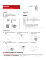
U type bracket Dimension
Wall mount bracket
Ceiling mount bracket
U type speed dome Dimension
unit:mm
unit:mm
Dimension
Chapter 1 Product Overview

Installation
63.0
∅6
.
4
∅1
15
.
0
63.0
100.0
129.0
100.0
78.5
2.1 Install Instruction
Chapter 2 Installation
Prepare before installation
In order to prevent troubles, installation should be done by professional staff
base on corresponding rules.
Confirm all spare-parts are complete, ensure application of this speed dome
camera and installation mode is suitable for requirement.
Wall/ceiling mount speed dome composite with bracket, zoom camera,
transparent cover and other parts.
- 8 -
2.2 Installation Method
Step 2-Drill holes and put expansion screws in
Drill 4pcs expansion screw's installation holes at pre-marked position, then
put 4pcs expansion screws in.(Note: please bring expansion screws own.)
Step 1-Draw positioning holes
Take out bracket from package box, mark the holes’ position based on wall
mount bracket bottom 4pcs installation holes.
Wall mount bracket
Ceiling mount bracket
H type speed dome camera installation method

- 9 -
Installation
Step 3-Unscrew 2pcs screws which
used to fixed the transparent cover for
DIP switch
Use screwdriver open 2pcs screw
which used to fix transparent cover for
DIP switch, then move transparent
cover from speed dome camera.
Step 4-Set DIP switch
Please refer to section three of this
chapter-Baud rate setup
Step 5-install transparent cover of DIP
switch
After finishing baud rate setup,
install transparent cover of DIP switch
again.
Step 6-Lead cable through bracket. Lead the cable through bracket hole.
Chapter 2 Installation
Step 7-Connect speed dome and bracket
Put speed dome camera connection port into bracket hole, screw 4pcs hexagon
screws into corresponding screw holes.

Step 8-Fix speed dome camera.
In order to get good waterproof effect, first install rubber seals on bracket, and
lead the cable out from the wiring port, then fix it on the wall/ceiling by using 4
screws. Seal the wiring port of the bracket by using silicon sealant.
Step 9-Cable Connection
Please refer to section six of this chapter-Connection method.
Chapter 2 Installation
- 1 0 -
Installation
R type speed dome camera installation method
3X∅
4.0
∅135.0
∅120.0
Wall mount bracket Ceiling mount bracket
4XΦ
7.0
79.7
117.7
61.5
100.7
Step 1-Draw positioning holes
Take out bracket from package box, mark the holes’ position based on wall mount
bracket bottom 4pcs installation holes.
Step 2-Drill holes and put expansion
screws in
Drill 4pcs expansion screw's
installation holes at pre-marked position,
then put 4pcs expansion screws in.(Note:
please bring expansion screws own.)

Installation
Chapter 2 Installation
Step 3-Unscrew 2pcs screws which used
to fixed the transparent cover for DIP
switch
Use screwdriver open 2pcs screw which
used to fix transparent cover for DIP switch,
then move transparent cover from speed
dome camera.
- 1 1 -
Step 4-Set DIP switch.
Please refer to section 3 of this
chapter-Baud rate setup.
Step 5-install transparent cover of DIP
switch.
After finishing baud rate setup, install
transparent cover of DIP switch again.
Step 6-Lead cable through wall mount bracket.
Lead the cable through wall mount bracket hole.
M4-screws
M4-screws
Step 7-Connect speed dome and wall mount bracket.
Put speed dome camera connection port into bracket hole, screw 4pcs hexagon
screws into corresponding screw holes.

- 1 2 -
Installation
Chapter 2 Installation
Step 8-Fix speed dome camera on wall.
In order to get good waterproof effect, first install rubber seals on wall mount bracket,
and lead the cable out from the wiring port, then fix it on the wall by using 4 screws.
Seal the wiring port of the bracket by using silicon sealant.
Step 9-Cable Connection
Please refer to section six of this chapter-Connection method.
Step 10-Tear off protection film
Teal off protection film of transparent cover
Note: please take care of transparent cover.
78.5
100.0
129.0
100.0
4-∅
9
.1
∅
90
.2
∅
121
.0
N type speed dome camera installation method
Wall mount bracket Ceiling mount bracket
Step 1-Draw positioning holes
Take out bracket from package box, mark the holes’ position based on wall mount
bracket bottom 4pcs installation holes.

M4 Screws
- 1 3 -
Installation
Chapter 2 Installation
Step 2-Drill holes and put expansion
screws in
Drill 4pcs expansion screw's
installation holes at pre-marked position,
then put 4pcs expansion screws in.(Note:
please bring expansion screws own.)
Step 3-Lead cable through wall mount bracket.
Lead the cable through wall mount bracket hole.
Step 4-Connect speed dome and wall mount bracket.
Put speed dome camera connection port into bracket hole, screw 4pcs hexagon
screws into corresponding screw holes.
Step 5-Fix speed dome camera on wall.
In order to get good waterproof effect, first install rubber seals on wall mount bracket,
and lead the cable out from the wiring port, then fix it on the wall by using 4 screws.
Seal the wiring port of the bracket by using silicon sealant.
M4 Screws

Installation
Chapter 2 Installation
Step 6-Cable Connection
Please refer to section six of this chapter-Connection method.
Step 7-Tear off protection film
Teal off protection film of transparent cover
Note: please take care of transparent cover.
U type speed dome camera installation method
Wall mount bracket Ceiling mount bracket
Step 1-Draw positioning holes
Take out bracket from package box, mark the holes’ position based on wall mount
bracket bottom 4pcs installation holes.
Step 2-Drill holes and put expansion screws in
Drill 4pcs expansion screw's installation holes at pre-marked position, then put
4pcs expansion screws in.
(Note: please bring expansion screws own.)
114.9
4x∅7
.
0
96.0
62.0
80.0
∅
112
.2
∅
128.0
∅
5
.2
- 1 4 -

Chapter 2 Installation
Step 3-Unscrew 2pcs screws which
used to fixed the transparent cover
for DIP switch
Use screwdriver open 2pcs screw
which used to fix transparent cover for
DIP switch, then move transparent
cover from speed dome camera.
Step 4-Set DIP switch.
Please refer to section 3 of this
chapter-Baud rate setup.
Step 5-install transparent cover of
DIP switch.
After finishing baud rate setup,
install transparent cover of DIP
switch again.
Step 6-Lead cable through wall mount bracket.
Lead the cable through wall mount bracket hole.
Installation
- 1 5 -

Chapter 2 Installation
M4 Screws
Step 7-Connect speed dome and wall mount bracket.
Put speed dome camera connection port into bracket hole, screw 4pcs hexagon
screws into corresponding screw holes.
Step 8-Fix speed dome camera on wall.
In order to get good waterproof effect, first install rubber seals on wall mount bracket,
and lead the cable out from the wiring port, then fix it on the wall by using 4 screws.
Seal the wiring port of the bracket by using silicon sealant.
Step 9-Cable Connection
Please refer to section six of this chapter-Connection method.
Step 10-Tear off protection film
Teal off protection film of transparent cover
Note: please take care of transparent cover.
Installation
- 1 6 -
M4 Screws

ONOFF OFF OFF OFF OFF OFF
OFF
ONON OFF OFF OFF OFF OFF
OFF
2
3
2.3 Baud Rate Setup
SW1-1 SW1-2
SW1-3
SW1-4 SW1-5 SW1-6 SW1-7
SW1-8
ON OFF OFF OFF OFF OFF OFF
OFF
1
SW1 Switch Setup
Address
1 2 3 4 5 6 7 8
ON
ID setup (address code setup obey binary rules)
address code shall be set through 8 DIP switch (SW1).
Keyboard control speed dome through communication
bus, one keyboard can control max. 255pcs speed dome camera, each speed
dome camera has its own address code, user can set address code through 8
DIP switch, details as bellow:
2.4 ID Setup
Chapter 2 Installation
2400bps 4800bps 9600bps
Baud rate and corresponding DIP status as bellow:
1 2
ON
1 2
ON
1 2
ON
1 2
ON
Baud Rate
Automatic identify
Rs485 control bus need all device which connect to it shall be in parallel mode, and
each end of the system shall be connected to a 120ohm resistor. Our speed dome has
a 120ohm resistor in it, you need only set it up through dip switch SW2, put the 4th
switch on, then the resistor is connected, details as below:
ON
1 2 3 4
resistor is connected
ON
1 2 3 4
resistor isn’t connected
Installation
- 1 7 -

OFFOFF ON OFF OFF OFF OFF
OFF
ON OFF ON OFF OFF OFF OFF
OFF
ONOFF ON OFF OFF OFF OFF
OFF
OFFOFF OFF
ON
OFF OFF OFF
OFF
ONON ON OFF OFF OFF OFF
OFF
4
5
6
7
8
ONON OFF ON OFF OFF OFF
OFF
11
- - -- - - - - - - - - - - - - - - - - - - - -
ON
ON ON
ON
ON ON ON ON
ON
OFF ON
ON
ON ON ON ON
- - -
254
255
OFFOFF ON ON OFF OFF OFF OFF
12
Note: Please check rated voltage and power supply carefully, rated voltage
and current as bellow:
rated voltage range
current
rated voltage
Control line connection
Connect RS485 line to keyboard controller or DVR, if there are more than one need to
be controlled by keyboard or DVR, please connect it in parallel.
Note: (1) protocol and baud rate of keyboard and DVR can be set by customer, just
make sure it is same with that of speed dome.
(2) the ID of different speed dome which is in same system shall be set as different.
(3)It should set the difference PTZ Camera Address in Monitor system with multi
cameras.
2.5 Power supply and control cable connection
Power supply connection
2.6 Connection Method
Connection method as bellow diagram, connect video cable, control cable, power
supply cable in turn. Connection method of keyboard can refer to keyboard manual
(connection cable order based on keyboard model, here only provide one possible
example), please refer to bellow diagram for detail.
- 1 8 -
Chapter 2 Installation
ON OFF
OFF
ON OFF OFF OFF
OFF
ONOFF OFF ON OFF OFF OFF
OFF
9
10
±10%
4A
H/N:DC12V ( AC 24V Optional)
±10%
2A
R/U:DC12V
Installation
Note: Due to the N dome camera not dial the code switch,N address by enabling
software to set up.
/