Page is loading ...

User’s Manual
Rev K
May 2015
User’s Manual
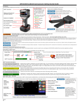
475 Field Communicator

Read this User’s Manual before working with the 475 Field
Communicator. For personal and system safety, and for
optimum product performance, thoroughly understand the
contents before using or servicing this product.
For equipment service needs, cont
act the nearest product
representative.
475 FIELD COMMUNICATOR
www.fieldcommunicator.com
475 Field Communicator
©Emerson Process Management. 2015. All rights reserved.
The Emerson logo is a trademark and ser
vice mark of Emerson Electric
Co.
AMS, DeltaV, and ValveLink
are marks of one of the Emerson group of
companies.
Windows is a registered trademark of Microsoft Corporation in the United
S
tates and other countries.
IrDA is a registered trademark of the Infrared D
ata Association.
Bluetooth is a registered trademark of the Bluetooth SIG, Inc.
F
OUNDATION is a trademark of the Fieldbus Foundation of Austin, Texas,
USA.
HART and WirelessHART are registered trademarks of the HART
Com
munication Foundation of Austin, Texas, USA.
Hitachi is a registered trademark of Hitachi America, Ltd.
All other marks are property of th
eir respective owners.
NOTICE

www.fieldcommunicator.com
475 FIELD COMMUNICATOR
TABLE OF CONTENTS
SECTION 1
Introduction
Using this manual. . . . . . . . . . . . . . . . . . . . . . . . . . . . . . . . 7
SECTION 2
Learning the basics
Overview . . . . . . . . . . . . . . . . . . . . . . . . . . . . . . . . . . . . . . . 9
Safety messages . . . . . . . . . . . . . . . . . . . . . . . . . . . . . . . . 9
475 Field Communicator overview . . . . . . . . . . . . . . . . . 10
Device interoperability. . . . . . . . . . . . . . . . . . . . . . . . . . . 10
Working in a hazardous area . . . . . . . . . . . . . . . . . . . . . 11
Battery and
power supply/charger . . . . . . . . . . . . . . . . . . . . . . . . . . . 11
Using the touch screen . . . . . . . . . . . . . . . . . . . . . . . . . . 16
Using the keypad . . . . . . . . . . . . . . . . . . . . . . . . . . . . . . 16
Memory . . . . . . . . . . . . . . . . . . . . . . . . . . . . . . . . . . . . . . 18
Accessories. . . . . . . . . . . . . . . . . . . . . . . . . . . . . . . . . . . 19
Assembly. . . . . . . . . . . . . . . . . . . . . . . . . . . . . . . . . . . . . . 21
Installing the System Card and the battery . . . . . . . . . . . 21
Removing the battery and the System Card . . . . . . . . . . 22
Starting up and shutting down . . . . . . . . . . . . . . . . . . . . 22
Starting up. . . . . . . . . . . . . . . . . . . . . . . . . . . . . . . . . . . . 22
The Field Communicator Main Menu . . . . . . . . . . . . . . . 22
Entering standby . . . . . . . . . . . . . . . . . . . . . . . . . . . . . . . 23
Shutting down . . . . . . . . . . . . . . . . . . . . . . . . . . . . . . . . . 23
Settings . . . . . . . . . . . . . . . . . . . . . . . . . . . . . . . . . . . . . . . 24
About. . . . . . . . . . . . . . . . . . . . . . . . . . . . . . . . . . . . . . . . 24
Backlight . . . . . . . . . . . . . . . . . . . . . . . . . . . . . . . . . . . . . 24
Clock . . . . . . . . . . . . . . . . . . . . . . . . . . . . . . . . . . . . . . . . 24
Contrast . . . . . . . . . . . . . . . . . . . . . . . . . . . . . . . . . . . . . 25
Licenses . . . . . . . . . . . . . . . . . . . . . . . . . . . . . . . . . . . . . 25
Power . . . . . . . . . . . . . . . . . . . . . . . . . . . . . . . . . . . . . . . 25
Power Button . . . . . . . . . . . . . . . . . . . . . . . . . . . . . . . . . 26
Retrain Battery . . . . . . . . . . . . . . . . . . . . . . . . . . . . . . . . 26
Touch Screen . . . . . . . . . . . . . . . . . . . . . . . . . . . . . . . . . 26
Event Capture . . . . . . . . . . . . . . . . . . . . . . . . . . . . . . . . . 27
Memory . . . . . . . . . . . . . . . . . . . . . . . . . . . . . . . . . . . . . . 27
Connecting to a device . . . . . . . . . . . . . . . . . . . . . . . . . . 28
PC applications. . . . . . . . . . . . . . . . . . . . . . . . . . . . . . . . . 28
AMS Device Manager . . . . . . . . . . . . . . . . . . . . . . . . . . . 28
Field Communicator Easy Upgrade Utility . . . . . . . . . . . 28
Connecting the 475 Field Communicator or System Card29
Upgrading the 475 Field Communicator . . . . . . . . . . . . . 33

Table of Contents
4
Adding functionality by enabling licenses . . . . . . . . . . . . 33
ScratchPad . . . . . . . . . . . . . . . . . . . . . . . . . . . . . . . . . . . . 34
Creating a new document . . . . . . . . . . . . . . . . . . . . . . . . 35
Opening an existing document . . . . . . . . . . . . . . . . . . . . 35
ValveLink Mobile . . . . . . . . . . . . . . . . . . . . . . . . . . . . . . . 37
Maintenance . . . . . . . . . . . . . . . . . . . . . . . . . . . . . . . . . . . 37
Running a self test . . . . . . . . . . . . . . . . . . . . . . . . . . . . . 37
Calibrating. . . . . . . . . . . . . . . . . . . . . . . . . . . . . . . . . . . . 37
SECTION 3
HART functionality
Overview . . . . . . . . . . . . . . . . . . . . . . . . . . . . . . . . . . . . . . 39
Safety messages . . . . . . . . . . . . . . . . . . . . . . . . . . . . . . . 39
Basic features and functions . . . . . . . . . . . . . . . . . . . . . 40
HART Application functionality . . . . . . . . . . . . . . . . . . . . 40
Using a fast key sequence . . . . . . . . . . . . . . . . . . . . . . . 40
Starting the HART Application . . . . . . . . . . . . . . . . . . . . 40
Working with offline configurations . . . . . . . . . . . . . . . . 41
Creating a new configuration . . . . . . . . . . . . . . . . . . . . . 41
Opening a saved configuration . . . . . . . . . . . . . . . . . . . . 42
Transferring configurations to a PC application . . . . . . . 44
Working online with HART devices . . . . . . . . . . . . . . . . 45
Connecting to a HART device. . . . . . . . . . . . . . . . . . . . . 45
Displaying the connected HART devices . . . . . . . . . . . . 48
The HART icon . . . . . . . . . . . . . . . . . . . . . . . . . . . . . . . . 49
Saving a device configuration . . . . . . . . . . . . . . . . . . . . . 49
Displaying Device Setup options . . . . . . . . . . . . . . . . . . 50
Displaying Graphics . . . . . . . . . . . . . . . . . . . . . . . . . . . . 51
Configuring the HART Application . . . . . . . . . . . . . . . . . 52
Using hot keys . . . . . . . . . . . . . . . . . . . . . . . . . . . . . . . . 52
Changing the HART polling options . . . . . . . . . . . . . . . . 53
Ignoring status messages . . . . . . . . . . . . . . . . . . . . . . . . 55
Displaying the HART short tag or long tag in a menu title 55
Storage Cleanup . . . . . . . . . . . . . . . . . . . . . . . . . . . . . . . 55
Viewing available device descriptions. . . . . . . . . . . . . . . 56
Simulating an online connection to a HART device . . . . 56
Running HART diagnostics . . . . . . . . . . . . . . . . . . . . . . . 57
DC voltage measurement (HART terminals) . . . . . . . . . 57
Disconnecting from a HART device . . . . . . . . . . . . . . . . 57
SECTION 4
Fieldbus functionality
Overview . . . . . . . . . . . . . . . . . . . . . . . . . . . . . . . . . . . . . . 59
Safety messages . . . . . . . . . . . . . . . . . . . . . . . . . . . . . . . 59
Basic features and functions . . . . . . . . . . . . . . . . . . . . . 60
Fieldbus Application functionality . . . . . . . . . . . . . . . . . . 60
Link Active Scheduler (LAS) . . . . . . . . . . . . . . . . . . . . . . 60
LAS hierarchy . . . . . . . . . . . . . . . . . . . . . . . . . . . . . . . . . 60

Table of Contents
5
Starting the Fieldbus Application . . . . . . . . . . . . . . . . . . 61
Working online with fieldbus devices . . . . . . . . . . . . . . 61
Connecting to a fieldbus device . . . . . . . . . . . . . . . . . . . 62
Displaying the connected fieldbus devices . . . . . . . . . . . 65
Displaying the online device . . . . . . . . . . . . . . . . . . . . . . 66
Block modes . . . . . . . . . . . . . . . . . . . . . . . . . . . . . . . . . . 66
Device blocks . . . . . . . . . . . . . . . . . . . . . . . . . . . . . . . . . 69
Displaying Graphics . . . . . . . . . . . . . . . . . . . . . . . . . . . . 75
Configuring the Fieldbus Application . . . . . . . . . . . . . . 75
Changing the fieldbus polling addresses . . . . . . . . . . . . 75
Changing the Slot Time . . . . . . . . . . . . . . . . . . . . . . . . . 76
Viewing available device descriptions. . . . . . . . . . . . . . . 76
Running fieldbus diagnostics . . . . . . . . . . . . . . . . . . . . . 77
DC voltage measurement . . . . . . . . . . . . . . . . . . . . . . . . 77
Noise level measurement . . . . . . . . . . . . . . . . . . . . . . . . 77
Signal level measurement. . . . . . . . . . . . . . . . . . . . . . . . 77
Disconnecting from a fieldbus device . . . . . . . . . . . . . . 78
SECTION 5
Troubleshooting
Overview . . . . . . . . . . . . . . . . . . . . . . . . . . . . . . . . . . . . . . 79
Troubleshooting suggestions . . . . . . . . . . . . . . . . . . . . . 79
Error and status messages . . . . . . . . . . . . . . . . . . . . . . . 84
Information for Technical Support . . . . . . . . . . . . . . . . . 90
APPENDIX A
Reference data
Processor and memory specifications. . . . . . . . . . . . . . 91
Microprocessor . . . . . . . . . . . . . . . . . . . . . . . . . . . . . . . . 91
Memory . . . . . . . . . . . . . . . . . . . . . . . . . . . . . . . . . . . . . . 91
Physical specifications . . . . . . . . . . . . . . . . . . . . . . . . . . 91
Weight. . . . . . . . . . . . . . . . . . . . . . . . . . . . . . . . . . . . . . . 91
Display . . . . . . . . . . . . . . . . . . . . . . . . . . . . . . . . . . . . . . 91
Keypad . . . . . . . . . . . . . . . . . . . . . . . . . . . . . . . . . . . . . . 91
Usage specifications . . . . . . . . . . . . . . . . . . . . . . . . . . . . 92
Temperature limits . . . . . . . . . . . . . . . . . . . . . . . . . . . . . 92
Storage with batteries . . . . . . . . . . . . . . . . . . . . . . . . . . . 92
Storage without batteries . . . . . . . . . . . . . . . . . . . . . . . . 92
Enclosure rating . . . . . . . . . . . . . . . . . . . . . . . . . . . . . . . 92
Shock . . . . . . . . . . . . . . . . . . . . . . . . . . . . . . . . . . . . . . . 92
General guidelines . . . . . . . . . . . . . . . . . . . . . . . . . . . . . 92
Connection specifications. . . . . . . . . . . . . . . . . . . . . . . . 92
HART and fieldbus communication terminals . . . . . . . . . 92
Connection types . . . . . . . . . . . . . . . . . . . . . . . . . . . . . . 92
Battery specifications . . . . . . . . . . . . . . . . . . . . . . . . . . . 93
Battery type. . . . . . . . . . . . . . . . . . . . . . . . . . . . . . . . . . . 93
Connection . . . . . . . . . . . . . . . . . . . . . . . . . . . . . . . . . . . 93
Charge . . . . . . . . . . . . . . . . . . . . . . . . . . . . . . . . . . . . . . 93

Table of Contents
6
Lights . . . . . . . . . . . . . . . . . . . . . . . . . . . . . . . . . . . . . . . 93
Operating time . . . . . . . . . . . . . . . . . . . . . . . . . . . . . . . . 93
Storage . . . . . . . . . . . . . . . . . . . . . . . . . . . . . . . . . . . . . . 93
Power supply/charger specifications. . . . . . . . . . . . . . . 94
Connection . . . . . . . . . . . . . . . . . . . . . . . . . . . . . . . . . . . 94
Lights . . . . . . . . . . . . . . . . . . . . . . . . . . . . . . . . . . . . . . . 94
Voltage . . . . . . . . . . . . . . . . . . . . . . . . . . . . . . . . . . . . . . 94
Technical data. . . . . . . . . . . . . . . . . . . . . . . . . . . . . . . . . 94
Order information. . . . . . . . . . . . . . . . . . . . . . . . . . . . . . . 95
Spare parts list . . . . . . . . . . . . . . . . . . . . . . . . . . . . . . . . . 97
APPENDIX B
Product certifications
Overview . . . . . . . . . . . . . . . . . . . . . . . . . . . . . . . . . . . . . . 99
Approved Manufacturing Locations . . . . . . . . . . . . . . . . 99
FCC . . . . . . . . . . . . . . . . . . . . . . . . . . . . . . . . . . . . . . . . . . 99
IC . . . . . . . . . . . . . . . . . . . . . . . . . . . . . . . . . . . . . . . . . . . . 99
Telecommunications Regulatory Authority. . . . . . . . . 100
European Directive Information - CE Compliance . . . 100
R&TTE (1999/5/EC) . . . . . . . . . . . . . . . . . . . . . . . . . . . 100
Electro Magnetic Compatibility (2004/108/EC) . . . . . . . 100
Low Voltage (2006/95/EC) . . . . . . . . . . . . . . . . . . . . . . 100
ATEX Directive (94/9/EC) (KL option only) . . . . . . . . . . 100
Hazardous Locations Certifications (KL option only). 100
European Certifications. . . . . . . . . . . . . . . . . . . . . . . . . 100
International Certification . . . . . . . . . . . . . . . . . . . . . . . 101
North American Certifications . . . . . . . . . . . . . . . . . . . . 101
Power Supply/Charger Certification. . . . . . . . . . . . . . . 102
Declaration of Conformity/Approvals . . . . . . . . . . . . . . 102
Label Drawings. . . . . . . . . . . . . . . . . . . . . . . . . . . . . . . . 102
Approval Drawings. . . . . . . . . . . . . . . . . . . . . . . . . . . . . 106
APPENDIX C
Graphics information
Overview . . . . . . . . . . . . . . . . . . . . . . . . . . . . . . . . . . . . . 111
Screen layout . . . . . . . . . . . . . . . . . . . . . . . . . . . . . . . . . 111
Buttons . . . . . . . . . . . . . . . . . . . . . . . . . . . . . . . . . . . . . . 112
Graphics options . . . . . . . . . . . . . . . . . . . . . . . . . . . . . . 112
Images . . . . . . . . . . . . . . . . . . . . . . . . . . . . . . . . . . . . . 112
Charts . . . . . . . . . . . . . . . . . . . . . . . . . . . . . . . . . . . . . . 113
Graphs . . . . . . . . . . . . . . . . . . . . . . . . . . . . . . . . . . . . . 116
Glossary . . . . . . . . . . . . . . . . . . . . . . . . . . . . . . . . . . . G-117
Index . . . . . . . . . . . . . . . . . . . . . . . . . . . . . . . . . . . I-125

www.fieldcommunicator.com
475 FIELD COMMUNICATOR
SECTION 1INTRODUCTION
USING THIS MANUAL The sections in this manual provide the following information on the
475 Field Communicator.
Section 2: Learning the basics contains information on assembly,
components, starting, entering standby, shutting down, settings,
supported PC applications, and maintaining the 475 Field
Communicator.
Section 3: HART functionality contains information on starting and
configuring the HART
®
Application, working offline, communicating
with HART devices, modifying device parameters, and running
diagnostics.
Section 4: Fieldbus functionality contains information on starting
and configuring the Fieldbus Application, communicating with fieldbus
devices, modifying device parameters, and running diagnostics.
Section 5: Troubleshooting provides solutions to the most common
475 Field Communicator operating problems.
Appendix A: Reference data provides physical, functional, and
performance specifications.
Appendix B: Product certifications contains hazardous location
and international certifications, European directive information, and
approval drawings.
Appendix C: Graphics information contains an overview of the
Graphics functionality and options in the 475 Field Communicator.

Introduction
8

www.fieldcommunicator.com
475 FIELD COMMUNICATOR
SECTION 2LEARNING THE BASICS
OVERVIEW This section provides instructions on basic features and functions of
the 475 Field Communicator. It also provides information on assembly,
components, starting, entering standby, shutting down, settings,
applications, and maintaining the 475 Field Communicator. The
functionality described in this section is based on system software
version 3.9.
SAFETY MESSAGES Procedures and instructions in this section may require special
precautions to ensure the safety of the personnel performing the
operation. Information that raises potential safety issues is indicated by
a warning symbol (
). Refer to the safety messages before
performing an operation preceded by this symbo
l. See the
“Troubleshooting” section for more warning messages.
This equipment has been tested and found to comply with the
limits for a Class A digital device, pursuant to part 15 of the FCC
Rules. These limits are designed to provide reasonable protection
against harmful interference when the equipment is operated in a
commercial environment. This equipment generates, uses, and
can radiate radio frequency energy and, if not installed and used in
accordance with the user’s manual, may cause harmful
interference to radio communications. Operation of this equipment
in a residential area is likely to cause harmful interference in which
case the user will be required to correct the interference at his own
expense.
This device complies with Part 15 of the FCC Rules. Operation is
sub
ject to the following two conditions: (1) this device may not
cause harmful interference, and (2) this device must accept any
interference received, including interference that may cause
undesired operation.
Any modifications made to this device
that are not approved by
Emerson Process Management may void the authority granted to
the user by the FCC to operate this equipment.
This Class A digital apparatus complies with Canadian ICES-003.
IMPORTANT NOTICE

You can install or remove the Lithium Ion (Li-Ion) battery (Power
Module) in a hazardous area environment.You cannot charge the
battery in this environment because the power supply/charger
(00375-0003-0005) is not IS-approved.
Learning the basics
10
475 FIELD
COMMUNICATOR
OVERVIEW
The 475 Field Communicator supports HART and FOUNDATION fieldbus
devices, letting you configure, maintain, or troubleshoot devices. When
using the 475 Field Communicator to communicate with devices,
follow all standards and procedures applicable to the location. Failure
to comply may result in equipment damage and/or personal injury. Be
sure to understand and comply with the sections in this manual.
The 475 Field Communicator includes a color LCD touch screen, a
Li-Ion batte
ry (Power Module), a SH3 processor, memory components,
System Card, and integral communication and measurement circuitry.
The Field Communicator also supports multiple languages. See the
rea
dme file included with the Field Communicator Easy Upgrade Utility
or www.fieldcommunicator.com for more information.
Device interoperability The 475 Field Communicator is designed to operate with a wide range
of HART and F
OUNDATION fieldbus devices independent of device
manufacturer. Device interoperability is achieved through the
Electronic Device Description Language (EDDL) technology supported
by the HART Communication Foundation and Fieldbus Foundation.
Basic testing is performed on all de
vice descriptions. Each device
manufacturer is asked to certify that they thoroughly tested their
devices with the 475 Field Communicator. If certification is not
received, a warning message displays when you attempt to
communicate with an untested device. New device descriptions are
available from the Field Communicator Easy Upgrade Utility or the
Resource CD or DVD.
WARNING

Learning the basics
11
Working in a hazardous
area
A 475 Field Communicator that meets the Intrinsic Safety requirements
(I/S-approved) can be used in Zone 0 (FM), Zone 1, or Zone 2, for
Group IIC, and Class I, Division 1 and Division 2, Groups A, B, C, and
D locations.
An IS-approved 475 Field Communicator may be connected to loops
or segment
s that are attached to equipment located in Zone 0, Zone 1,
Zone 2, for Group IIC; Zone 20, Zone 21, Zone 22, and Class I,
Division 1 and Division 2, Groups A, B, C, and D locations.
IS-approved 475 Field Communicators are ordered with the KL option
and
have an additional label on the back of the 475 that lists the
approvals.
See Appendix B “Product certifications” for more information about IS
approvals and installations.
CAUTION
You can install or remove the Li-Ion battery in a hazardous area
environment. You cannot charge the battery in this environment
because the power supply/charger is not IS-approved.
Battery and
power supply/charger
The 475 Field Communicator is powered by a Li-Ion battery that has a
green, 6-pin connector. The power supply/charger also has a green
connector to match the appropriate connector on the battery. See
Figure 2-1 for the location of the connector.
Prior to using the 475 Field Communicato
r without the power
supply/charger connected, fully charge the battery.
Guidelines and precautions
Understand and follow the guidelines and precautions below before
using
the battery or power supply/charger.
• When transporting a Li-Ion battery, follow all applicable regulations.
• Protect the battery and power supply/charger from moisture, and
respect opera
ting and storage temperature limits. See Appendix A
“Reference data” for more information.
• Do not cover the battery or power supply/charger, subject it to
prolonge
d periods of direct sunlight, or place it upon or next to
heat-sensitive materials.
• Charge the battery with only the Field Communicator power
supply/ch
arger. The power supply/charger should not be used with
other products. Failure to comply may permanently damage your
475 Field Communicator and will void the IS approval and the
warranty.
• Do not open or modify the battery or power supply/charge
r. There
are no user-serviceable components or safety elements inside.
Opening or modifying them will void the warranty and could cause
personal harm.

Learning the basics
12
Checking the remaining charge
To view the remaining charge, press the Charge Indicator button on
the
lower left side of the battery. See Figure 2-1 for the location of this
button. When you press and release the button, the lights above the
but
ton slowly illuminate to display the charge remaining. Each light
represents 20 percent of the charge. The battery is fully charged when
all of the lights are illuminated.
You can also check the remaining charge fr
om the Settings menu on
the Field Communicator Main Menu. See “Power” on page 25 for more
information.
Figure 2-1. Li-Ion battery example
Charge Indicator button
Lights illuminated by pressing the Charge
Indicator button
Li-Ion
battery
Green power supply/charger connector (side)
Charging the battery
Prior to first portable use, fully charge the battery. The battery can be
charged
separately or while attached to the 475 Field Communicator.
The 475 Field Communicator is fully operable while the battery is
recharging, and a full charge takes 2-3 hours. An overcharge condition
will not occur if the power supply/charger remains connected.
CAUTION
You can remove and install the Li-Ion battery in a hazardous area
environment. You cannot charge the battery in this environment
because the power supply/charger is not IS-approved.

Learning the basics
13
To charge the battery:
1.Plug the power supply/charger into a power outlet.
2.Plug the green power supply/charger connector into the green
connector on
the battery. The flat side of the power supply/charger
connector should face the front of the 475 or the inside of the battery,
if the battery is not attached to the 475. The battery is fully charged
when the light on the power supply/charger is green.
Figure 2-2. Charging the battery connected to the 475 Field
Communicato
r
Power supply/charger
connector
Power supply/charger
Power supply/charger lights

Learning the basics
14
Power supply/charger lights
Three lights are on the power supply/charger to indicate the conditions
below. Each light displays a different color.
Table 2-1. Power supply/charger lights
Maintaining the battery
To help maintain the performance and life of the Li-Ion battery,
understand and follow the guidelines below:
• Recharge the battery frequently, preferably after each use or at
night. Limit the number of full discharges, if possible.
• Frequent use at high temperatures can reduce performance.
• Use a dry location at or near room temperature when storing the
battery for an extended time. Prolonged storage at higher
temperatures can reduce performance.
• Ensure the remaining charge level is at or near mid-capacity when
storing for an extended time. The remaining charge will slowly drain
during storage. Periodically charge the battery to ensure the
remaining charge does not drain to low levels.
Color Condition
Green The battery is fully charged.
Flashing green The battery is nearly fully charged.
Yellow The battery is charging.
Flashing yellow The power supply/charger is not connected to
the 475 Field Communicator.
Flashing yellow and
red
The remaining charge in the battery is very low.
Red Charging cannot occur. Contact Technical
Support for more information.

Learning the basics
15
Figure 2-3. 475 Field Communicator shown with optional rubber boot
IrDA
®
interface
(top)
Tab key
Navigation keys
(four arrow keys)
HART and F
OUNDATION fieldbus
communication terminals (top)
Enter key
Function key and
light (for multiple-key
combination
functionality)
Alphanumeric
keypad
Backlight key
Green power
supply/charger
connector on the
battery
(side)
Li-Ion battery (back) and
System Card (internal)
Stylus (in the strap)
Bluetooth
®
light
Strap attachment
(side)
Strap attachment (side)
Strap attachment (side)
Touch screen display
Strap attachment
(side)
Power key and light
Charge Indicator button
(side)
Lights illuminated by
pressing the
Charge Indicator button
(side)

Learning the basics
16
Using the touch screen The touch screen and keypad let you select menu items and enter text.
Use the provided stylus or the up and down arrow keys on the keypad
to select a menu item. On the Settings and Field Communicator Main
Menu, tap an icon or press Enter to open the selected icon. On other
menus, double-tap the selected item on the screen or press the right
arrow key on the keypad to open a menu item.
CAUTION
Contact the touch screen with blunt items only, preferably the stylus
included with the 475 Field Communicator. See Figure 2-3 on page 15
for the location of the stylus. Sharp instruments, such as screwdrivers,
can damage
the touch screen. Repairing the touch screen requires
replacement of the entire display assembly, which is possible only at
an authorized service center.
Use the back arrow icon ( ) on the window to return to the previous
menu. Use the close icon (
) in the upper right corner of the window
to end the application.
If the touch screen seems inaccurate, you can recalibrate it. For more
in
formation, see “Touch Screen” on page 26.
NOTE
All instructions in this manual are written for the touch screen.
Use the soft input panel (SIP) keyboard
The SIP keyboard allows for alphanumeric input using the touch
screen
. The SIP keyboard detects when you need to enter characters
and appears automatically as required.
Using the keypad The following section describes the buttons on the 475 Field
Communicator keypad.
Bluetooth symbol (
)
The Bluetooth symbol on the keypad is illuminated
by a blue light when
Bluetooth is enabled from the Listen for PC window. The 475 Field
Communicator must be licensed for Bluetooth to use this functionality.
Power key
The Power key is used to power on and off the 475 Field
Communicato
r or to put it in standby. You can set the default option,
stand by or shut down, from the Settings menu. See “Power Button” on
page 26 for more information. The green light on the Power key
flashes when you press and hold the Power key to turn on the 475
Field Commun
icator. The light is constant when the 475 is on, and it
slowly blinks when the 475 is in standby.

Learning the basics
17
If the Power key is pressed when there is unsent data or a device
method is running, a warning message appears. Tap OK to have the
475 Field Communicator enter standby or shut down, or tap Cancel to
return to the previous window.
The Power key is disabled when the 475 Field Communicator is in
Listen for PC mode or when the ScratchPad application is open.
Arrow navigation keys
Four arrow navigation keys let you move through the menus and icons
in the applications. Press the up and down arrow keys to select a
menu item. On the Settings and Field Communicator Main Menu, tap
an icon or press the Enter key to open the selected menu. On all other
menus, use the right arrow key to open a menu item or the left arrow
key to return to the previous menu.
The blue text near the keys indicates alternate functionality that can be
enabled by pressing the Function key.
Enter key
The Enter key lets you open the selected (highlighted) button on a
window or an icon on the Field Communicator Main Menu or Settings
Menu. For example, if you push the Enter key when the Cancel button
on a window is selected, you will close that window.
Tab key
The Tab key lets you move between selectable controls on a window.
Pressing the Tab key selects the icons from left to right across all of the
rows on the screen.
Alphanumeric keypad
The alphanumeric keypad lets you enter letters, digits, and other
characters, such as punctuation marks. The 475 Field Communicator
automatically determines which text options are available depending
upon the input necessary for the particular field.
To enter text when in alphanumeric mode, press the desired keypad
button in quick repetition to scroll through the options to display the
appropriate letter or number. For example, to type the letter Z, press
the 9 key quickly four times.
The blue text near the keys indicates alternate functionality that can be
enabled by pressing the Function key. The alternate function on the
alphanumeric 5 key (insert) will be activated in future releases of the
475 Field Communicator software.

Learning the basics
18
Backlight key
The Backlight key lets you adjust the intensity of the touch screen
display. There are four different settings. The intensity impacts the
charge in the battery. Expect a shorter charge life for higher intensities.
See
“Backlight” on page 24 for information on timers that can turn off
the backlight after specified periods of inactivity. These timers can help
conserve the battery power.
Function (Fn) key
The Function key lets you enable alternate functionality on select keys.
The Function key does not apply for menus displaying icons.The blue
text near the other keys on the keypad indicate the alternate
functionality. When the Function key is enabled, the orange light in the
left corner of the Function key appears and the FN button on the Soft
Input Panel (SIP), if displayed, is highlighted. Press the Function key
again to disable the functionality and turn off the light.
Memory Types
The 475 Field Communicator memory consists of three components:
1.Internal Flash—32MB non-volatile RAM. The Internal Flash memory
stores the operating system and system software. It also stores the
following:
• Up to 25 HART configurations
• HART Event Captures
•FOUNDATION fieldbus statistics
• Text files saved from ScratchPad
2.System Card—an internal 1 GB or higher Secure Digital Card with
non-volatile flash memory. A copy of installable system software
exists on every System Card. The System Card also contains all
HART and F
OUNDATION fieldbus device descriptions and can store
up to 1,000 HART configurations, depending on the sizes of the files.
3.RAM—32MB used only for program execution.
Available memory space
To view the available memory in your 475 Field Communicator,
connect to the Field Communicator Easy Upgrade Utility or tap the
Memory icon from the Settings menu. The Field Communicator Main
Menu displays the Settings menu item. See
“Memory” on page 27 for
more information.
Free memory on the System Card
Over time, your System Card may become full and unable to store new
files. To free memory on your System Card, use the Memory
Management feature in the Field Communicator Easy Upgrade Utility.
This lets you filter and select which device descriptions can be
transferred onto your System Card. Device descriptions from selected
manufacturers or protocols are omitted during an upgrade, allowing
more space for other files.

Learning the basics
19
If the selected device descriptions are already on your 475, they are
removed the next time you connect the 475 Field Communicator to the
Easy Upgrade Utility. You are prompted before the files are removed.
See the Easy Upgrade Utility Help for more information.
Accessories Rubber boot
A rubber boot can be purchased to further protect your 475 Field
Communicato
r. The boot has an additional stand on the back, cut outs
for the straps, and holders for the stylus. An anti-static material is used
to meet the applicable Intrinsic Safety requirements.
Figure 2-4.
Back of the 475 Field Communicator Rubber Boot

Learning the basics
20
Straps
Two straps are available with the 475 Field Communicator. The
magnetic stra
p attaches to the top of the 475 Field Communicator and
lets you hang it from a metal pipe. The strap attachment is located near
the HART and fieldbus terminals on the top of the 475 Field
Communicator.
The side strap lets you attach a strap to the sides or back of the 475
Field
Communicator, making it easy to carry. See Figure 2-5. The side
strap also holds the stylus used with the touch screen.
Figure 2-5. Side Strap Example
/