Matrix A3x-04 Owner's manual
- Type
- Owner's manual

ALB7xi ALB5x
ALB7xe ALB3x
E7xi E5x
E7xe E3x
A7xi A5x
A7xe A3x

2
3 IMPORTANT PRECAUTIONS
5 ASSEMBLY
12 BEFORE YOU BEGIN
14 MAINTENANCE
15 PRODUCT SPECIFICATIONS

3
IMPORTANT PRECAUTIONS
SAVE THESE INSTRUCTIONS
• When using an Ascent Trainer or Suspension Elliptical Trainer, basic precautions should always be followed, including the following: Read all instructions before using
this equipment. It is the responsibility of the owner to ensure that all users of this equipment are adequately informed of all warnings and precautions.
• This equipment is intended for commercial use. To ensure your safety and protect the equipment, read all instructions before operating.
DANGER!
TO REDUCE THE RISK OF ELECTRICAL SHOCK:
• Always unplug the equipment from the electrical outlet immediately after using, before cleaning, performing maintenance and putting on or taking off parts.
• Care should be taken when mounting or dismounting the
equipment. Before mounting or dismounting, move the
pedal on the mounting or dismounting side to its lowest
position and bring the machine to a complete stop.
• To maintain balance, it is recommended to
keep a grip on the handlebars while exercising,
mounting or dismounting the machine.
• Keep the topside of the foot support clean and dry.
• When exercising, always maintain a comfortable pace.
Do not sprint above 80 RPMs on this machine.
• Incorrect or excessive exercise may cause injury.
If you experience any kind of pain, including but
not limited to chest pains, nausea, dizziness, or
shortness of breath, stop exercising immediately
and consult your physician before continuing.
• This unit is not equipped with a free wheel. Pedal
speed should be reduced in a controlled manner.
• Do not turn pedal arms by hand.
• Do not wear clothes that might catch
on any part of the unit.
• Always wear athletic shoes while using this equipment.
• Do not jump on the unit.
• At no time should more than one person
be on unit while in operation.
• This unit should not be used by persons weighing more
than specied in the OWNER’S MANUAL SPECIFICATIONS
SECTION. Failure to comply will void the warranty.
• Disconnect all power before servicing or
moving the equipment. To clean, wipe surfaces
down with soap and slightly damp cloth only;
never use solvents. (See MAINTENANCE)
• The unit should never be left unattended when
plugged in. Unplug from outlet when not in use,
and before putting on or taking off parts.
• Do not operate under blanket or pillow.
Excessive heating can occur and cause re,
electric shock, or injury to persons.
• Connect this exercise product to a
properly grounded outlet only.
• At NO time should pets or children under the
age of 14 be closer to the unit than 10 feet.
• At NO time should children under
the age of 14 use the unit.
• Children over the age of 14 or disabled persons
should not use the unit without adult supervision.
• Use the unit only for its intended use as described
in the unit guide and owner’s manual.
• Do not use other attachments that are not recommended
by the manufacturer. Attachments may cause injury.
CAUTION!
CONSULT A PHYSICIAN BEFORE USING THIS EQUIPMENT. READ OWNER’S MANUAL BEFORE USE.
• It is essential that this equipment is used only indoors, in a climate controlled room. If this equipment has been exposed to colder temperatures or
high moisture climates, it is strongly recommended that the equipment is warmed up to room temperature before rst time use.
WARNING!
TO REDUCE THE RISK OF BURNS, FIRE, ELECTRICAL SHOCK OR INJURY TO PERSONS:
• Never operate the unit if it has a damaged cord
or plug, if it is not working properly, if it has been
dropped or damaged, or immersed in water. Call
Customer Tech Support for examination and repair.
• Keep power cord away from heated surfaces. Do not carry
this unit by its supply cord or use the cord as a handle.
• Never operate the unit with the air opening blocked. Keep
the air opening clean, free of lint, hair, and the like.
• To prevent electrical shock, never drop or
insert any object into any opening.
• Do not operate where aerosol (spray) products are
being used or when oxygen is being administered.
• To disconnect, turn all controls to the off
position, then remove plug from outlet.
• Do not use unit in any location that is not temperature
controlled, such as but not limited to garages,
porches, pool rooms, bathrooms, car ports or
outdoors. Failure to comply may void the warranty.
• Do not remove the console covers unless instructed
by Customer Tech Support. Service should only
be done by an authorized service technician.
• Heart rate monitoring systems may be inaccurate.
• Over exercising may result in serious injury or death.
• If you feel faint, stop exercising immediately.

4
GROUNDING INSTRUCTIONS
The unit must be grounded. If it should malfunction or breakdown, grounding
provides a path of least resistance for electric current to reduce the risk
of electric shock. The unit is equipped with a cord having an equipment-
grounding conductor and a grounding plug. The plug must be plugged into
an appropriate outlet that is properly installed and grounded in accordance
with all local codes and ordinances. If the user does not follow these
grounding instructions, the user could void the Matrix limited warranty.
ADDITIONAL ELECTRICAL INFO
In addition to the dedicated circuit requirement, the proper gauge wire
must be used from the circuit breaker box, to each outlet that will have
the maximum number of units running off of it. If the distance from the
circuit breaker box to each outlet, is 100 ft (30.5 m) or less, then 12 gauge
wire should be used. For distances greater than 100 ft (30.5 m) from the
circuit breaker box to the outlet, a 10 gauge wire should be used.
ENERGY SAVING / LOW-POWER MODE
All units are congured with the ability to enter into an energy saving / low-
power mode when the unit has not been in use for a specied period of
time. Additional time may be required to fully reactivate this unit once it has
entered the low-power mode. This energy saving feature may be enabled
or disabled from within the ‘Manager Mode’ or ‘Engineering Mode.’
ADD-ON PCTV (3X AND 5X)
A 15 A or 20 A “Dedicated Circuit” with a non-looped (isolated) neutral/
ground is required. Each PCTV requires at least 1.2 A of current. No more
than 12 PCTVs should be used for each 15 A circuit and no more than 16
PCTVs should be used for each 20 A circuit. The power outlet should have
the same conguration as the plug. No adapter should be used with this
product. An RG6 coaxial cable with ‘F Type’ compression ttings will need
to be connected between the video source and each add-on PCTV unit.
ADD-ON DIGITAL TV (3x and 5x)
Additional power requirements are not needed for the add-on digital TV.
An RG6 coaxial cable with ‘F Type’ compression ttings will need to be
connected between the video source and each add-on digital TV unit.
DEDICATED CIRCUIT AND ELECTRICAL INFO
A “Dedicated Circuit” means that each outlet you plug into should not have
anything else running on that same circuit. The easiest way to verify this is
to locate the main circuit breaker box, and turn off the breaker(s) one at a
time. Once a breaker has been turned off, the only thing that should not have
power to it are the units in question. No lamps, vending machines, fans, sound
systems, or any other item should lose power when you perform this test.
Non-looped (isolated) neutral/grounding means that each circuit must have an individual
neutral/ground connection coming from it, and terminating at an approved earth
ground. You cannot “jumper” a single neutral/ground from one circuit to the next.
ELECTRICAL REQUIREMENTS
For your safety and to ensure good unit performance, the ground on this circuit must
be non-looped (isolated). Please refer to NEC article 210-21 and 210-23. Any alterations
to the standard power cord provided could void all warranties of this product.
The A3x, E3x, ALB3x, A5x, E5x, ALB5x, A7xe, E7xe and ALB7xe are designed to
be self powered and do not require an external power supply source to operate.
Without an external power supply, the console’s start-up time may be delayed.
Add-on TV’s and other console accessories will increase the time needed for
start-up. An external power supply will ensure power is provided to the console
at all times and is recommended when add-on accessories are used.
For units with an integrated TV (like the 7xe and 7xi), the TV power requirements are
included in the unit. An RG6 coaxial cable with ‘F Type’ compression ttings on each
end will need to be connected to the cardio unit and the video source. Additional
power requirements are not needed for the add-on digital TV (3x and 5x). For units
with an add-on PCTV (3x and 5x), the TV power requirements are separate.
NOTE: All units with Virtual Active
™
must be powered.
110 V UNITS
All Matrix 3x, 5x, 7xe and 7xi 110 V Suspension Elliptical Trainers and Ascent Trainers
require the use of a 100-125 V, 60 Hz and a 15 A “Dedicated Circuit”, with a non-looped
(isolated) neutral/ground for power. This outlet should be a NEMA 5-15R and have
the same conguration as the plug. No adapter should be used with this product.
Suspension Elliptical Trainers can be daisy-chained together with up to 4 units per 15
A dedicated circuit. Ascent Trainers can be daisy-chained together with up to 3 units
per dedicated 15 A circuit. Matrix daisy-chain cord adapters are sold separately.
220 V UNITS
All Matrix 3x, 5x, 7xe and 7xi 220 V Suspension Elliptical Trainers and Ascent Trainers
require the use of a 216-250 V, 50 Hz and a 15 A “Dedicated Circuit”, with a non-looped
(isolated) neutral/ground for power. This outlet should be a NEMA 6-15R and have
the same conguration as the plug. No adapter should be used with this product.
Suspension Elliptical Trainers can be daisy-chained together with up to 4 units per 15
A dedicated circuit. Ascent Trainers can be daisy-chained together with up to 3 units
per dedicated 15 A circuit. Matrix daisy-chain cord adapters are sold separately.
North American
power cord plugs
shown. Depending
on your country, the
plug type may vary.
110 NEMA 5-15P
PLUG
220 NEMA 6-15P
PLUG

5
TOOLS REQUIRED:
F Torque Wrench
F 17mm Wrench
F 6mm T-Wrench
F 8mm Allen Wrench
F 4mm Allen Wrench
F Phillips Screwdriver
ASSEMBLY
UNPACKING
Unpack the equipment where you will be using it. Place the carton
on a level at surface. It is recommended that you place a protective
covering on your oor. Never open box when it is on its side.
IMPORTANT NOTES
During each assembly step, ensure that ALL nuts and
bolts are in place and partially threaded.
Several parts have been pre-lubricated to aid in assembly and usage. Please do not wipe
this off. If you have diculty, a light application of lithium grease is recommended.
WARNING!
There are several areas during the assembly process that special attention must be
paid. It is very important to follow the assembly instructions correctly and to make
sure all parts are rmly tightened. If the assembly instructions are not followed
correctly, the equipment could have parts that are not tightened and will seem
loose and may cause irritating noises. To prevent damage to the equipment, the
assembly instructions must be reviewed and corrective actions should be taken.
NEED HELP?
If you have questions or if there are any missing parts, contact Customer
Tech Support. Contact information is located on the information card.
DANGER!
• Improper connection of the equipment-grounding
conductor can result in a risk of electric shock.
Check with a qualied electrician or serviceman
if you are in doubt as to whether the product is
properly grounded. Do not modify the plug provided
with the product. If it will not t the outlet, have a
proper outlet installed by a qualied electrician.
WARNING!
• Connect this exercise product to a properly grounded outlet only.
• Never operate product with a damaged cord or plug even if it is working properly. Never operate any product if it
appears damaged, or has been immersed in water. Contact Customer Tech Support for replacement or repair.
Failure to follow these specications can cause damage to your product and can void the warranty:
• All video and power outlets must be functional the day of delivery / assembly of the product. The
client is responsible for any additional installation charges associated with return visits.
• Electrical supply may uctuate in your area. To ensure stable performance of the product, use the proper gauge wire.
PARTS INCLUDED:
F 1 Main Frame
F 2 Top Rail Covers
F 2 Pedal Arm Cover Sets
F 1 Upper Assembly
F 2 Link Arm Cover Sets
F 2 Upper/lower Dual Action Arms
F 2 Dual Action Arms Caps
F 1 Handlebar Set
F 1 Handlebar Set Cover (ALB only)
F 1 Incline Frame Cover
F 1 Top Cap Cover
F 1 Top Cap Cover Insert
F 1 Front Shroud
F 1 Console Adaptor Plate
F 1 Power Cord
F 1 Hardware Kit
Console sold separately

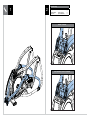
6
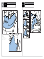
1 2
Red Hardware Bag
Description Qty
Socket Head Bolt
Flat Washer
(M10x1.5P-25L)
(Φ10.2xΦ20x2.0T)
4
4
ASCENT TRAINER
SUSPENSION ELLIPTICAL TRAINER

7
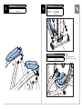
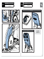
3 4
Pink Hardware Bag
Description Qty
Screw (M5x0.8Px16L) 2
Green Hardware Bag
Description Qty
Socket Head Bolt
Flat Washer
Hex Nut
(M10x1.5Px100L)
(Φ10.2xΦ20x2.0T)
(M10) Class 10
1
2
1
Yellow Hardware Bag
Description Qty
Screw (M5x0.8Px10L) 5
Note:
Use torque wrench and
tighten to (70 N-m - 90 N-m)

8
65
Red Hardware Bag
Description Qty
Socket Head Bolt
Flat Washer
(M10x1.5Px25L)
(Φ10.2xΦ20x2.0T)
4
4

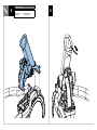
9
7
Blue / Black Hardware Bags
Description Qty
Screw
Spring Washer
Socket Head Bolt
Screw
Socket Head Bolt
Screw
(M5x0.8Px16L)
(Φ8.2xΦ15.4x2.0T)
(M8x1.25Px20L)
(M5x0.8Px16L)
(M8x1.25Px45L)
(M5x0.8Px12L)
2
8
8
4
2
4
8
ASCENT TRAINER
White Hardware Bag
Description Qty
Socket Head Bolt
Spring Washer
Screw (ALB only)
4
4
2
SUSPENSION ELLIPTICAL TRAINER
ASCENT LOWER BODY (ALB)

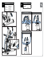
10
9
Pink Hardware Bag
Description Qty
Screw (M5x0.8Px16L) 1
Note:
Be careful not to
pinch any wires while
tightening screw.
10
Pink Hardware Bag
Description Qty
Screw (M5x0.8Px16L) 2

11
11
Pink Hardware Bag
Description Qty
Screw (M5x0.8Px16L) 2
12
Yellow Hardware Bag
Description Qty
Screw (M5x0.8Px16L) 5
5X, 7XE, 7XI
3X
ASSEMBLY
COMPLETE!

12
BEFORE YOU BEGIN
LOCATION OF THE UNIT
Place the equipment on a level and stable surface away from direct sunlight.
The intense UV light can cause discoloration on the plastics. Locate the
equipment in an area with cool temperatures and low humidity. Please
leave a free area behind the equipment that is at least 0.6 meters (24
inches). This area must be clear of any obstruction and provide the user
a clear exit path from the equipment. Do not place the equipment in
any area that will block any vent or air openings. The equipment should
not be located in a garage, covered patio, near water or outdoors.
LEVELING THE EQUIPMENT
The equipment should be level for optimum use. Once you have
placed the equipment where you intend to use it, raise or lower one
or both of the adjustable levelers located on the bottom of the frame.
Use 6mm hex key through the access hole (shown below).
A carpenter’s level is recommended.
NOTE: There are only two levelers on the equipment.
WARNING!
Our equipment is heavy, use care and additional help if necessary when
moving. Failure to follow these instructions could result in injury.
FREE AREA
0.6 m (2 Ft)
WORKOUT OPTIONS
LOWER BODY WORKOUT
To focus on a lower body workout, hold
the stationary handlebars only. This
will target your lower body muscles.
FULL BODY WORKOUT
For a full body workout, push
and pull continuously on the dual
action arms while pedaling.
POWER
If the equipment is powered by a power supply, the power must be plugged
into the power jack, which is located in the front of the equipment near the
stabilizer tube. Some equipment has a power switch, located next to the power
jack. Make sure it is in the ON position. Unplug cord when not in use.
MOUNTING THE ELLIPTICAL AND ASCENT TRAINER
1. Stand behind the equipment.
2. While holding both of the rear arm rests for support, place
your foot on the lowest foot pedal and push pedal down into
the lowest position before stepping onto foot pedal.
3. Wait until the equipment finds its resting place and then
place your other foot on the opposite pedal.
WARNING!
Never operate equipment if it has a damaged cord or plug, if it is not working properly, if it has been
damaged, or immersed in water. Contact Customer Tech Support for examination and repair.

13
PROPER USAGE
This equipment offers a variety of
foot positions. Moving your foot to
the forward most position of the foot
pad increases your step height, which
will create a feel similar to a step
machine. Placing your foot toward
the back of the foot pad decreases
your step height and creates more
of a gliding feel, similar to a smooth
walk or run. Always make sure your
entire foot is secured on the foot pad.
This equipment also allows you to pedal
both forward and backwards to offer a
variation to your workout and to focus
on other major leg muscle groups
such as your hamstrings and calves.
To determine proper workout position, stand on the pedal with
your foot on the center of the pedal. Keep your knees slightly
bent at all times. You should be able to pedal without locking
your knees or shifting your weight from side to side.
POWER INCLINE OPERATION
The Ascent Trainers offer powered incline to add variety to your workouts.
The incline can be adjusted using the buttons on the console.
If the stop button is pressed to pause the program, the incline motor will
remain at its current height. To return the incline to 0%, press GO and
change the incline to 0% before dismounting. If the STOP button is held
for 3 seconds to reset the console, the incline will also return to 0%.
USING THE HEART RATE FUNCTION
The heart rate function on this product is not a medical device. While heart rate grips
can provide a relative estimation of your actual heart rate, they should not be relied
on when accurate readings are necessary. Some people, including those in a cardiac
rehab program, may benefit from using an alternate heart rate monitoring system
like a chest or wrist strap. Various factors, including movement of the user, may affect
the accuracy of your heart rate reading. The heart rate reading is intended only as an
exercise aid in determining heart rate trends in general. Please consult your physician.
PULSE GRIPS
Place the palm of your hands directly on the grip pulse handlebars. Both hands must grip
the bars for your heart rate to register. It takes 5 consecutive heart beats (15-20 seconds)
for your heart rate to register. When gripping the pulse handlebars, do not grip tightly.
Holding the grips tightly may elevate your blood pressure. Keep a loose, cupping hold.
You may experience an erratic readout if consistently holding the grip pulse handlebars.
Make sure to clean the pulse sensors to ensure proper contact can be maintained.
WIRELESS HEART RATE RECEIVER
When used in conjunction with a wireless chest transmitter, your heart rate
can be transmitted wirelessly to the unit and displayed on the console.
Prior to wearing the wireless chest transmitter on your chest, moisten the two rubber
electrodes with water. Center the chest strap just below the breast or pectoral muscles,
directly over your sternum, with the logo facing out. NOTE: The chest strap must be tight and
properly placed to receive an accurate and consistent readout. If the chest strap is too loose,
or positioned improperly, you may receive an erratic or inconsistent heart rate readout.
WARNING!
Heart rate monitoring systems may be inaccurate. Over exercising may result in
serious injury or death. If you feel faint, stop exercising immediately.
Backside of chest strap
Apply moisture here

14
MAINTENANCE SCHEDULE
ACTION FREQUENCY
Unplug the unit. Clean entire machine using water and a mild soap or
other Matrix approved solution (cleaning agents should be alcohol and
ammonia free).
DAILY
Inspect the power cord. If the power cord is damaged, contact Customer
Tech Support.
DAILY
Make sure the power cord is not underneath the unit or in any other area
where it can become pinched or cut during storage or use.
DAILY
Check all connecting joint areas for tightness of bolt assemblies. QUARTERLY
Ensure that there is little, or no free play at all joint assemblies once bolts
have been tightened. Installation of washer kits may be required if free
play does not come out from tightening bolts.
QUARTERLY
Unplug the unit and remove plastic covers. Lubricate ball joint where the
Link Arm and Dual Action Handlebar join together. A grease gun, with
a needle tting adapter is required for this (Matrix recommends using
Superlube brand grease with PTFE {Teon} additive).
QUARTERLY
Unplug the unit and remove plastic covers. Lubricate Acme screw on
incline motor (Matrix recommends using Superlube brand grease with
PTFE {Teon} additive).
QUARTERLY
For 7xe consoles, enter service mode and select ‘test’. Select ‘touch
calibration’ and then select ‘start’. Follow the on-screen prompts and touch
the screen where indicated.
QUARTERLY
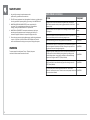
MAINTENANCE
1. Any and all part removal or replacement must be
performed by a qualied service technician.
2. DO NOT use any equipment that is damaged and or has worn or broken parts.
Use only replacement parts supplied by your country’s local MATRIX dealer.
3. MAINTAIN LABELS AND NAMEPLATES: Do not remove labels for
any reason. They contain important information. If unreadable or
missing, contact your MATRIX dealer for a replacement.
4. MAINTAIN ALL EQUIPMENT: Preventative maintenance is the key to
smooth operating equipment as well as keeping your liability to a
minimum. Equipment needs to be inspected at regular intervals.
5. Ensure that any person(s) making adjustments or performing maintenance
or repair of any kind is qualied to do so. MATRIX dealers will provide
service and maintenance training at our corporate facility upon request.
WARNING
To remove power from the Ascent Trainer / Elliptical, the power
cord must be disconnected from the wall outlet.

15
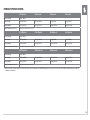
PRODUCT SPECIFICATIONS
A7xi Ascent A7xe Ascent A5x Ascent A3x Ascent
Max User Weight 182 kg / 400 lbs
Product Weight 202.7 kg / 445 lbs 202.7 kg / 445 lbs 201 kg / 442 lbs 201 kg / 442 lbs
Shipping Weight 216.5 kg / 476 lbs 216.5 kg / 476 lbs 214.6 kg / 472 lbs 214.6 kg / 472 lbs
Overall Dimensions (L x W x H)* 178 x 74.2 x 174 cm / 81” x 34” x 79”
E7xi Elliptical E7xe Elliptical E5x Elliptical E3x Elliptical
Max User Weight 182 kg / 400 lbs
Product Weight 182.7 kg / 402 lbs 182.7 kg / 402 lbs 181 kg / 398 lbs 181 kg / 398 lbs
Shipping Weight 195.5 kg / 430 lbs 195.5 kg / 430 lbs 193.5 kg / 425 lbs 193.5 kg / 425 lbs
Overall Dimensions (L x W x H)* 178 x 74.2 x 174 cm / 81” x 34” x 79”
ALB7xi Ascent ALB7xe Ascent ALB5x Ascent ALB3x Ascent
Max User Weight 182 kg / 400 lbs
Product Weight 197.2 kg / 435 lbs 196.5 kg / 434 lbs 195.9 kg / 432 lbs 194.4 kg / 429 lbs
Shipping Weight 220.6 kg / 487 lbs 219.6 kg / 485 lbs 219.2 kg / 484 lbs 217.3 kg / 479 lbs
Overall Dimensions (L x W x H)* 178 x 74.2 x 174 cm / 81” x 34” x 79”
* Ensure a minimum clearance width of 0.6 meters (24”) for access to and passage around MATRIX equipment. Please note, 0.91 meters (36”) is the ADA recommended clearance width for
individuals in wheelchairs.

Ascent / Ellipticals Frame
© 2015 Johnson Health Tech
Part # XXXXXXXXXX
Rev 1.0
-
 1
1
-
 2
2
-
 3
3
-
 4
4
-
 5
5
-
 6
6
-
 7
7
-
 8
8
-
 9
9
-
 10
10
-
 11
11
-
 12
12
-
 13
13
-
 14
14
-
 15
15
-
 16
16


Matrix A3x-04 Owner's manual
- Type
- Owner's manual
Ask a question and I''ll find the answer in the document
Finding information in a document is now easier with AI
Related papers
Other documents
-
AFG 18.0 AXT User manual
-
Vision Fitness S7100 Owner's manual
-
 Matrix Fitness PCTV User manual
-
 Pinnacle Systems 210100387 User manual
-
Horizon Fitness AT1501 User manual
-
-
-
Pulse 240 User manual
-
-
True fuse XL-1000 User manual

