Page is loading ...

INGERSOLL RAND COMPANY LTD
P.O. BOX 151
y
ONE ARO CENTER
y
BRYAN, OHIO 43506-0151
(800) 276-4658
y
FAX (800) 266-7016
© 2010 CCN 99711251
662605, 662606, 662608 & 662609
PUMP ASSEMBLY
READ THIS MANUAL CAREFULLY BEFORE INSTALLING,
OPERATING OR SERVICING THIS EQUIPMENT.
It is the responsibility of the employer to place this information in the hands of the operator. Keep for future reference.
6” AIR MOTOR
100:1 RATIO
0 - 10,000 PSI. RANGE
SERVICE KITS
Use only genuine ARO® replacement parts to assure com-
patible pressure rating and longest service life.
65130 packing kit.
61355 for air motor service only.
SPECIFICATIONS
Model Series . . . . . . . . . 662605, 662606, 662608 & 662609.
Type . . . . . . . . . . . . . . . . . Air Operated Grease Pump
Ratio . . . . . . . . . . . . . . . 100:1
Air Motor Diameter. . . . . . . . . . . . . . 6” (15.2 cm)
Stroke. . . . . . . . . . . . . . . . . . . . . . 4” (10.2 cm)
Air lnlet (female) . . . . . . . . . . . . . 1/2-14 N.P.T.F.
Material Outlet (female). . . . . . . 1/2 - 14 N.P.T.F.
Dimensional Data . . . . . . . . . . . . . . . . see chart
PERFORMANCE
Air Inlet Pressure Range . . . . .
0 - 100 p.s.i.g (0 - 6.9 bar)
Fluid Pressure Range . . . . . . . 0 - 10,000 p.s.i.g (0 - 690 bar)
Maximum Delivery/ Min . . . . 2.1 lbs (0.95 kg)
y
y
y
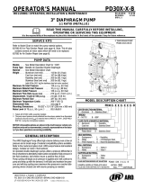
“B”
“A”
662605
662606
662608
662609
Figure 1
MODELS
“A” (mm)
662605, 662606
662608, 662609
39-5/8” (1006)
49-7/16” (1256)
25-7/16” (646)
35-1/4” (895)
120 lb.
400 lb. (55 gal.)
“B” (mm)
Drum Size
NOTE: Dimensions are shown in inches and (mm), supplied for reference
only and are typically rounded up to the nearest 1/16 inch.
OPERATING AND SAFETY PRECAUTIONS
WARNING
READ THE GENERAL INFORMATION MAN-
UAL INCLUDED FOR ADDITIONAL OPERATING AND
SAFETY PRECAUTIONS AND OTHER IMPORTANT IN-
FORMATION.
WARNING
EXCESSIVE INLET PRESSURE. Can cause
explosion resulting in severe injury or death. Do not
exceed maximum operating pressure of 10,000 p.s.i.g
(690 bar) at 100 p.s.i.g (6.9 bar) inlet air pressure. Do
not run pump without using a regulator to limit air
supply pressure to the pump.
WARNING
EXCESSIVE MATERIAL PRESSURE. Can cause
equipment failure resulting in severe injury or prop-
erty damage. Do not exceed the maximum material
pressure of any component in the system.
PUMP RATIO X
=
MAXIMUM PUMP
INLET PRESSURE TO PUMP MOTOR FLUID PRESSURE
Pump ratio is an expression of the relationship between the pump
motor area and the lower pump end area. EXAMPLE: When 100 p.s.i.g
(6.9 bar) inlet pressure is supplied to the motor of a 100:1 ratio pump it
will develop a maximum of 10,000 p.s.i.g (690 bar) uid pressure (at no
ow) - as the uid control is opened, the ow rate will increase as the
motor cycle rate increases to keep up with the demand.
NOTICE
Thermal expansion can occur when the uid in the ma-
terial lines is exposed to elevated temperatures. Example: Material lines
located in a non-insulated roof area can warm due to sunlight. Install a
pressure relief valve in the pumping system.
OPERATOR’S MANUAL 66260X
INCLUDING: OPERATION, INSTALLATION & MAINTENANCE
INCLUDE MANUAL: 6564X-X AIR MOTOR (97999-174), AIRLINE SAFETY INFORMATION (100400-76)
& S-633 GENERAL INFORMATION (PN 97999-624).
RELEASED: 8-26-09
REVISED: 3-17-10
(REV. G)
66260X MODEL OPERATOR’S MANUAL
6564X-X AIR MOTOR OPERATOR’S MANUAL
100400-76 AIRLINE SAFETY INFORMATION MANUAL
This is one of four documents which support the pump.
Replacement copies of these forms are available upon request.
IMPORTANT
S-633
GENERAL INFORMATION LUBRICATION PISTON PUMPS

Page 2 of 4 66260X
Item Description
(size in inches)
Qty Part No.
1 Tube
(662605 & 662606)
(1) 92625-1
(662608 & 662609)
(1) 92625-2
2 Rod
(662605 & 662606)
(1) 92629-1
(662608 & 662609)
(1) 92629-2
3 Adapter (1) 92621
4 Pin (1) 92624
5 BaIl Guide (1) 92623
6 BalI (1) Y16-211
7 Piston and CyIinder (1) 66714
8 Gasket (1) 92628
9 Tube (1) 92627
10 Primer Rod (1) 90131
11 Washer (1) 90136
12 Foot Valve Sleeve (1) 4170
13 Snap Ring (1) Y147-77
14 Cup (1) 90757
15 Body (1) 90756
16 Washer (1) F21-56
17 Foot Valve Seat (1) 93269-1
18 Washer (1) 90133
19 Washer (1) 92630
20 Elastic Stop Nut (1) 95977302
21 Primer Tube (1) 92626
PARTS LIST / LOWER PUMP END
INSTALLATION
Remove pump from packaging material and install and secure
pump to cover, bung or other mounting accessory as ordered.
See gure 2 for view of complete assembly.
Before connecting pump, first blow out material line
with air.
After the system is hooked up, pump a small amount
of material through the line. This material should be
discarded. (Do this to clear any foreign material out of
lines).
1.
2
.
OPERATING INSTRUCTIONS
Be sure material hose, lines and other components are
able to withstand pressure developed by pumps.
When a pump is installed and ready to operate: Connect air
supply to air motor inlet. Regulate air pressure from p.s.i.g
(2.07 bar) to 50 p.s.i.g (3.4 bar). Allow pump to cycle slowly
to prime with material and bleed all air from system
.
1.
MAINTENANCE
If the pump is to be inoperative for a lengthly period of time (a
few hours), disconnect air and relieve all pressure from system.
Periodically flush pump with a solvent that is compatible
with material being pumped.
Disassembly should be done on a clean work bench with
clean cloths to keep parts clean.
If replacement parts are necessary, consult drawings contain-
ing parts for identi cation.
Before reassembling, lubricate parts where required. When
assembling “0” rings or parts adjacent to “0” rings, care must
be exercised to prevent damage to “0” rings and “0” ring
groove surfaces.
Clean threads with
solvent and apply
Loctite 271 sealant
to threads.
See View “A”
1
2
3
4
5
6
7
8
9
10
11
12
16
18
19
20
21
15
17
13
14
View “A”
Figure 2
(1 & 9) 300 ft lbs (406.8 Nm) minimum.
TORQUE REQUIREMENTS

66260X Page 3 of 4

Page 4 of 4 66260X
PN 97999-75
TROUBLE SHOOTING
No material at outlet. (Pump continuously cycles).
Empty material supply. Disconnect the air, replenish the
material supply.
Foreign matter is holding foot valve seats open in lower
pump tube assembly. Remove lower pump tube assem-
bly and clean valve seats.
Pump operates sluggishly, tends to stick when air is
applied or control is opened.
Air motor is dirty or lacks lubrication. Clean air motor.
Insu cient air pressure or volume of air. Check air supply.
y
y
y
y
Air bypasses through exhaust port.
Foreign matter is holding air valve open or lacks lubrica-
tion. Consult factory for nearest Service Center.
Motor stalls.
Foreign matter in pump, hose, control valve or spray tip
obstructing material flow. Check material supply hose
and control valve or tip.
Air not getting to pump. Check air supply.
y
y
y
/