200-0255 SEPT 2013
Users’ Installation
Operation and
Maintenance Manual
7116 Beatty Dr
Mission, BC V2V 6B4
Canada
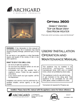
CHALET 1600
CHALET 1600
Wood Burning
Stove
PRIOR TO FIRST FIRE: Remove all labels from glass. Clean fingerprints from plated
surfaces with a glass cleanser and soft cloth to prevent permanent staining.
CHILDREN AND ADULTS SHOULD BE ALERTED TO THE HAZARDS OF HIGH SURFACE
TEMPERATURES, ESPECIALLY THE STOVE GLASS, AND SHOULD STAY AWAY TO AVOID BURNS
OR CLOTHING IGNITION. THIS UNIT CONTAINS SMALL PARTS DURING ASSEMBLY THAT SHOULD
BE KEPT AWAY FROM CHILDREN DUE TO CHOKING HAZARD WHICH COULD RESULT IN PERSONAL
INJURY OR DEATH.
Installer: Please complete the details on the back cover
and leave this manual with the homeowner.
Homeowner: Save These Instructions for future reference.

IMPORTANT SAFETY NOTES
1. When installing your stove, particular attention should be paid to fire protection. If this room heater is not
properly installed, a house fire may result. To reduce the risk of fire, follow the installation instructions. Con-
tact local building, fire officials or authority having jurisdiction about restrictions, installation inspection and
permit requirements in your area.
2. CAUTION: Never use gasoline, gasoline-type lantern fuel, kerosene, charcoal lighter fluid, or similar liquids
to start or “freshen up” a fire in this heater. Keep all such liquids well away from the heater while it is in use.
3. DO NOT BURN GARBAGE OR FLAMMABLE FLUIDS SUCH AS GASOLINE, NAPHTHA OR ENGINE OIL.
Do not burn treated wood, or wood with salt (driftwood, etc.). Burning materials other than wood (including
charcoal) under adverse conditions may generate carbon monoxide in the home, resulting in illness or possi-
ble death.
4. Do not store any fuel closer than 2 feet from your unit. Do not place wood, paper, furniture, drapes or other
combustibles near the appliance.
5. During operation, if any part of the stove starts to glow, the stove is in an over-fired condition. Close the air
control completely by pushing it in until the glowing has stopped. OVERFIRING VOIDS YOUR WARRANTY!
6. RISK OF FIRE! Do not operate with stove door or ash removal system door open.
7. Your woodstove should burn dry, standard firewood only. The use of cut lumber, plywood, “mill ends”, etc. is
not recommended as this fuel can easily overheat your woodstove. Salt water driftwood and chemically
treated fire logs also must not be burned in your woodstove.
8. WARNING! Never draw outside combustion air from a wall, floor or ceiling cavity or from any
enclosed space such as an attic or garage, carport or under a mobile home.
9. Check your chimney system thoroughly when installing into an existing metal or masonry chimney. Seek
professional advice if in doubt about its condition.
10. Comply with all minimum clearances to combustibles as shown in this manual for this appliance.
11. Build fire on brick firebox floor. Do not use grates, andirons or other methods to support fuel.
12. HOT WHILE IN OPERATION! Keep children, pets, clothing and furniture away. Contact can cause skin
burns.
13. Do not operate without fully assembling all components. Burning your stove without the legs attached (if
supplied with unit) will void your warranty, and could present a serious safety hazard.
14. All fuel burning appliances consume oxygen during operation. It is important that you supply a source of
fresh air to your unit while burning. A slightly opened window is sufficient for this purpose. If you also have a
fireplace in your home, a downdraft may be created causing a draft down your chimney. Provide adequate
ventilation.
15. The controls of your unit or the air supply passages should not be altered to increase firing for any reason.
16. If you burn the unit too slowly or at too low a setting your unit will not be operating as efficiently as it can. An
easy rule of thumb says that if your glass is clean, then your flue is clean and your exhaust is clean. Burn the
stove hot enough to keep your glass clean and you won't need to clean your flue as often.
17. Burning wet or green, unseasoned wood, could cause excessive creosote accumulation in the flue pipe and
chimney. This could result in a chimney fire. Store wood in a dry location.
18. Do not permit creosote or soot build-up in the chimney system. Check and clean chimney at regular inter-
vals. Failure to do so can result in a serious chimney fire.
19. Cool ashes should be disposed of carefully, using a metal container.
20. Do not connect to any air distribution duct or system.
21. Do not connect this unit to a chimney flue already serving another appliance.
22. This appliance must be connected to a vent and terminate to the outside of the building envelope. Never
vent to another room or inside a building.
23. Do not operate if the gasket on the door or ash plug is missing or damaged.
24. Do not operate with broken glass.
25. For further information refer to NFPA 211 (USA) or CAN/CSA-B365 (Canada).

Chalet 1600 3
Congratulations on choosing a state-of-the-art Archgard Hearth Product!
The hand crafted Chalet 1600 has been designed to provide you with comfort, security and
economy for many years of trouble-free enjoyment.
It has been our experience that the overall enjoyment of your new appliance will be greatly
enhanced by becoming familiar with its installation, operation and maintenance. Prior to
installation, we ask that you take a few moments to read this manual.
We wish you and your family many years of enjoyment in the warmth and comfort of this
hearth appliance.
Thank you for choosing Archgard Industries!
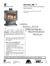
CHALET 1600
Legs & Bottom Shield
Ash Drawer & Lid
Ash Drawer & Lid
Pedestal
Optional
Combustion
Air

Chalet 1600 4
Important Safety Notes
5
Rating Plate Label
7
Clearances
8
Dimensions - Pedestal Unit
9
Dimensions - Leg Unit
10
Specifications
11
Pedestal Assembly Instructions
12
Leg Assembly Instructions
13
Door Assembly Instructions
14
INSTALLATION METHODS
Door Installation 15
Air Tube Installation 16
Mobile Home Installation - Listed Components 17
Blower / Fan Installation 18
Residential Installation 19
Mobile Home Installation 21
Chase Enclosure / Masonry Chimney 22
Recommended Minimum Chimney Heights 24
Vent Specifications / First Fire 25
MAINTENANCE
Troubleshooting 26
Creosote & Chimney Fires 28
In Case of a Chimney Fire / Chimney Maintenance / Wood 29
Door Gasket / Latch Adjustment / Glass 31
Glass Maintenance 32
Ash Disposal 33
ACCESSORY / PARTS REPLACEMENT
Exploded view of Chalet 1600 - Parts 34
Accessory & Replacement Parts List 35
Archgard Warranty 36
Warranty Registration Card 37
Notes 40
Installation Information 41
TABLE OF CONTENTS

Chalet 1600 5
IMPORTANT SAFETY NOTES
1. When installing your stove, particular attention should be paid to fire protection. If this room heater is not
properly installed, a house fire may result. To reduce the risk of fire, follow the installation instructions. Con-
tact local building, fire officials or authority having jurisdiction about restrictions, installation inspection and
permit requirements in your area.
2. CAUTION: Never use gasoline, gasoline-type lantern fuel, kerosene, charcoal lighter fluid, or similar
liquids to start or “freshen up” a fire in this heater. Keep all such liquids well away from the heater
while it is in use.
3. DO NOT BURN GARBAGE OR FLAMMABLE FLUIDS SUCH AS GASOLINE, NAPHTHA OR ENGINE OIL.
Do not burn treated wood, or wood with salt (driftwood, etc.). Burning materials other than wood (including
charcoal) under adverse conditions may generate carbon monoxide in the home, resulting in illness or possi-
ble death.
4. Do not store any fuel closer than 2 feet from your unit. Do not place wood, paper, furniture, drapes or other
combustibles near the appliance.
5. During operation, if any part of the stove starts to glow, the stove is in an over-fired condition. Close the air
control completely by pushing it in until the glowing has stopped. OVERFIRING VOIDS YOUR WARRANTY!
6. RISK OF FIRE! Do not operate with stove door or ash removal system door open.
7. Your woodstove should burn dry, standard firewood only. The use of cut lumber, plywood, “mill ends”, etc. is
not recommended as this fuel can easily overheat your woodstove. Salt water driftwood and chemically
treated fire logs also must not be burned in your woodstove.
8. WARNING! Never draw outside combustion air from a wall, floor or ceiling cavity or from any
enclosed space such as an attic or garage, carport or under a mobile home.
9. Check your chimney system thoroughly when installing into an existing metal or masonry chimney. Seek
professional advice if in doubt about its condition.
10. Comply with all minimum clearances to combustibles as shown in this manual for this appliance.
11. Build fire on brick firebox floor. Do not use grates, andirons or other methods to support fuel.
12. HOT WHILE IN OPERATION! Keep children, pets, clothing and furniture away. Contact can cause skin
burns.
13. Do not operate without fully assembling all components. Burning your stove without the legs attached (if
supplied with unit) will void your warranty, and could present a serious safety hazard.
14. All fuel burning appliances consume oxygen during operation. It is important that you supply a source of
fresh air to your unit while burning. A slightly opened window is sufficient for this purpose. If you also have a
fireplace in your home, a downdraft may be created causing a draft down your chimney. Provide adequate
ventilation.
15. The controls of your unit or the air supply passages should not be altered to increase firing for any reason.
16. If you burn the unit too slowly or at too low a setting your unit will not be operating as efficiently as it can. An
easy rule of thumb says that if your glass is clean, then your flue is clean and your exhaust is clean. Burn the
stove hot enough to keep your glass clean and you won't need to clean your flue as often.
17. Burning wet or green, unseasoned wood, could cause excessive creosote accumulation in the flue pipe and
chimney. This could result in a chimney fire. Store wood in a dry location.
18. Do not permit creosote or soot build-up in the chimney system. Check and clean chimney at regular inter-
vals. Failure to do so can result in a serious chimney fire.
19. Cool ashes should be disposed of carefully, using a metal container.
20. Do not connect to any air distribution duct or system.
21. Do not connect this unit to a chimney flue already serving another appliance.
22. This appliance must be connected to a vent and terminate to the outside of the building envelope. Never
vent to another room or inside a building.
23. Do not operate if the gasket on the door or ash plug is missing or damaged.
24. Do not operate with broken glass.
25. For further information refer to NFPA 211 (USA) or CAN/CSA-B365 (Canada).

Chalet 1600 6
SAFETY NOTE: If this woodstove is not properly installed, a house fire may result. For
your safety, follow the installation instructions, contact local building, fire officials, or au-
thority having jurisdiction about restrictions and installation inspection requirements in
your area.
The authority having jurisdiction should be consulted before installation to determine
the need to obtain a permit.
WHEN LOCATING YOUR STOVE: Consider safety, convenience, traffic flow, and the
fact that the stove will need a chimney and chimney connector. It is a good idea to plan
your installation on paper, using exact measurements for clearances and floor protec-
tion, before actually beginning the installation.
These installation instructions describe the installation and operation of the CHALET
1600 woodstove. This stove meets the U.S. Environmental Protection Agency’s 1990
particulate emission standards. The Chalet 1600 is listed by Omni Test Laboratories
Ltd. to UL Safety Standard 1482, ULC S627, and (UM) 84-HUD. The Chalet 1600 is
approved for mobile home installations when not installed in a sleeping room and when
an outside combustion air inlet is provided. The structural integrity of the mobile home
floor, ceiling, and walls must be maintained. The stove must be properly grounded to
the frame of the mobile home and use only listed double-wall connector pipe. The Mo-
bile Home Outside Air Kit must be installed in a mobile home installation. Measures
must be taken to avoid blockage of outside air ducting coupled to the outside air
kit when attached to the stove.
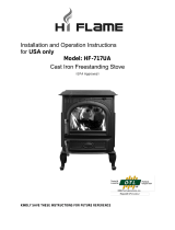
SAFETY LABEL
A copy of the label that accompanies each Archgard Chalet 1600, is printed on the next
page for your convenience.
NOTE: Archgard units are constantly being improved. If there is a conflict between the
label on the unit and the one printed here, the label on the unit is the correct one. The
safety label is located on the back panel of the stove.
YOUNG CHILDREN SHOULD BE CAREFULLY SUPERVISED WHEN THEY ARE IN
THE SAME ROOM AS THE APPLIANCE.

Chalet 1600 7
DO NOT REMOVE THIS LABEL
FLOOR PROTECTION
Any combustible flooring or floor covering beneath the appli-
ance and / or within the area extending horizontally beyond
the appliance on any side equipped with a door, and beyond
the appliance on the other sides and rear, shall be protected
by a continuous, durable, noncombustible pad that will pro-
vide ember protection.
Refer to Canadian CSA B365 and USA NFPA 211 Installation
Codes for details.
For use with solid fuel only. Use of other fuels may damage the heater and create a hazardous condition. Do not obstruct combustion air opening or
space between the heater. Operate only with firebricks in place. Risk of smoke and flame spillage. Operate only with doors fully closed. Open front
door to feed fire only. Do not use grate or elevated fire, build wood fire directly on hearth. DO NOT OVERFIRE - IF HEATER OR CHIMNEY
CONNECTOR GLOWS YOU ARE OVER-FIRING. Inspect and clean chimney connector frequently, under certain conditions of use creosote
build-up may occur rapidly. Keep furnishings and other combustibles away from heater. Replace glass only with ceramic glass. Combustible floor may
be protected by non-combustible material extending beneath the heater and to the front and sides as indicated or to the nearest permitted combustible
material. Optional fan kit Part # FK-1800 electrical rating 115 Volts 60 Hz 2 Amps. DANGER: risk of electrical shock, disconnect power before ser-
vicing unit. Components required for Mobile Home Installation: Outside Air Kit and double wall connector with listed chimney system.
Manufactured by: ARCHGARD INDUSTRIES LTD.
MISSION, BC ~ CANADA
Made in Canada
UNITED STATES ENVIROMENTAL PROTECTION AGENCY
CERTIFIED TO COMPLY WITH JULY 1990 PARTICULATE EMMISION STANDARDS
BACKWALL
SIDEWALL
ADJACENT WALL
8”
FRONT
FRONT
SIDEWALL
DATE OF MANUFACTUR:
2007 2008 2009 JAN FEB MAR APR MAY JUN JUL AUG SEP OCT NOV
DEC
SIDE
8” 8”
SIDE
6”
SIDE
6”
SIDE
PREVENT HOUSE FIRES:
INSTALL ONLY IN ACCORDANCE WITH THE MANUFACTURER’S INSTALLATION AND OPERATING INSTRUCTIONS. CONTACT LOCAL BUILDINGOR FIRE OFFI-
CIALS ABOUT RESTRICTIONS AND INSTALLATION INSPECTION IN YOUR AREA. USE 6 in (152 mm) DIAMETER MINIMUM 24MSG BLACK OR MSG BLUED
STEEL CONNECTOR WITH LISTED UL103 HT (IN USA) OR ULC S629 (IN CANADA) FACTORY BUILT CHIMNY SUITIBLE FOR USE WITH SOLID FUELS OR MA-
SONRY CHIMNEY. SEE LOCAL BUILDING CODE OR MANUFACTURER’S INSTRUCTIONS FOR PRECAUTIONS REQUIRED FOR PASSING A CHIMNEY
THROUGH A COMBUSTIBLE WALL OR CEILING, DO NOT PASS CHIMNEY CONNECTOR THROUGH COMBUSTIBLE CEILING. DO NOT CONNECT THIS UNIT TO
A CHIMNEY SERVING ANOTHER APPLIANCE.
LISTED SPACE HEATER, SOLID FUEL TYPE.
ALSO SUITABLE FOR MOBILE HOME INSTALLATION.
SERIAL NUMBER / NUMÉRO DE SÉRIE:
MODEL: CHALET 1600 FREE STANDING STOVE
TESTED TO: UL 1482-96 / ULC S627-00
INSTALLATION USING LISTED DOUBLE WALL CONNECTOR OUT THE BACK WALL
SIDEWALL C-279 mm/ 11” B-584mm / 23”
BACKWALL F- 356 mm/ 14” E- 508mm / 20”
STOVE TO CEILING : A- 1410 mm/ 55.5 “
PIPE TO CEILING CLEARANCE : (NFPA—NOT TESTED) D- 457mm/ 18”
SEE MANUAL FOR ADDITIONAL CLEARANCES
INSTALLATION USING SINGLE WALL CONNECTOR OUT THE BACK WALL
SIDEWALL C –356mm/14” B–660mm/26”
BACKWALL F- 356mm/14” E -508mm/ 20”
STOVE TO CEILING A - 1410mm/55.5”
PIPE TO CEILING CLEARANCE (NFPA– NOT TESTED) D - 457mm / 18”
INSTALLATION USING LISTED DOUBLE WALL CONNECTOR - RESIDENTIAL & MOBILE HOME
SIDEWALL A - 279mm/ 11” D –584mm/ 23”
BACKWALL B - 203mm/ 8” E -356mm/ 14”
CORNER C - 203mm/ 8” F –457mm/ 18”
RESIDENTIAL INSTALLATION USING SINGLE WALL CONNECTOR
SIDEWALL A - 356mm/14” D -660mm/26”
BACKWALL B - 279mm/11” E -432mm/ 17”
CORNER C - 229mm/9” F - 483mm/ 19”
MEASURE FROM HEATER FLUE CENTRE LINE
MINIMUM CLEARANCES TO COMBUSTIBLE MATERIALS
Canadian Installations USA Installations
18”
16”
6”

Chalet 1600 8
RESIDENTIAL INSTALLATION USING SINGLE
WALL CONNECTOR
SIDEWALL A - 356 mm / 14”
D - 660 mm / 26”
BACKWALL B - 279 mm / 11”
E - 432 mm / 17”
CORNER C - 229 mm / 9”
F - 483 mm / 19”
INSTALLATION USING LISTED DOUBLE WALL CONNECTOR
MOBILE HOME, RESIDENTIAL CLOSE CLEARANCE
SIDEWALL A - 279 mm / 11” D - 584 mm / 23”
BACKWALL B - 203 mm / 8” E - 356 mm / 14”
CORNER C - 203 mm / 8” F - 457 mm / 18”
INSTALLATION USING LISTED DOUBLE WALL CONNECTOR - ALCOVE
SIDEWALL G - 330 mm / 13” I - 635 mm / 25”
BACKWALL H - 229 mm / 9” J - 381 mm / 15”
MAXIMUM ALCOVE DEPTH L - 915 mm / 36”
MINIMUM ALCOVE CEILING HEIGHT : 2108 mm / 83”
Minimum clearance from stove top to ceiling: 1388 mm / 54.625”
The floor pad (ember pad) must be of non-combustible material and must extend 16" in front of the
door opening and 6" to the sides and rear of the unit. In Canada, the floor pad (ember pad) must be
of non-combustible material and must extend 18" (450mm) in front of the door opening and
8" (200mm) to the sides and rear of the unit.
If the listed stove clearance is less than the required floor pad , use the stove listing. Contact your
local Authority Having Jurisdiction and/or the CSA B365 in Canada or NFPA 211 in USA for more
details.
Clearances may only be reduced by means approved by the regulatory authority.
K
FLOOR PAD US K - 1625 mm / 64” M - 1600 mm / 63”
CANADA K - 1676 mm / 66” M - 1651 mm / 65”
M

Chalet 1600 9
DIMENSIONS - PEDESTAL UNIT
11 3/8” (289mm)
29 1/8” (740 mm)
30 3/8 “ (772 mm)
24 in.
11 5/8 in
27 3/8 in
28 5/8 in
6 5/16 in
11 7/8 in
23 3/4 in
21 in
20 3/8 in
22 3/4 in

Chalet 1600 10
DIMENSIONS - LEG UNIT DIMENSIONS - LEG UNIT
NOTE: Height measurement is without the leveling bolts installed
31 3/8 “ (797 mm)
30 1/8” (765 mm)
12 3/8” (314 mm)
23 3/4 in
11 7/8 in
6 5/16 in.
21 in
29 5/8 in
28 3/8 in
12 5/8 in
22 3/8 in
17 3/8 in
22 3/4 in

Chalet 1600 11
SPECIFICATIONS
MODEL CHALET 1600 FREESTANDING
LEG PEDESTAL
WIDTH x DEPTH 24 in. W X 22 3/4 in. D
HEIGHT 29 5/8 in || 28 5/8 in
HEIGHT OF BODY 15 1/8 in.
E.P.A. EMISSIONS 2.88 g/hr.
E.P.A. OUTPUT RATING 63%
APPROXIMATE HEATING AREA 800 — 1500 Square Feet
DURATION ON LOW FIRE 6 - 12 hours
STOVE WEIGHT
WITH PACKAGING
300 lbs

Chalet 1600 12
1. For easier assembly, tip the stove body on
its back (preferably onto a soft surface to
prevent scratching).
2. Slide the pedestal up against the bottom of
the stove. You will be aligning the 4 holes in
the corners of the pedestal with the corre-
sponding holes in the base of the stove.
3. Use a centering device, such as a center
punch and lift one corner of the pedestal and
push the centering device loosely through
the hole in the pedestal corner and into the
“Tee” nut in the base of the stove (If you
haven’t removed the bricks, be very careful
not to loosen them - two people would be
helpful for this job)
PEDESTAL ASSEMBLY
NOTE: The Chalet 1600 stove body comes
strapped to a pallet with the bricks, secondary air
tubes and baffle plates already installed.
Take care when laying the stove on its back to in-
stall the Pedestal or Leg and Bottom Shield / Skirt
Assembly. You may want to remove the bricks be-
fore laying the stove down.
The Pedestal Assembly and the Bottom Shield /
Skirt Assembly (skirt and ash drawer) come pack-
aged in separate boxes. The legs are packaged
separately as is the cast door.
PEDESTAL, BOTTOM SHIELD / SKIRT LEG - ASSEMBLY INSTRUCTIONS
4. Now swing the pedestal up so that the opposite
holes align and install and tighten the supplied
5/16” x ½” bolt and 2 washers per bolt with a ½”
wrench.
Remove the centering device and install the
remainder of the supplied 5/16” x ½” bolts and
washers and tighten them with a ½” wrench.
5. Lift the unit upright (two people would be help-
ful here also)
6. Slide in the ash drawer
7. Reinstall the bricks, if removed, and check the
positioning of the secondary air tubes and baf-
fle plates.
8. Correct positioning if necessary.
Unpack the stove and remove all the parts packed inside. Inspect all the parts and stove body for
shipping damage. Contact your dealer if any irregularities are noticed.

Chalet 1600 13
LEG ASSEMBLY
This applies to all painted and plated cast legs
1. Thread the 1/4” x 1” leveling bolts into the bottom of the
legs
2. Slip the 5/16” x 3/4” bolts through the very bottom of the
Bottom Shield / Skirt and install the supplied washer and
nut .
3. Slide each leg under the washer and tighten the nuts. Do
not over-tighten.
NOTE: Back leg sits flush with the back and side corner while
the front leg backs up against the front stop.
BOTTOM SHIELD / SKIRT ASSEMBLY
1. For easier assembly, tip the stove body on its back (preferably onto a soft surface to prevent scratch-
ing).
2. Slide the Bottom Shield / Skirt Assembly up against the bottom of the stove. You will be aligning the 4
holes in the corners of the Bottom Shield / Skirt Assembly with the corresponding holes in the base of
the stove.
3. Use a centering device, such as a center punch and lift one corner of the Bottom Shield / Skirt Assem-
bly and push the centering device loosely through the hole in the Bottom Shield / Skirt Assembly corner
and into the “Tee” nut in the base of the stove (If you haven’t removed the bricks, be very careful not to
loosen them - two people would be helpful for this job)
4. Now swing the Bottom Shield / Skirt Assembly up so that the opposite holes align and install and
tighten the supplied 5/16” x ½” bolt and 2 washers per bolt with a ½” wrench. Remove the centering
device and install the remainder of the supplied 5/16” x ½” bolts and washers and tighten them with a
½” wrench.
5. Lift the unit upright and place it into position on the floor (two people would be helpful here also). CAU-
TION! DO NOT TILT THE UNIT ON THE CAST IRON LEGS.
6. Slide in the ash drawer.
7. Reinstall the bricks, if removed, and check the positioning of the secondary air tubes and baffle plates.
Correct positioning if necessary.
8. Level the stove by adjusting the leveling bolts in the bottom of each leg.
5 / 16” x 3/4”
bolts &
washers
& nuts
Front leg
stop

Chalet 1600 14
The door comes assembled with the glass and gasket.
1. Run the threaded end of the handle
through the hole in the cast door.
2. Insert the clevis pin into the roller and
washer.
3. Insert the end of the clevis pin assembly
into the hole in the end of the handle
4. Close the door and see how the door
closes. If it is too tight, turn the handle
clockwise to loosen it. If it is too loose,
turn the handle counter clockwise to
bring the door closer to the stove body.
5. To verify that the doors are well sealed,
insert a piece of paper between the
door and the stove body. You shouldn’t
be able to pull the paper out. Tighten it
to the point where the paper is starting
to tear when you are pulling it out.
6. Insert the cotter pin into the end of the
clevis pin to keep the assembly from
coming apart.
7. Attach spring handle by rotating the
spring counter clockwise onto the rod.
Ensure that the spring screws onto the
rod at least ½”.
9. Cover the holes with the two decorative
plug buttons
Clevis Pin
Cotter Pin
Roller
Washer
Cotter pin goes
through clevis pin
as shown here:
CAUTION: THIS UNIT CONTAINS SMALL PARTS DURING ASSEMBLY THAT SHOULD BE KEPT AWAY
FROM CHILDREN DUE TO CHOKING HAZARD WHICH COULD RESULT IN PERSONAL INJURY OR DEATH.

Chalet 1600 15
BRICK INSTALLATION
The firebox of your Archgard stove is lined with high quality firebrick, which has exceptional insulating
properties. There is no need to use a grate; simply build the fire on the firebox floor of your stove. Do
not operate this stove without the firebrick.
The Firebrick is also intended to extend the life of your stove and radiate heat more evenly. Install the
bricks as in the photos and then cap them with the supplied channel capping material. All the bricks
are numbered and must be installed in the correct positions listed below. The parts listing on pg. 34 will
have the listing of the bricks.
CAUTION: THIS UNIT CONTAINS SMALL PARTS DURING ASSEMBLY THAT SHOULD BE KEPT AWAY FROM CHILDREN
DUE TO CHOKING HAZARD WHICH COULD RESULT IN PERSONAL INJURY OR DEATH.
Fire Brick Positions
Brick 1 = 311-1000
Brick 2 = 780-1110
Brick 3 = 780-1111
Brick 4 = 780-1112
1
2
3
4

Chalet 1600 16
The Air Tubes in the Archgard Chalet 1600 come already assembled with the baffle plates installed. If for
some reason they need to be removed or installed, the following guidelines must be adhered to. (The
stove must be cool)
1) Open the Archgard Freestanding Chalet 1600 door.
2) NOTE: The holes in the two back tubes are larger than the holes in the front tube. The left hand
side of the tubes have little “notches” or “relief's” cut into them that mate with the left hand
side of the stove that align the air hole for proper combustion.
3) The 2 ceramic baffles are fragile and must be installed as shown below. They are installed prior to put-
ting in the last tube in the front position.
4) Slide the 1’st rear tube into the right hand side hole, as far as possible and then bring it back into the
hole on the left hand side lining up the “relief or notch” cut into the tube on that side until it locks into
position. If the tube will not slide in easily, simply use a pair of vise grips or pliers and tap it into place
with a hammer. Then insert the cotter pin from the top through the hole.
4) Before installing the final air tube, slide the a lightweight baffle plate over the air tubes (leaving the
step joint in the middle) from the front and then push it to the back and over to side of the stove as far
as it can go. Do the same with the other lightweight baffle plate ensuring that the step in the middle will
overlap the previous lightweight baffle plate.
5) When both lightweight baffle plate are in, install the third secondary air tube.
Handle the ceramic baffle plates with care as they are fragile.
AIR TUBE INSTALLATION
1
2
3
4
Notches
Cotter Pins
Baffles shown in proper position.

Chalet 1600 17
LISTED COMPONENTS FOR MOBILE HOME INSTALLATION
OPTIONAL OUTSIDE AIR ADAPTOR
The adaptor is required if the Chalet 1600 is to be installed into a Mobile Home or location requiring out-
side combustion air.
Attach with supplied self tapping screw and
reinstall fan (if used). (Photo 3)
Attach 4” Collar supplied and bend taps to
secure against the adapter. Combustion air
duct (not included) from outside can now be
attached to the 4" round collar. (Photo 4)
Mobile home installation requires the use
of outside air. When outside air is to be
used, the Mobile Home Combustion Air
Adapter must be installed through the rear
of the stove base. (Photo 1)
Remove blower kit (if installed) Slide the
adapter into the “combustion air” slots in the
photo and slide it into the bottom of the unit.
(Photo 2)
3
1
2
Outside air can ONLY be brought into the unit using the Mobile Home combustion air adapter .
INSTALLATION
After installing the “Mobile Home Combustion Air adapter” to the appliance continue to layout the ducting.
Then cut or drill the hole in the wall and install the non-combustible ducting and insulation (if required). Cap the
system with either a rodent/pest screen hood or a ¼” mesh. Make sure the inlet is kept clear at all times to
allow air flow.

Chalet 1600 18
1. Remove the fan assembly from the box and inspect
for any damage to the assembly. If damage is no-
ticed call your dealer, distributor or courier company
and have components replaced before installing kit.
2. Locate the 2 holes in the bottom back of the heat shield
of the stove (shown in the photo).
3. Locate the 2 holes it the back top of the fan (with the
louver facing back)
4. With the two #8 self tapping screws at the ready, slide
the outlet end of the fan up into the rear heat shield lining up the 2 holes with each other.
5. After aligning holes, secure the fan to the rear heat shield using the two screws provided.
CAUTION: The connection cord should not be in contact with any hot surfaces. Do not route
cord under or in front of unit.
BLOWER / FAN INSTALLATION
WARNING: Electrical Grounding Instructions
This appliance is equipped with a three-pronged (grounding) plug for your protection against
shock hazard and should be plugged directly into a properly grounded three-prong receptacle.
Do not cut or remove the grounding prong from this plug.
FAN OPERATION
The Chalet 1600 is certified for operation with or
without the optional fan and may be installed at any
time by attachment at the back of the stove and
plugging in the 3-prong power cord.
Electrical Rating = 115V AC / 1.0 amps
Fan Output Rating = 150 c.f.m.
PART # FK-1800 FS
CAUTION
Label all wires prior to
disconnection when
servicing controls. Wir-
ing errors can cause im-
proper and dangerous
operation
FAN WIRING DIAGRAM
The Chalet 1600 fan kit comes complete with a temperature
activated fan and solid stat speed control. The heat sensor is
factory set to close the circuit to the fan speed control at 110
0
F (43
0
C) and will turn off the fan when the temperature falls
below 80
0
F (27
0
C).
The speed can be adjusted up/down and off with the knob on
the side of the fan housing

Chalet 1600 19
RESIDENTIAL INSTALLATION
CAUTION: At no time can unlabelled parts, or substitute parts made for another chimney system
be used. Install as per chimney manufacturer's installation instructions. Clearances may only be
reduced by means approved by the regulatory authority.
1. Please read this entire manual before you install and use your new Chalet 1600 woodstove. Failure
to follow instructions may result in property damage, bodily injury or even death. Be aware that local
Codes and Regulations may override some items in this manual. Check with your local Authority
Having Jurisdiction.
2. Select a location for your Archgard Chalet 1600 Stove. Double check the clearances on the label and
set the stove in place.
3. For a vertical installation, suspend a plumb bob from the ceiling over the exact center of your stove
flue collar or use a laser centering device and mark the ceiling to indicate the center of the chimney.
4. Check that the intended location does not interfere with trusses, joists or rafters before proceeding
further.
5. Cut a hole in the ceiling and roof to suit the chimney system and do any necessary framing as
required by the chimney manufacturer. Maintain the integrity of the vapor barrier. NOTE: Interior
chimneys shall be enclosed where they extend through closets, storage areas, occupied spaces, or
anyplace where the surface of the chimney could be contacted by persons or combustible materials.
6. Install required supports, fire stops, radiation shields, etc. Assemble chimney sections so that the
finished length is cradled in the support and protruding through the roof, install the flashing and
storm collar (in some cases you may have to install the flashing before the section of chimney goes
through the roof) . Attach rain cap. Depending on how much exposed chimney you have, you may
need to install roof braces.
Install chimney according to chimney manufacturer’s instructions. The performance of your
woodstove is largely dependant on the chimney system. Too short a chimney can cause difficult
start-ups, dirty glass, smoking problems when the door is open, and even reduced heat output.
Too tall a chimney can cause excessive draft which can result in very short burn times and
excessive heat output and possible overheating of the stove.
CAUTION: The chimney should be the same size as the 6" flue outlet on the stove. The Chalet
1600 woodstove must be connected to a listed UL 103 HT chimney in the USA or a listed ULC
S629 chimney in Canada or a code approved masonry chimney with a flue liner.
7. The floor pad (ember pad) must be of non-combustible material and must extend 16" in front of the
door opening and 6" to the sides and rear of the unit.
Note: In Canada, the floor pad (ember pad) must be of non-combustible material and must extend
18" (450mm) in front of the door opening and 8" (200mm) to the sides and rear of the unit. See your
local inspector or the CSA B365 in Canada or NFPA 211 in USA
8. If you are installing the mobile home combustion air adapter, position the stove on the floor/hearth
pad (ember pad) and mark the location of the hole in the wall, drill or cut the hole and install the
ducting and hood, with rodent screen and insulate if necessary.
9. When the stove is positioned with the flue collar centered under the chimney, hook up the connector
pipe and fasten it to the flue collar which has provisions for 3 screws and to the chimney as per
manufacturer’s instructions.

Chalet 1600 20
RESIDENTIAL INSTALLATION (cont’d)
11) In seismically active areas, Archgard recommends that your unit be secured to the floor by using
¼” lag bolts in the bolt down holes on the pedestal or legs (the same ones used for Mobile Home
installations).
12) For residential installations using 6" "C" Vent (single wall), the chimney connector must be at least
24 gauge steel. Do not use galvanized pipe. For Mobile Home installation, use only listed air
insulated double wall connector.
13) Do not connect this unit to a chimney serving another
appliance.
14) A chimney connector cannot pass through an attic or roof
space, closet or similar concealed space, or a floor, ceiling,
wall or partition of combustible construction. In Canada, if
passage through a wall, or partition of combustible
construction is desired, the installation shall conform to CAN/
CSA-B365, Installation Code for Solid-Fuel-Burning
Appliances and Equipment. In the U.S.A. install according to
NFPA 211.
Do not connect your Archgard Woodstove to an air distribution
duct.
Check with chimney manufacturer’s installation instructions for
more thorough / detailed instructions for installing their chimney
Horizontal Installation
Vertical Installation
When installed with horizontal venting, non-combustible floor pro-
tection must be beneath the flue pipe and extend 2" (51mm) beyond
each side.
Page is loading ...
Page is loading ...
Page is loading ...
Page is loading ...
Page is loading ...
Page is loading ...
Page is loading ...
Page is loading ...
Page is loading ...
Page is loading ...
Page is loading ...
Page is loading ...
Page is loading ...
Page is loading ...
Page is loading ...
Page is loading ...
Page is loading ...
Page is loading ...
/