September
1973
FORM:
OM-540
MODEL
SCE-
1
A
SCE-2A
SCE-3A
SCE-5A
SCM-lA
SCM-2A
SCM-3A
SCM-5A
STOCK
NO.
040
105
040
107
040
109
040
256
040
104
040
106
040
108
040
255
MODEL/STOCK
NO.
SERIAL/STYLE
NO.
DATE
PURCHASED
OWNERS
MANUAL
MILLER
ELECTRIC
MFG.
CO.
APPLETON,
WISCONSIN,
USA
54911
US
Effective
with
serial
No.
71
.576983
NWSA
CODE
NO.
4579


ERRATA
SHEET
After
this
manual
was
printed,
refinements
in
equipment
design
occurred.
This
sheet
lists
exceptions
to
data
appearing
later
in
this
manual.
Item
Dia.
Part
No.
Listed
Replaced
With
No.
Mkgs.
In
Parts
List
Part
No.
Description
14
W
034820
16
GS,WS
035
601
033
050
17
RC1
039602
012
602
033410
034
825
C3
031
601
014
159
C3
034 909
003
538
003
539
035
493
012 640
034 910
*034911
Deleted
Deleted
081
291
059 887
007 532
1
1
1
4
2
19
41
42
99
100
Quantity
CONTACTOR,
size
1-3/44
pole
(Eff
with
S/N
HE8O1
243)...
VALVE
(Eff
with
S/N
HF854924)
COIL,
valve
115
volts
ac
(Eff
with
S/N
HF854924)
RECEPTACLE,
grounded-twistlock
3P3W
(Eff
with
S/N
HE793827)
HOLDER,
fuse-plug
COIL,
contactor
115/230
volts
(Eff
with
S/N
HE8O1
243)....
KIT,
point-contact
(Eff
with
S/N
HE801243)
CAPACITOR,
HF
(consisting
of)
CAPACITOR,
metalfilm
10
uf
220
volts
CLAMP,
capacitor
1
inch
dia
*Recomm~J~dSpare
Parts
-
-
BE
SURE
TO
PROVIDE1MODEL~
AND
SER
IAL
NUMBERS
WHEN
ORDERING
REPLACEMENT
PARTS.
OM-540
Page
A
A


CERTI
FICATE
NAME
OF
EQUIPMENT:_________________________
MODEL
NO..
SERIAL
NO._~________________________
DATE
This
equipment
has
been
type-tested
under
standardized
field
test
conditions
as
recommended
by
the
Joint
Industry
Committee
on
High
Frequency
Stabilized
Arc
Welding
Machines
found
to
rad
iate
less
than
10
microvolts
per
meter
at
a
distance
of
one
mile,
the
maximum
allowable
limit
established
by
the
Federal
Communications
Commission
for
equipment
of
this
type.
Installations
using
this
equipment
on
the
basis
of
these
tests,
may
reasonobly
be
expected
to
meet
the
radiation
limitations
established
by
the
Federal
Communications
Commission,
only
when
in
stalled,
operated
and
maintained
as
specified
in
the
instruction
book
provided.
USERS
CERTIFICATION
The
welding
equipment
identified
above
has
been
installed
in
accordance
with
the
specific
in
structions
applicable
to
this
model
as
outlined
in
the
instruction
book
furnished.
It
is
being
used
only
for
the
purpose
for
which
it
was
intended
and
is
being
maintained
and
operated
in
accord
ance
with
the
manufacturers
instructi~ns.
Date
Installed.


TABI-E
OF
CONTENTS
Paragraph
No.
Page
No.
SECTION
1
INTRODUCTION
1
-
1.
General
1
1
-
2.
Receiving-Handling
1
1
-
3.
Description
1
1-4.
Safety
1
SECTION
2
INSTALLATION
2
-
1.
Primary
Connections
1
2
-
2.
Secondary
Connections
1
2
-
3.
Shielding
Gas
Connections
1
2
-
4.
Water
Connections
1
2
-
5.
Con
tactor
Control
Receptacle
2
2
-
6.
Emergency
Stop
Switch
Connections
2
2
-
7.
Manual
Control
Connections
Of
Sequence
C
2
SECTION
3
FUNCTION OF
CONTROLS
3
-
1.
Sequence
Control
Function
2
3
-
2.
Current
Control
3
3
-
3.
Normal-Fast
Start
Switch
3
3
-
4.
Automatic-Manual
Switch
3
3
-
5.
Manual
Control
Of
Sequence
C
4
3-
6.
High
Frequency
Control
4
SECTION
4
SEQUENCE
OF
OPERATION
4.
1.
Shielded
Metal-Arc
Welding
(SMAW)
4
4
-
2.
Gas
Tungsten-Arc
Welding
(GTAW)
4
SECTION
5
MAINTENANCE
5-1.
Maintenance
Safety
11
5-
2.
High
Voltage
Capacitors
11
5-3.
Spark
Gap
11
5-
4.
Spark
Air
Gap
Adjustment
11
5-
5.
By-Pass
Panel
11
SECTION
6
TROUBLESHOOTING
SECTION
7CERTIFICATION
FOR
HIGH
FREQUENCY
ARC
WELDING
EQUIPMENT
7-1.
General
23
7
-
2.
General
Information
23
7-3.
PowerService
23
7-4.
Welding
Machine
23
7
-
5.
Welding
Leads
24
7
-
6.
Wiring
In
The
Vicinity
Of
The
Welding
Area
24
7-7.
Grounds
24
7-
8.
Metal
Building
24
7
-
9.
Individual
Installation
Certification
25
7-10.
Check
List
25
PARTS
LIST


SECTION
1
INTRODUCTION
~Dimensions
(Inches)
Weight
(Pounds
Height
Width
Depth
Net
Shipping
33-1/4 26-1/4
10-5/8
168
230
Figure
1-1.
Specifications
This
manual
has
been
prepared
especially
for
use
in
familiar
izing
personnel
with
the
design,
installation,
operation,
maintenance,
and
troubleshooting
of
this
equipment.
All
information
presented
herein
should
be
given
careful
con
sideration
to
assure
optimum
performance
of
this
equipment.
Prior
to
installing
this
equipment,
clean
all
packing
material
from
around
the
unit
and
carefully
inspect
for
any
damage
that
may
have
occurred
during
shipment.
Any
claims
for
loss
or
damage
that
may
have occurred
in
transit
must
be
filed
by
the
purchaser
with
the
carrier.
A
copy
of
the
bill
of
lading
and
freight
bill
will
be
furnished
by
the
carrier
on
request
if
occasion
to
file
claim
arises.
1-4.
SAFETY
Before
the
equipment
is
put
into
operation,
the
safety
sec
tion
at
the
front
of
this
manual
should
be
read
completely.
This
will
help
avoid
possible
injury
due
to
misuse
or
improper
welding
applications.
The
following
definitions
apply
to
CAUTION,
IMPORTANT,
and
NOTE
blocks
found
throughout
this
manual:
CAUTION
U
Installation,
operating,
and
maintenance
procedures.
practices,
etc.,
which
will
result
in
personnel
injury
or
loss
of
life
if
not
carefully
followed.
When
requesting
information
concerning
this
equipment,
it
is
essential
that
Model
Designation
and/or
Stock
Number
and
Serial
(or
Style)
Number
of
the
equipment
be
supplied.
1-3.
DESCRIPTION
These
Sequence
Controls
are
specifically
designed
to
be
used
in
conjunction
with
an
electric
current
controlled
welding
power
source.
These
Sequence
Controls
provide
five
different
sequences
for
either
automatic
or
semi-automatic
operation
of
the
various
welding
processes.
The
function
of
each
sequence
is
described
in
Section
3,
Function
of
Control,
in
this
manual.
The
SCE
Models
are
equipped
with
electronic
timers
in
sequences
B,
C,
and
D.
The
SCM
Models
are
equip
ped
with
mechanical
timers
in
sequences
B,
C,
and
D.
I
U
IMPORTANT
Installation,
operating,
and
maintenance
procedures,
practices,
etc.,
which
will
result
in
damage
to
equip-
ment.
NOTE
I
U
Installation,
operating,
and
maintenance
procedures.
practices,
etc.,
which
it
is
essential
to
emphasize.
I
I
SECTION
2
-
INSTALLATION
2-1.
PRIMARY
CONNECTIONS
Refer
to
the
Installation
Section
(Primary
Connection
para
graph)
of
the
welding
power
source
Installation,
Operation
and
Maintenance
Manual
for
connecting
the
primary
power
supply
to
the
welding
power
source.
On
the
SCE/SCM-1A,
2A
and
3A
Models,
inside
the
cabinet
on
the
lower
right
corner
above
the
control
transformer,
is
either
a
three
or
a
five
pole
terminal
block
with
one
Jumper
link
attached.
The
primary
power
supply
to
the
Sequence
TA-040
107-4
Figure
2-1.
Line
Voltage
Jumper
Link
Arrangement
Control
is
connected
to
this
block.
The
jumper
link
must
be
connected
for
the
primary
power
supply
voltage
that
will
correspond
with
the
primary
power
supply
voltage
of the
welding
power
source.
Refer
to
Figure
2-1
for
positioning
of
the
link
for
the
required
operating
voltage.
On
the
SCE/SCM-5A
the
control
transformer
which
provides
the
primary
power
to
the
control
is
located
in
the
welding
power
source.
2-2.
SECONDARY
CONNECTIONS
(Figure
2-2)
Refer
to
the
Installation
Section
(Secondary
Connection
paragraph)
of
the
welding
power
source
Installation,
Opera
tion
and
Maintenance
Manual
for
proper
weld
cable
size.
The
secondary
terminals
on
the
Sequence
Control
are
labeled
ELECTRODE
and
WORK.
Connect
the
electrode
holder
cable
to
the
terminal
marked
ELECTRODE
and
the
work
cable
to
the
terminal
marked
WORK.
2-3.
SHIELDING
GAS
CONNECTIONS
(Figure
2-2)
These
connections
are
located
on
the
front
panel
and
are
labeled
IN-GAS-OUT.
The
connections
have
a
right
hand,
5/8-18
female
thread.
Connect
the
hose
from
the
shielding
gas
supply
to
the
connection
labeled
IN.
Connect
the
hose
from
the
electrode
holder
to
the
connection
labeled
OUT.
2-4.
VtATER
CONNECTIONS
(Figure
2-2)
These
connections
are
located
on
the
front
panel
and
are
labeled
IN-WATER-OUT.
The
connections
have
a
left
hand,
5/8-18
female
thread.
Connect
the
hose
from
the
water
sup
ply
to
the
connection
labeled
IN.
Connect
the
hose
from
the
electrode
holder
to
the
Connection
labeled
OUT.
1-1.
GENERAL
1-2.
RECEIVING-HANDLING
I
I
I
230/460
VOLTS
~
230
460
208/230/460
VOLTS
_u
~ _u
208
230
460
230/380/460
VOLTS
230
380
460
230/460/575
VOLTS
230
460
575
OM-540
Page
1

I~RT~1
If
a
portable
water
coolant
system
is
used,
do
not
make
the
above
connections,
as
possible
damage
could
occur
to
the
coolant
system
motor.
2-5.
CONTACTOR
CONTROL
RECEPTACLE
(Figure
2-2)
This
two
prong,
twistlock
receptacle,
provides
contactor
con
trol
facilities.
Either
a
remote
hand
or
foot
switch
can
be
used.
A
two
prong,
twistlock
plug,
is
supplied
with
the
Sequence
Control.
Figure
2-2.
Front
Panel
View
2-6.
EMERGENCY
STOP
SWITCH
CONNECTIONS
(Fig
Ures
2-3
and
3-2)
A
five
pole
terminal
block
with
two
jumper
links
attached,
located
on
the
inside
lower
left
corner
of
the
cabinet,
pro
vides
a
means
of
emergency
stop
connections
of
weld
seq
uences
B,
C,
or
0.
If
it
is
desirable
to
connect
an
emergency
stop
switch
in
the
circuit,
remove
the
jumper
link
that
is
connected
across
the
fourth
and
fifth
terminals
counting
left
to
right.
Connect
a
normally
closed
switch
to
the
terminals
from
which
the
link
was
removed.
With
the
AUTOMATIC-MANUAL
Switch
in
the
AUTO
MATIC
position,
weld
sequences
B,
C,
or
D
may
be
inter
rupted
at
any
time
by
opening
the
emergency
stop
switch.
Opening
of
this
switch
will
initiate
sequence
E
(post-flow
time).
2-7.
MANUAL
CONTROL
CONNECTIONS
OF
SE
QUENCE
C
(Figures
2-3
and
3-2)
A
five
pole
terminal
block,
with
two
jumper
links
attached,
located
on
the
inside
lower
left
corner
of
the
cabinet,
pro
vides
a
means
of
external
switch
control
of
sequence
C.
To
connect
an
external
switch
for
manual
control
of
sequence
C,
remove
the
jumper
link
connected
across
the
first
and second
terminals
counting
left
to
right.
Connect
a
normally
open
switch
to
the
terminals
from
which
the
link
was
removed.
SECTION
3
-OPERATION
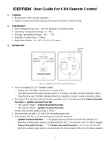
31.
SEQUENCE
CONTROL
FUNCTION
(Figure
3-1)
This
Sequence
Control
is
a
five
sequence
automatic
control,
designed
for
Gas
Tungsten-Arc
Welding
(GTAW).
The
func
tion
of
each
sequence
is
as
follows:
Sequence
A:
Pre-flow
of
gas
and
water;
adjustable
me
chanical
time
of
1/4
to
15
seconds.
Sequence
B:
Start-current;
adjustable
control
and
timer
pre-set
magnitude
of
current
and
time.
Sequence
C:
Weld
Current,
adjustable
control
and
timer
provide
exact
values
of
current
and
time.
Sequence
can
be
manually
controlled.
Sequence
D:
Final
weld
current;
adjustable
control
and
timer
are
pre-set
to
determine
magnitude
and
time
duration
of
current
at
end
of
weld.
Sequence
E:
Post-flow
of
gas
and
water,
adjustable
me
chanical
time
sequence
of
2
seconds
to
3
minutes.
Figure
3-1.
Sequence
Time
Chart
PRE-FLOW
OF
&
WATER
DI
FINISH
1
TA-040
107-6
HIGH
FREQUENCY
SWITCH
CABLE
TO
OUTPUT
TERMINALS
OF
WELDING
POWE~
SOURCE
TA-040
107-2
EMERGENCY
STOP
JUMPER
LINK
TA-OlO
566
Figure
2-3.
Terminal
Block
For
External
Switch
Operation
POST-FLOW
OF
GAS
&
~
tA~
9
ST~RT
~
~C
WftD
V
t7
/(((~/
/___________________
I-,/7777777777/7/
ISH
(((777/7(7
~
\~
~
T~\
TIME
Page
2

3-2.
CURRENT
CONTROL
(Figure
3-2)
The
welding
current
for
each
sequence
is
governed
by
the
setting
of
the
three
Amperage
Controls
which
are
labeled
Start
Weld
Amperage
Control
(sequence
B),
Normal
Weld
Amperage
Control
(sequence
C),
and
Slope
Weld
Amperage
Control
(sequence
D).
The
control
dials
are
calibrated
in
percent.
These
controls
act
as
remote
controls,
in
that
they
are
fine
current
adjustment
of
the
Fine
Current
Adjustment
Controls
on
the
welding
power
source.
The
STANDARD-
REMOTE
Amperage
Control
Switch
on
the
welding
power
source
must
be
in
the
STANDARD
position..
Cu
rrent
Ad
ju
stme~
on
trols
on
the
we
Iding
power
source
must
be
in
the
one
hundred
percent
position
for
maximum
control
of
the
selected
range.
A.
Start
Weld
Amperage
Control
(Sequence
B)
This
control
is
provided
for
selecting
the
start
weld
current
value.
The
control
is
adjustable
and
can
be
set
for
any
value
from
the
minimum
to
the
maximum
of
the
selected
current
range
on
the
welding
power
source.
For
a
normal
start
the
control
should
be
set
for
a
value
less
than
the
normal
weld
(sequence
C)
setting.
B.
Normal
Weld
Amperage
Control
(Sequence
C)
This
control
is
provided
for
selecting
the
normal
weld
current
value.
The
control
is
adjustable
and
can
be
set
for
any
value
from
the
minimum
to
the
maximum
of
the
selected
current
range
on
the
welding
power
source.
C.
Slope
Weld
Amperage
Control
(Sequence
D)
This
control
is
provided
for
selecting
the
slope
weld
current
value.
The
control
is
adjustable
and
can
be
set
for
any
value
from
the
minimum
to
the
maximum
of
the
selected
current
range
on
the
welding
power
source.
For
a
normal
finish
the
control
should
be
set
for
a
value
less
than
the
normal
weld
(sequence
C)
setting.
3-3.
NORMAL-FAST
START
SWITCH
(SCE/SCM-1A
and
2A)(Figure
2-2)
This
switch
provides
a
choice
of
selecting
either
a
normal
or
a
fast
start
of
sequence
B
(start
weld).
A.
Normal
Position
With
the
switch
in
the
NORMAL
position
the
starting
current
will
start
at
a
value
less
than
the
setting
of
the
Start
Weld
Amperage
Control,
but
will
rapidly
increase
to
the
setting
of
the
Start
Weld
Amperage
Control.
B.
Fast
Position
With
the
switch
in
the
FAST
position
the
starting
current
will
start
at
the
value
of
the
Start
Weld
Amperage
setting.
3-4.
AUTOMATIC-MANUAL
SWITCH
(Figure
2.2)
This
switch
provides
a
choice
of
selecting
either
an
automatic
or
semi-automatic
operation
of
the
Sequence
Control.
A.
Automatic
Position
With
the
switch
in
the
AUTOMATIC
position,
the
Sequence
Control
will
operate
automatically
through
all
sequences
with
the
use
of
a
contactor
control
switch
connected
to
the
Con
tactor
Control
Receptacle.
B.
Manual
Position
With
the
switch
in
the
MANUAL
position,
the
timers
of
se
quences
B,
C,
and
D
are
removed
from
the
circuit.
However,
the
weld
sequence
current
value
will
be
controlled
by
the
normal
Weld
Amperage
Control
on
the
Sequence
Control.
Closing
the
contactor
control
switch
will
initiate
sequence
A.
Upon
completion
of
sequence
A
the
weld
sequence
will
be
initiated
automatically.
The
Sequence
Control
will
continue
to
operate
in
the
weld
sequence
until
the
contactor
control
switch
is
opened.
Opening
this
switch
will
extinguish
the
weld
sequence
and
initiate
sequence
E
(post-flow
gas
and
water
time).
GAS
AND
WATER
POST-FLOW
TIME
CONTROL
SLOPE
WELD
TERMINAL
BLOCK
FOR
EXTERNAL
SWITCH
OPERATION
AND
EMERGENCY
STOP
SWITCH
CONNECTION
NORMAL
WELD
TIME
CONTROL
VOLTAGE
CHANGE
OVER
TERMINAL
BLOCK
FOR
CONTROL
TRANSFORMER
Figure
3.2.
Control
Panel
View
TA-040
107-3
OM-540
Page
3

3-5.
MANUALCONTROLOFSEQUENCEC
Provisions
are
provided
for
manual
timing
of
sequence
C
to
allow
continuous
welding
for
any
desired
time.
This
is
accom
plished
by
connecting
an
external
switch
into
the
circuit.
Refer
to
paragraph
2-7
for
information
on
connecting
the
external
switch.
The
Sequence
Control
functions
auto
matically
through
sequences
A
and
B.
but
the
time
duration
of
sequence
C
is
controlled
by
the
external
switch.
Closing
the
external
switch
will
extinguish
sequence
C
and
initiate
the
slope
weld
time
(sequence
D).
3-6.
HIGH
FREQUENCY
CONTROL
(Figure
2-2)
The
high
frequency
is
controlled
through
the
Direct-Air
coupling
jumper
links
and
the
High
Frequency
Switch
labeled
START-OFF-CONTI
NUOUS.
A.
Direct-Air
Coupling
Located
on
each
side
of
the
high
frequency
panel
are
three
terminals
and
one
jumper
link.
The
position
of
the
links
are
labeled
DIRECT
and
AIR.
These
links
provide
facilities
for
connecting
the
high
frequency
transformer
for
either
direct
or
air
coupling
which
governs
the
amount
of
high
frequency
intensity.
To
increase
the
intensity
connect
both
links
in
the
position
labeled
DIRECT.
To
decrease
the
intensity
Connect
both
links
in
the
position
labeled
AIR.
B.
Off
Position
With
the
switch
in
the
OFF
position,
high
frequency
is
re
moved
from
the
weld
circuit.
This
method
is
recommended
for
Shielded
Metal-Arc
Welding
(SMAW).
C.
Start
Position
With
the
switch
in
the
START
position
high
frequency
is
induced
into
the
weld
circuit
as
an
aid
in
starting
the
arc.
When
a
welding
arc
is
established
the
high
frequency
will
automatically
shut-off.
This
method
is
recommended
for
dc
Gas
Tungsten-Arc
Welding
(GTAW).
D.
Continuous
Position
With
the
switch
in
the
CONTINUOUS
position
high
fre
quency
is
induced
into
the
weld
circuit
during
all
three
weld
ing
sequences
or
as
long
as
the
contactor
is
energized.
This
method
is
recommended
for
AC
Gas
Tungsten-Arc
Welding
(GTAW).
SECTION
4
-
SEQUENCE
OF
OPERATION
4-1.
SHIELDED
METAL-ARC
WELDING
(SMAW)
For
Shielded
Metal-Arc
Welding,
check
and
adjust
the
Con
trols
as
follows:
1.
Disconnect
or
shut-off
the
shielding
gas
and
water
sup
plies.
2.
Check
that
sdcondary
connections
are
as
described
in
paragraph
2-2.
3.
Determinal
the
type
of
welding
current
required
(AC,
DCSP
or
DCRP)
and
position
the
Polarity
Switch
or
Current
Selector
Switch
on
the
welding
power
source
accordingly,
4.
Place
the
Current
Range
Switch
on
the
welding
power
source
in
the
desired
current
range.
5.
Rotate
the
Fine
Current
Adjustment
Control
on
the
welding
power
source
to
the
maximum
position.
6.
Rotate
the
Normal
Weld
Amperage
Control
(sequence
C)
on
the
Sequence
Control
for
the
approximate
per
centage
of
weld
current
desired
within
the
range
selec
ted
on
the
welding
power
source.
7.
Place
the
Automatic-Manual
Switch
in
the
MANUAL
position.
8.
On
SCE/SCM-1A
and
2A
Models,
adjust
the
Start
Weld
Amperage
Control
to
approximately
the
same
setting
of
the
Normal
Weld
Amperage
Control
setting.
9.
On
SCE/SCM-1A
and
2A
Models
place
the
Normal-
Fast
Switch
in
the
desired
position
according
to
the
welding
application.
Place
the
High
Frequency
Switch
in
the
OFF
position.
Connect
a
normally
open
switch
into
the
Contactor
Control
Receptacle.
12.
Place
the
On-Off
Power
Switch
on
the
welding
power
source
to
the
ON
position.
13.
Close
the
Contactor
Control
Switch
and
commence
welding.
14.
Readjust
the
controls
as
necessary
for
proper
weld
condition.
4-2.
GAS
TUNGSTEN-ARC
WELDING
(GTAW)
For
Gas
Tungsten-Arc
Welding,
check
and
adjust
the
controls
as
follows:
1.
Check
that
shielding
gas
and
water
Connections
are
as
described
in
paragraphs
2-3
and
2-4.
2.
Check
that
secondary
connections
are
as
described
in
paragraph
2-2.
3.
Determine
the
type
of
welding
Current
required
whether
(AC,
DCSP
or
DCRP)
and
position
the
Polar
ity
Switch
or
Selector
Switch
on
the
welding
power
source
accordingly.
4.
Place
the
Current
Range
Switch
on
the
welding
power
source
in
the
desired
current
range.
5.
Rotate
the
Fine
Current
Adjustment
Control
on
the
welding
power
source
to
the
maximum
position.
6.
Rotate
the
Start
Weld
Amperage
Control,
Normal
Weld
Amperage
Control,
and
the
Slope
Weld
Amper
age
Control
on
the
Sequence
Control
to
the
desired
setting.
7.
Place
the
Automatic-Manual
Switch
in
the
MANUAL
position.
8.
On
SCE/SCM-1A
and
2A
Models,
place
the
Normal-
Fast
Switch
in
the
desired
position
according
to
the
welding
application.
9.
Place
the
High
Frequency
Switch
in
the
START
posi
tion
for
dc
welding
and
in
the
CONTINUOUS
position
for
ac
welding.
10.
Adjust
the
shielding
gas
and
water
pre-flow
and
post-
flow
timers
for
the
desired
time
setting.
PURE
TUNGSTEN
CURRENT_RANGE
Electrode
Dia.
(In.)
ACHF-Argon
DCSPArgon
DCSPHelium
.010
Up
to
15
Up
to
15
Up
to
20
.020 10
to
30
15
to
50
20
to
60
.040
1/16
3/32
1/8
5/32
3/16
20
to
70
50
to
125
100
to
160
150
to
210
190
to
280
250
to
350
25
to
70 30
to
90
50
to
135
60
to
150
125
to
225
215
to
360
350
to
450
450
to
720
140
to
250
240
to
400
390
to
500
500
to
800
1/4
300
to
500
720
to
990
800
to
1100
1%
AND
2%
THOR
IATED
TUNGSTEN
.010
Up
to
20
Up
to
25
Up
to
30
.020
15
to
35
15
to
50
20
to
60
.040
20
to
80
25
to
80
30
to
100
1/16
50
to
140
50
to
145
60
to
160
3/32
130
to
250
135
to
235
150
to
260
1/8
225
to
350 225
to
360 250
to
400
5/32
300
to
450
360
to
450
400
to
500
3/16
400
to
550
450
to
720
500
to
800
1/4
500
to
800
720
10990
800
to
1100
10.
11.
Table
4-1
Guide
For
Selecting
Electrode
For
Gas
Tungsten-Arc
Welding
TA-90
190-3
Page
4

11.
Select
the
proper
size
tungsten
for
the
welding applica
tion
from
Table
4-1.
12.
Connect
a
normally
open
switch
into
the
Contactor
Control
Receptacle.
13.
Place
the
On-Off
Power
Switch
on
the
welding
power
source
to
the
ON
position.
14.
Close
the
contactor
control
switch
and
commence
welding.
15.
Readjust
the
controls
as
necessary
for
proper
welding
condition.
SCM-IA.
2A
SCE-IA,
2A
SEQUENCE
TIMER
FLOW
CHART
S
1
Switch
in
Manual
Position
S
2
Switch
in
Normal
Start
Posit
ion
S
3
Switch
in
Start
Position
p.
u.
-
picks
up
d.c.
-
drops
out
Power
Switch
On
Control
Transformer
Energized
CR1
d.o.By
Operator
I
I
TD1
CR2
d.o.
d.o.
TD5
p.u.
Begins
Time
TD
5
Times
Out
FL
4
Gas
&
Watet
Off
Off
TO
1
p.u.
(No
Effect
in
Manual
Position)
TD5
CR5
pu.
d.o.
(S2
in
Fast
Start
Posit
ionl
Welding
arc
established
as
Point
A
in
Sequence
Flow
Chart
when
II.F.
Switch
is
in
Continuous
Position
and
at
Point
B
when
H.F.
Switch
is
in
Start
Position.
-
Opesator
Control
Relay
-
Gas and
Water
Control
Relay
-
Secondary
Voltage
Sensing
Relay
Start
Time
and
I-I.E.
Start
Control
Relay
-
Start
Rheostat
Control
Relay
CR
6
-
Weld
Rheostat
Control
Relay
CR
7
-
Weld
and
Slope
Time
Control
Relay
CR
8
Slope
Rheostat
Control
Relay
CR
9
-
Stop
Sequence
Relay
Figure
4-1.
SCM/SCE.1A,
2A
Sequence
Flow
Chart
-
Si
Manual
Position
Control
~oltage
Available
I
Gas
&
Water
TO
5
p.u.
On
Begins
Time
a
p
Gas
&
Water
TO
5
Z
On
~
Times
Out~
Operator
Closes
Maintain
Switch
Thxough
RC
1
I
CR1
p.u.
U
I
FL
4
Fan
On
On
PL4
Off
H,F,
On
Primary
Contacror
CR2
p.u.
I
I
Lfi
(Continuous
Position)
w
p.u.
O.C.V.
I
AvaiLable
I
_______________
Gas&Wate.r
PL4
On
On
CR3
p.u.
W
1
Closes
CR6
p.u.
P1,2
On
I
CR
~
R4
Operative
(Weld
I~eosat)
d.o.
CR4
p.u.
I
Welding
Eatablished
CR3
d.o,
CR4
do.
HF,
Off
(Start
Positionl
CR
1
CR
2
CR
3
CR
4
CR
5
1-IF.
Off
(Continuous
Position)
Primazy
~onsactot
W
d.o.
W
Opens
Weld
Terminated
CR6
PL2
R4
d
o~
Off
Inoperative
I~1
I-
C
-i
I.
~~5
2
OM-540
Page
5

SLM-lA~
2A
ICE-IA.
2A
SEQUENCE
TIMER
FLOW
CHART
TD1
p.o.
Begins
Pee
flow
Time
TO
1
fi.j~mes
Our
H.F.On
~timary
Contacror
(Continuous
w
p.u.
Position)
p
T03p.u.
CR6
PCI
Begins
Weld
p.ii.
Ott
Time
I
CR5
R
4
Operative
d.c.
(Weld
Rheostat)
TO
3
P1
R
3
Inoperative
Times
Out
Off
(Start
Rheostat)
CR7
p.o.
p~u.
-
picks
up
d.c.
-
dtops
out
f
I
I
Gas&
Water
TOS
p.o.
P14
On
Beguts
Time
On
Gas
I
Water
TD
S
~
~
Off
.~.
Times
Out
~
Of
f
F
Operation
of
a
Normally
Closed
Switch
at
TE
4
will
stop
the
Sequence
at
any
polor
in
the
Weld
Sequence.
Control
will
revert
to
Position
A
of
the
Flow
Chart,
CR2
pa.
Locks
on
itself
Through
CR
9
Welding
Arc
established
at
this
point
when
H.
F.
Switch
in in
Coorlnuous
Position.
Dotted
lines
show
flow
sequence
with
H.F. Switch
in
Start
position.
NOTE:
TD
2
polls
op
ood
begins
time
at
Point
of
Plow
Chart
wheo
H.P. Switch
is
in
Continuous
Position
and
at
Point
C
when
H.P.
Switch
is
io
Start
Positioo.
CR
S
-
Operator
Control
Relay
CR2
-
Gas
aod
Water
Coorrol
Relay
CR3
-
Secondary
Voltage
Sensing
Relay
CR4
Start
Time
and
H.P.
Start
Coorrol
Relay
CR
5
Start
Rheostat
Conuol
Relay
CR
6
-
Weld
Rheostat
Control
Relay
CR7
Weld
aod
Slope
Time
Control
Relay
CR
9
Slope
Rheostat
Control
Relay
CR
9
Stop
Sequence
Relay
Switch
Operarioo
Connected
to
2
&
3
of
TE
4
Provides
Manual
Coorrol
of
Weld
Time
Duration
Figure
4-2.
SCM/SCE~iA.
2A
Sequence
Flow
Chart
-
Si
Automatic
Position
S
1
Switch
in
Automatic
Position
S
2
Switch
in
Normal
Start
Position
Power
Swiich
On
Control
Transformer
Energired
Control
Voltage
Available
.CR
S
p.u.
at
Point
0
when
S 2
Switch
is
io
Past
Stare
Position
and
R
3
is
operative
during
preflow.
CR
S
p.u.
at
Point
E
when
S
2
Switch
a
In
Normal
Position
and
R
3
-...-,
Is
operative
after
Primary
Contacrm
pulla
up.
Operator
Closes
iomentary
Switch
Through
RC
1
p.o.
~1
Fan
On
CR1
d.o.
Released
by
Operator
Gas
&
Water
B
On
T02
p.o.
Regina
Starr
Time
S
TOS
P14
do.
On
Open
Circuit
coltage
Available
ii
WI
Closes
CR3
p.u.
II
CR4
p.o.
CR5
pa.
I
__________
H.P.
On
P1.
S
R
3
Operative
(Start
Position)
On
(Start
Rheostat).~5
~
Welding
A
c
Established
CR3
d
.0.
TD2
p.o.
Regina
Start
Time
TO
2
Timea
Out
B
I-.
I
I
P11
H.P.
Off
On
(Start
Position)
I
PL2
CR6
I
TO4
p.o.
I
I
CR9
P13
Off
d.o.
S
Begins
Slope
Time
I
p.o.
On
I
R4
Inoperative
TD
4
R
1
Operative
(Weld
Rheostat)
Times
Out
CR
9
(Slope
Rheostat).~
P.y.
Primary
~onractor
W
do.
W
1
Opem
F
S
B
5
S
Weld
Terminated
5
5
5
TD1
P13
CR2
H.P.
Off
d.o.
Off
d.o.
fContlnuoos
s
B
TO
2
TD
5
p~
Position)
d.o.
Begins
Time
TO
1
TO
3
Times
Our
d.o.
a
I
s
P1
4
Gas
&
Water
CR
7
Off
Off
d
.0.
I
CR8
T04
4.0.
d.o.
I
Ch
R
S
Irrnperarloe
d.o.
(Slope
Rheostat)
Make
Ready
W
H.P.
TOl
P13
Page
6

SCM-3A
SCE-3A
SEQUENCE
TIMER
FLOW
CHART
p.s.
-
picks
rip
do.
-
drops
out
I
I
Gis
&
Water
TO
S
pu.
FL
4
Begins
Time
0n
I
I
I
Gas
&
Water
TD
FL
4
0f1
~
Times
Out
Off
HF.
0n
Start
Position)
Welding
arc
established
at
thu
point
when
H.F.
Switch
53
ii
in
Continuous
position.
Dotted
lines
show
flow
sequence
with
H.
F.
Switch
is
Start
posItion.
Welding
A
CR3
d.o.
CR4
d.o.
H.F.
Off
(Start
Position)
FL
1
TO2
p.u.
0n
Begins
Start
Time
TD
2
Times
Out
PL2
CR6
p.u.
CR
5
R
4
Operative
d.o.
(Weld
Rheostat)
...s
FL
1
R
3
Inoperative
Off
(Start
Rheostat)
CR1
do.
By
Operator
CR
6
d.o.
CR5
PL2
p.u.
Off
Inoperative
(Weld
Rheostat)
U
I
CR2
TD1
Primary
do.
d.o.
Contactor
W
d.o.
W
1
TD
2
d.o.
Make
Ready
R3
PL
1
Operative
(Stan
Rheostat)......
TO
p.u.
Begins
Post
Flow
Time
TDS
Times
Out
FL
4
Gas
&
Water
Off
-ncr-
-
Operator
Control
Relay
Gas
and
Waler
Control
Relay
Secondary
Voltage
Sensing
Relay
Starr
Time
and
HF.
Start
Control
Relay
Start
Rheostat
Control
Relay
-
Weld
Rheostat
Control
Relay
-
Weld
and
Slope
Time
Control
Relay
Slope
Rheostat
Control
Relay
Stop
Sequence
Relay
Figure
4-3.
SCM/SCE-3A
Sequence
Flow
Chart
-
Si
In
Manual
Position
SWITCH
S
1
Q4
MANUAL
POSITION
POWER
SWITCH
0N
CONTROL
TRANSFORMER
ENERGIZED
CR5
pu.
Control1vouage
I
Available
Make
Ready
R
3
Operative
PL
1
(Star
Rheostat)
Fan
0n
Operator
Cloas
Maintained
Switch
Thzou
h
RC
1
CR1
p.s.
a
I
TO
1
p.s.
Primary
H.
F
.
0n
Begins
Time
Contactor
W
Switch
S3
I
TO1
Times
Out
(No
Effect
in
Manual
Position)
(Continuoul
Position)
p
-0
Wi
Closes
Make
ready
to
pull
up
TO
2
when
welding
arc
is
established
CR2
Pu.
Gas
&
Water
a-
FL
4
On
~~1
TO
S
d.o.
O.c~.V.
Avatlable
CR3
P.S.
CR
4
pu.
Established
CR1
CR2
CR
3
CR4
CR
S
I
CR6
CR
7
CR
8
CR
9
I..
:6
HF.
0ff
(Continuous
Position)
PL2
OM-540
Page
7

Si
M-3A
ni.L-3A
SLQSENCF
1
OdER
FLOW
CHART
Control
Voltage
Available
Make
Ready
H
3
Opetarice
FL
1
(Stan
Rheostat)
p
CR1
do.
Released
by
Operator
101
p..
Begin.
Prellow
Tune
ID
I
TiniesOui
-
H.P.
tn
(Switch
in
Cont
00002
Position)
ROTE~
ID
2
polls
up
and
begins
tune
at
yowl
of
Flow
Chart
when
H.
F.
Snitch
is
in
Contlouous
position
and
at
point
C
when
H.
F.
Switch
is
ic
Srarr
position.
H.P.
Of!
Switch
in
Start
Position
102
lAnes
Out
J
TD3p.u.
C,
R
Regina
Weld
Time
p.o.
CR
5
04
Operative
do.
(Weld
Rfstnsrat)
PLI
R3
ORf
leopetarioe
(Stan
Rheostat)
ID
3
Times
Out
ltinh
w
TB
4
Connected
1
&
2)
CR7
p.c.
I
I
I
I
1
CR2
P13
121
H.P.
Off
Peimoey
W
d.n.
0ft
dv,
(Cnsrlitoous
Cootactoe
1D2
Pnnitlnn)
d.?.
Begins
ton
do.
FInn
Tone
123
I
I
104
do..
125
CR5
CR8
CR8
do.
Times
Out
P.O.
do.
Make
Ready
H
H.P.
101,
PL3
Rb
hinperarive
(Slope
RRt~af)
Make
Ready
B
3
OperatIve
____________
P11
(bract
Rlrensasr)
P1.4
~ff
Gas
&
Wares
011
p.o.
pnksu
r
J.
o.
.
dropt
G~Lstei
TDS
p.c.
FI!4
SOn
Begins
Tune
On
Os.
&
Water
TD
FL
4
Times
Out
~
Of)
Pan
-On.
Wnlding
arc
estabh,hed
at
his
poini
whnni
H
P.
Swiich
53
is
in
Ccnticucus
position.
Doned
hires
show
flow
scqunocrw
oh
H.
F.
Swnch
5
3
in
Stari~
POSH
icy.
CR
1
-
Operator
Coctrcl
Relay
CR2
-
Oss
and
Water
Control
Relay
CR3
-
Secondary
Voltage
Sensing
Relay
Cn
4
-
Sraat
Time
and
H.
F.
Start
Ccorrol
Relay
CBS
Starr
Rheostat
Control
Relay
CR6
-
Weld
hheoear
Control
Relay
CR1
Weld
and
Slope
Time
Cnnttcl
Selay
CR
8
-
Slope
Rheostat
Control
Relay
CR8
-
Srop
Sequence
Relay
-
Switch
operation
connected
to
2
&
3
o)
TE4
provides
manual
control
o)
weld
ume
duration.
Figure
4-4.
SCM/SCE-3A
Sequence
Flow
Chart
-
Si
In
Automatic
Position
SWITCII
5
I
IN
AVTOhIATIL
POSITION
R)HER
SWPICII
OS
CONTROL
TRAhSF~MER
Rt1EHCIZEO
CO
S
p.u.
Operator
~%_~__
-
Momentary
Switch
Through
bCl
CR
I
pu.
Operation
of
a
tlntma
lIp
Ccrcd
uuoi
Ii
at
TE
4
will
stop
tin
se
quccic
at
snip
peutt
in
the
oe
Id
sequence.
Control
will
truce
to
position
S
of
r
lie
FInn
Chart.
S
CR0
P.O.
Locks
on
hsell
Through
CR3
Ca.
&
Waier
S
3
C
T02
~
Peimar1,
H
Begwrs
Starr
Time
Contractor
pu.
TO
S
IL
4
d.c.
llc
Open
Circuit
coltsg.
Acailable
CR3:
pu.
CR4
P.O.
H.P.
Oc
(Stan
Position)
WeMmg
A;o
Established
CR3
de
CO
4j2_kE~)
PL~l
102
on
Regma
Stan
Time
P1
S
H
H
3
S
H
0
CBS
CRR
Remains
do.
Open
Rh
htoperar
foe
(Weld
Rfreosrat)
124
p.R.
hegms
slope
124
lIme.
Oor
CR9
pu.
P12
CR8
PL53
Off
p.o.
On
BS
Opera
rice
(Slope
Rfiecsrat)4
Weld
Teemonared
Page
8

SCMSA
sUE-IA
SEQUENCE
TIMER
El
r)W
(hART
Switch
Si
in
Manual
PoSition
(Starr
80
Volt
Position)
2
&
3
for
Switch
Operation
S2
Start
Position
(H.
F.
Switch)
p.::.
pt
ha
up
-
druipt
Suit
POWER
SWITCH
0N
CR
S
pu.
TD
S
pu.
I
I
I
I
TI)
S
Times
Out
R
3
Operative
Make
Ready
I
(Start
Rheostat)
so
Energize
PL
1
Gas
&
Water
I
Flow
Stops
~
I
I
PL4
Goes
1
Out
I
I
I
I
PI.
4
Gas
&
Water
TI)
6
Motor
Runt
CR
10
pu.
Lights
Flow
Starts
Continuously
Up
CR
17
p.u.
H.F.
By.Pass
Circuit
Closed
NOTE:
CR
10
insures
by.pass
closed
Make
Ready
to
Enet
before
Hl.F.
is
on.a
short
gize
High
Frequency
time
delay
of
CR
17
insures
H.F.
off
before
bypals
opens.
CR
9
pu.
CR
14
pu.
(provides
short
nine
delay
to
insure
CR
2
lockt
ott
itself.
Opens
Circuit
to
TI)
I
Contactor
and
PL
3
(Control
Safety
Relay)
Make
Ready
to
Energize
CR
2
-
CR
2A
-
CR28
-
TDI
1
pu.
(Held
Closed
by
Operator
through
RC
2)
TI)
6
BeginS
Time
W
Conta
TI)
6
Times
Out
Welding
CR
10
d.o.
CR
17
d.o.
After
1fF.
Off
Time
Delay
p
By-Pass
Open
-
Operator
control
relay
-
Interlocking
control
relay
-
Control
relay
-
Control
relay
-
Overvoltage
sensing
relay
H.F.
signal
relay
-
Control
relay
for
start
rheostat
-
Control
relay
for
weld
rheostat
-
Slope
control
relay
-
Control
relay
for
slope
rheostat
Safety
control
relay
-
H.F. time
delay
relay
-
Differential
voltage
sensing
relay
Contactor
drop
out
time
delay
relay
Interlocking
control
relay
Time
delay
elay
(or
CR
2
inrerlock
-
Start
165
volt
control
relay
-
HF.
control
relay
-
HF.
By
Past
Time
Delay
Relay
PU
Lights
Up
PL
2
Lights
Up
TD1
CR28
do,
do.
Primary
CR11
TD6
Contactor
d.o.
W
d.o.
I
CR12
d.o.
d.o.
CR6
PC2
do.
Off
TDI
pu.
CR2B
pu.
I
I
TI)
1
Make
Ready
to
Times
Out
Energize
hF.
Couttactor,
HF.
CR2A CR2
CR14
do.
d.o.
pu.
I
I
1
Voltage
TI)
5
CR
9
p.u.
p.u.
Begins
Time
TD
S
Timm
Out
Gas
&
Water
PL
4
Shuts
Off
Goet
Of
CR
14
do.
After
Time
Delay
~1
CR
16
U
a.
Figure
4-5.
SCM/SCE-5A
Sequence
Flow
Chart-Si
In
Manual
Position
CR2
p.u.
I I I
CR9
d.o.
TDSd.o.
PL4
Gas&
Lights
Water
Ott
Up
I
I
80
VOC
Available
CR
2A
pu.
Make
Ready
to
Energize
CR
13
CR16
pu.
HF.
0n
CR
I
CR
U
p.u.
p.u.
:tor
p.u.
Ire
Esrabli.ihed
Timer,
&
CR
11.
W
1
Closes
TD2
Begins
Time
TD
2
Times
Out
-1
CR6
pu.
I
I
R4
Operative
CR
d.o
Fl.
1
Goes
O~it
R
3
Ino~erative
)
I
CR
1
do.
(Released
by
Operator)
CR
1
CR
2
CR
2A
CR
25
CR
3
CR4
CR
5
CR
6
CR
7
CR
8
CR
9
CR
10
CR
11
CR
12
CR
13
CR
14
CR
15
CR
16
CR
17
Welding
Arc
Extinguil
d.o.
Reducer
CR
10
Open
p.u.
CR
17
By
Pass
p.u.
Closed
I
ed
CR5
R4
p.u.
Inoperative
R3
Operative
OM-540
Page
9

sCM-IA
SCE-5A
SEQUENCE
TIMER
FLOW
CHART
CR3
pu.
TDt
pu.
I
I
TD
5
Times
Out
R3
Operative
Make
Ready
I
(Start
Rheostat)
to
Energize
Gas
&
Water
PL
1
Flow
Stoll~.
PL
4
Goes
Out
CR2
pu.
and
Locks
on
itself
through
CR
9
TO
6
Begins
Time
TO
6
Times
Out
CR10
d.o.
CR
17
do.
I-I.E.
Off
After
Time
Delay
By-Pass
Open
Unintenrior~al
Arc
Outage
(One
cycle
or
less)
80
VOLTS
Open
CR
2A
p.u.
Circuit
Available
p
Make
Ready
to
Energize
CR
13
CR
6
CR
7
CR
8
CR
9
CR
10
PL
1
Lights
Up
CR
11
CR
12
CR
13
,
CR14
PL2LightsUp
CR13
CR
16
CR
17
CR14
pu.
)Ptovides
short
time
delay
to
insure
CR2
locks
ott
itself)
CR
14
d.o.
after
Time
Delay
-
Control
relay
for
weld
rheostat
-
Slope
control
relay
Control
relay
for
slope
rheostat
-
Safety
control
relay
-
H.F.
time
delay
relay
Differential
voltage
sensing
relay
-
Contacror
drop
out
time
delay
relay
-
Interlocking
control
relay
Time
delay
relay
for
CR
2
interlock
-
Start
165
volt
corttrolreIay
-
N.E.
control
relay
N.E.
By
Pass
Time
Delay
ReLay
Figure
4-6.
SCM/SCE-5A
Sequence
Flow
Chart
-
Si
In
Automatic
Position
Switch
Si
in
A
atoms
tic
Position
Link
1
&
2
for
Timer
(Start
80
Volt
Position)
S2
Start
Position
(H.
F
Switch)
POWER
SWITCH
0N
p.o.
picks
up
d.
o.
drops
out
I
I
P
PL
4
Gas
&
Water
TO
6
Motor
Runs
Lights
Flow
Statti
Continuously
CR
10
pu.
CR
9
pu.
CR
17
pu.
Opens
Circuit
so
TO
1~
Contactor
and
PL
3
(Control
Safety
Relay)
H.P.
By
Pass
Circuit
Closed
CR
10
insures
by
pass
closed
Make
lady
to
Ecer
NOTE
before
H.F.
is
on.a
short
gize
High
Frequency
time
delay
of
CR
17
insures
HF.
off
before
by-pass
opens.
WELDING
TORCH
PRESET
OVER
WORK
Operator
Closes
Momentary
Switch
Through
RC
2
CR
1
p.u.
CR9
TD5
CR
1
d.o.
PL4
Gas
&Water
do.
d.
o.
by
Operator
Lights
Up
Make
Ready
so
Energize
CR2-
CR2A
-
CRIB
-
TO
1
CR
1
Operator
control
relay
CR
2
-
Interlocking
control
relay
CR
2A
-
Control
relay
CR
28
-
Control
relay
CR3
-
Overvoltage
sensing
relay
CR4
HF.
signal
relay
CR
5
Control
relay
for
starr
rheostat
CR2B
p.o.
HF.
Make
Ready
to
Energize
High
Ere
quzuCy
Contactor,
H.P.
Timer&CR11
T01
pu.
TDJ
TimesOur
CR16
p.o.
High
Frequency
On
CR11
~p.u.
~
(Secondary
Voltage
Drops
as
a
Result
of
H.F.
P
Arc.
Differential
Voltage
Pulls
Up
CR
11)
CR12
pu.
~
1
I
w
Contacor
~.u.
II
Welding
Arc
Established
TD2
Begins
Time
TD2
TmmosOut
TD3
BeginaTmme
CR6p.u
I
1
B
4
Operative
CR
5-
d.o.
Weld
Rheostat
Tb
3
Times
Out
~i
1
Goes
Out
B 3
Inoperative
TD4
BeginaTime
CR7
pu.
CR
3
pu.
CR4
P~U
WeldCycleReverts
to
Start
Control.
CR10
t.U.
Tinner
TO
2~&R3
H.P.
On
Approximately
40
Cycles
Arc
Re-established
CR3
d.o.
I
CR4
do.
I
Welding
Arc
CR
10
d.o.
H.F.
Off
p
I
__p
By-Pass
Open
Switch
Operation
Connected
to
2
&
3
of
TE
4.
Provides
Manual
Control
of
Weld
Time
Duration.
CR
B
p.u.
CR
6
do.
PL
2
Goes
Out
PL
3
Lights
CR
S
CR7
Locks
on
Itself
Operative
R4
Inoperative
Remains
Open
Through
WI
4
Times
Out
CR
9
pu.
I
P
cLot
d.o.
CR2
d.o.
CR
2A
d.o.
TD
1
d.o.
TO
S
Begins
Time
TD5TimesOut
I
Make
Ready
2
Gas
&
Water
P1.
~
For
HF.
Shuts
Off
Goes
Out
Voltage
Reducer
Open
I
I
I
I
I
TO
6
d.c.
PL
3
CR
16
CR
2B
TO
2
CR.
1~
~
Goes
d.o.
d.o.
d.c.
Out
-
I
CR11
T03
I
CR
17
By-Pass
Closed
p.u.
d.c
do.
TD4
P
CR2
d.c.
CR7
do.
d.c.
CR5
CR8
pu.
d.c.
R3
R5
Operative
Inoperative
Page
10

SECTION
5
MAINTENANCE
5-1.
MAINTENANCE
SAFETY
reiunr.]1
Be
sure
the
branch
circuit,
or
the
main
disconnect
switch
has
been
opened
before
attempting
any
inspect
ion
or
performing
any
work
inside
the
welding
power
source
or
the
sequence
control.
Placing
the
power
switch
on
the
welding
power
source
in
the
OFF
posi
tion
does
not
remove
electrical
power
from
the
switch
terminals.
5-2.
HIGH
VOLTAGE
CAPACITORS
These
capacitors
require
no
attention
and
are
rarely
a
source
of
trouble.
A
defective
capacitor,
however,
is
evident
usually
by
the
housing
or
evident
of
oil
leakage
in
certain
cases.
Any
local
radio
repair
shop
can
readily
determine
the
condition
of
the
capacitors.
(If
one
of
the
high
voltage
capacitors
should
fail,
operation
may
be
continued
with
one
capacitor
until
a
new
one
can
be
secured.I
In
order
to
prevent
excessive
over
load
on
the
remaining
single
capacitor,
the
spark
gap
point
setting
should
be
reduced
to
about
.004.
5-3.
SPARK
GAP
The
spark
point
and
air
gaps
can
be
inspected
by
opening
the
door
of
the
Sequence
Control.
The
spark
air
gaps
are
factory
set
at
.008
inch.
It
will
be
necessary
to
readjust
the
spark
air
gap
setting
due
to
extended
operation.
Readjustment
of
the
spark
air
gap
is
also
indicated
when
intermittent
operation
of
the
high
frequency
is
noted.
Usually
this
occurs
when
the
spark
air
gap
setting
has
increased
in
excess
of
.012
inch.
~ning
of
the
spark
&
r
gaps
d
ue
to
n
ormal
ope
ra
tion,
may,
if
not
corrected,
increase
the
loading
of
the
high
voltage,
capacitors,
thus
contributing
to
their
premature
failure.
Cleaning
or
dressing
the
points
is
not
recommended
as
the
material
at
the
gap
area
is
tungsten.
The
entire
point
should
be
replaced
when
the
tungsten
section
has
disappeared.
5-4.
SPARK
AIR
GAP
ADJUSTMENT
To
readjust
the
spark
air
gaps,
proceed
as
follows:
(Fig.
4-1)
A.
Loosen
screw
(A)
on
both
sides.
B.
Place
an
.008
inch
feeler
gauge
in
spark
air
gap
area
(C).
C.
Apply
slight
pressure
against
spark
point
(B)
so
feeler
gauge
is
held
firmly
between
the
two
points.
0.
Tighten
screw
(A).
5-5.
BY-PASS
PANEL
The
purpose
of
the
by-pass
panel
is
to
reduce
the
high
fre
quency
feedback
into
the
transformer
of
the
welding
power
source.
A
defective
capacitor
in
this
circuit
would
reduce
high
frequency
output
and
might
be
evident
by
loss
of
oil
from
the
capacitor
case.
If
in
doubt
as
to
condition
of
the
capacitors,
have
them
checked
at
a
radio
repair
shop.
The
resistors
in
the
circuit
would
show
evidence
of
failure
if
they
are
cracked.
Failure
in
this
circuit
is
rare
and
would
be
sus
pected
only
as
a
last
resort.
SECTION
6
-
TROUBLESHOOTING
The
data
listed
here,
discusses
some
of
the
common
problems
which
may
occur
in
this
sequence
control.
A
little
thought
will
probably
solve
the
problem
through
the
information
provided.
The
assumption
of
this
data
is
that
a
proper
welding
condition
had
been
achieved
until
trouble
developed.
In
all
cases
of
equipment
malfunction,
the
manufacturers
recommendations
should
be
strictly
followed.
If
after
checking
the
following
data
the
trouble
has
not
been
reme
died,
it
is
recommended
that
a
serviceman
be
called.
It
is
recommended
that
the
circuit
diagram
be
used
for
reference
during
troubleshooting.
TROUBLE
PROBABLE
CAUSE
REMEDY
Normal
output.
No
high
frequency.
Incorrect
spark
air
gap.
Check
setting
for
.008
inch.
High
frequency
switch
in
off
position.
Check
switch
position.
Shorted
high
voltage
capacitor..
Replace
capacitors.
Normal
output.
Low
high
frequency.
Incorrect
spark
air
gap.
Check
setting
for
.008
inch.
High
frequency
leaks.
Check
all
connections
for
high
frequency
leaks.
Incorrect
direct-air
coupling.
Check
that
both
links
are
connected
for
the
same
coupling.
Erratic
weld
current.
Poor
tungsten.
Check
tungsten
and
replace
if
contaminated.
Incorrect
polarity.
Check
polarity.
Incorrect
welding
cable
size
or
loose
connections.
Check
for
proper
weld
cable
size
(See
paragraph
1-2.)
Tighten
all
welding
cable
connections.
Poor
ground
at
workpiece.
Check
ground
connections.
Figure
5-1.
Spark
Air
Gap
Adjustment
TA-020
623
.
OM-540
Page
11

TROUBLE
PROBABLE
CAUSE
REMEDY
Contactor
pulls
in.
Incorrect
operating
voltage
of
CR3
relay.
Adjust
slider
on
R2
resistor
so
CR3
relay
pulls
in
on
open
circuit
voltage.
Weld
current
does
not
shut
off.
Incorrect
operating
voltage
of
CR3
relay.
Adjust
slider
on
R2
resistor
so
CR3
relay
drops
Out
when
welding
arc
is
initiated.
Contactor
does
not
pull
in.
Blown
fuses
in
control
circuitry.
Check
fuses.
Figure
6-1.
Circuit
Diagram
For
200,
300
&
400
Ampere
DC
Arc
Welding
Power
Source
With
SCE-1A
Sequence
Control
32
44
TEl
T1
LO~O~o-----------
--
L
~
~
r
TE1
W
23OVr
LO_Z~o~o___s_______
II
.
460V~
I
WELDING
230V1
~a3OV
1460V
SEQUENCE
MACNINE
44
3
TE3lj~9
~?
I!(~TE2
TIMER
_____
____
\~
~
PCI
CR
C
B
~36~7
MAI
52
36
FO
:sEc.
B
72
I
,.,
~
A
iii
IC
~
:::
H.
i~
B
~
_
I
I
IA
16
22
_____________
ID
Ill
~
I
r~
III
23
I
A
;
I
251
14
14
145R1
14
____
26
00000
30
30V
3
PCI
233
CR5
START
234
235
1,1
2
3
4
0000000
~
61*
1ISv
h4
EMERGENCY
~
RC3*
CR1
~
CR
~
2,14,15
5
2/1
9
I
M
~TP~LOCATED
IN
OR---
I
CR9
WELDING
MACHINE
CR5
CR6
WELD
236
237
28
ELECT
53
REV
SIR
START
HFO~_~
Pt
C~~QQQj
~
I
TWISTED
/
PAIRS
I
29
8,10
T~
0~
P7
VOLTMETERS
RF
FILTERS
WORK
8,8
5
IOPTIONAL-ESTRA(
l_
0
~o.
IR
RD
3,5031
Ir~i~Ii3i
I
Ill
1C3–
~
T3
L__1T1___J
2~,~RFC
CR
8,19,90.20
ELECTRODE
WORK
I?
18
I
ID,
CR4A
~~o51CR~,PL
START
I
20
I
\52
b.NOPMALI
276
CR
C-FAST
I
CR85
~j9
CR3
I
V8
LOPE
~
_I
21
~+L
1231
CR~
___________
22
CR9
l_~:~J.
8
220
221
5
SEQLI
E
NC
E
CR31
TD2
SA
TEl2
~
1+~~4
23
256
3
2A
1-
PRCFLOW-GSW
2-
START
TIME
2
I
3-
WELD
TIME
C
4-SLOPETIME
3<
Al
W
R7226
CR
5-
PO5TFLOWGIW
~l~l
10
8
~E~0
t,JUI
*Op1IONAL..EXIRA
~
~,
2
~PL
WITH
PC3
CR73
80
.6-In
60
-~
37322
34420
..(RE
72
3
~PL
000000
iT
13
.
249
61*
20
44
.91
.90
I
4
2.9039460
COM
0000
000
0
II.
-
21
TE2
TE3
CR2
ws1
IS
251
4
209
000
31
245
7246207208
C
Si
00000
6
4T
TO
RC9
U
RHS-2
8,10,11
21,22,22
2,4
16
I
-
~
-
~WL
REMOTE
CONTROL
IOPTIONAL
ESTRAI
CR
-
GROUND
(WNT
1
B-BRASS
(VI
C
-
COPPER
(5)
Circuit
Diagram
No.
CB.900
529-13C
Page
12
Page is loading ...
Page is loading ...
Page is loading ...
Page is loading ...
Page is loading ...
Page is loading ...
Page is loading ...
Page is loading ...
Page is loading ...
Page is loading ...
Page is loading ...
Page is loading ...
Page is loading ...
Page is loading ...
Page is loading ...
Page is loading ...
Page is loading ...
Page is loading ...
Page is loading ...
Page is loading ...
Page is loading ...
Page is loading ...
/