Duratech DURAPRO-12 User manual
- Category
- Above ground pool accessories
- Type
- User manual
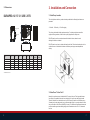
The Duratech DURAPRO-12 is a versatile and energy-efficient swimming pool heat pump designed to keep your pool at a comfortable temperature, extending your swimming season. With its advanced inverter technology, it adjusts its operation to match the heating requirements, resulting in quieter operation, reduced energy consumption, and precise temperature control. Equipped with a durable PVC & Titanium tube heat exchanger, it can withstand prolonged exposure to pool water, ensuring long-lasting performance.
The Duratech DURAPRO-12 is a versatile and energy-efficient swimming pool heat pump designed to keep your pool at a comfortable temperature, extending your swimming season. With its advanced inverter technology, it adjusts its operation to match the heating requirements, resulting in quieter operation, reduced energy consumption, and precise temperature control. Equipped with a durable PVC & Titanium tube heat exchanger, it can withstand prolonged exposure to pool water, ensuring long-lasting performance.


-
 1
1
-
 2
2
-
 3
3
-
 4
4
-
 5
5
-
 6
6
-
 7
7
-
 8
8
-
 9
9
-
 10
10
-
 11
11
-
 12
12
-
 13
13
-
 14
14


Duratech DURAPRO-12 User manual
- Category
- Above ground pool accessories
- Type
- User manual
The Duratech DURAPRO-12 is a versatile and energy-efficient swimming pool heat pump designed to keep your pool at a comfortable temperature, extending your swimming season. With its advanced inverter technology, it adjusts its operation to match the heating requirements, resulting in quieter operation, reduced energy consumption, and precise temperature control. Equipped with a durable PVC & Titanium tube heat exchanger, it can withstand prolonged exposure to pool water, ensuring long-lasting performance.
Ask a question and I''ll find the answer in the document
Finding information in a document is now easier with AI
Related papers
Other documents
-
 Kaisai KHX-14PY3 Operating instructions
-
 Kyocera Dura Series User DuraPro E4277 U.S. Cellular User manual
-
 Wooster 0F51190046 Specification
-
Innotek FieldPro Beeper Owner's manual
-
 Monet PC5220 User manual
-
Astral Pool 78542 Installation And Operating Instructions Manual
-
INVT GD300-21 Series VFD User manual
-
 EVO HEAT EVO Force-i Inverter Pool and Spa Heat Pump User manual
-
CTC Union GSi 12 Installation and Maintenance Manual
-
Evo Force-i Owner's manual


