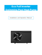
SUN05

Duratech SUN05 User manual

  • Hello! I've reviewed the user manual for the DURATECH Sun Spring series heat pumps: SUN05, SUN08 and SUN12. This manual covers everything from installation and wiring, to operation, maintenance, and troubleshooting. I'm familiar with the features, including the parameters interface, time delay for the compressor and safety precautions. I am ready to assist you with any queries you might have about these products. Feel free to ask!
  • What should I do if the unit has been tilted?
    Where should the heat pump be installed?
    What should I do if there is a water leak?
    What should I do if my heat pump is not working properly?
    How can I verify that the water drainage is condensation?
Manual
SUN05
SUN08
SUN12
Sun Spring
Manual
3
ENG
2
Box contents.......................................................................................................................
Dimensions.........................................................................................................................
1. Speci cations..................................................................................................................
1.1 Performance data Sun Spring...................................................................
2. Preface...........................................................................................................................
3. Safety information..........................................................................................................
4. Preparing the heat pump for use....................................................................................
4.1 Typical set-up.............................................................................................
4.2 Water connection kit.................................................................................
4.3 Installation of the tubing............................................................................
4.4 Electrical wiring..........................................................................................
5. Be aware of....................................................................................................................
5.1 Heat loss....................................................................................................
5.2 Condensation.............................................................................................
5.3 Unobstructed space...................................................................................
5.4 Time delay of compressor..........................................................................
6. Operation and use..........................................................................................................
6.1 Before operation.........................................................................................
6.2 Initial startup...............................................................................................
6.3 General interface........................................................................................
6.4 Parameter interface....................................................................................
6.5 Parameter list............................................................................................
6.6 Error interface.............................................................................................
6.7 Error parameter interface...........................................................................
6.8 Error list.....................................................................................................
6.9 Trouble shooting guide...............................................................................
7. Wiring diagrams..............................................................................................................
7.1 Wire control interface diagram Sun Spring................................................
7.3 Piping diagram and de nition Sun Spring..................................................
8. Maintenance and inspection...........................................................................................
8.1 Water chemistry..........................................................................................
9. Winterizing......................................................................................................................
9.1 Spring startup.............................................................................................
10. Environment..................................................................................................................
11. Service..........................................................................................................................
12. Warranty........................................................................................................................
3
3
4
4
6
6
7
7
8
9
9
10
10
10
10
11
11
11
11
12
13
14
15
15
16
17
18
18
19
20
20
21
21
21
21
22
Table of contents Box content
Manual
Heat pump Sun Spring
Connection kit
456mm
87mm
87mm
456mm
467mm
467mm
530mm750mm
90mm90mm
SUN05 / SUN08
SUN12
Dimensions
x2
5
ENG
4
* Advised pool volume for an entirely insulated pool, with cover, free from wind and exposed to the sun.
UNIT SUN05 SUN08
Advised Pool volume* m312 25
Operating air temperature °C 4 ~ 40
Air 27°C / Water 26°C / Humidity 80%
Heating Capacity kW 5,02 8,1
Btu 17129 27637
Consumed power kW 0,686 1,01
COP 7,31 7,96
Air 15°C / Water 26°C / Humidity 70%
Heating Capacity kW 3,64 5,8
Btu 12420 19790
Consumed power kW 0,639 0,972
COP 5,69 5,97
Power supply 230V / 50Hz / 1 Phase
Electronic Controller Colour LCD
Nominal Running current A3,1 5,1
Max Current A 5 7
RCD - Rated current A 10 EU/UK/SWISS 10 EU/UK/SWISS
RCD - Leakage current mA 30
Condensor Titanium Heat Exchanger / NoFrost
Compressor quantity 1 1
Compressor type Rotary Rotary
Refrigerant R32
Refrigerant weight kg 0,45 0,74
Fan quantity 1 1
Fan power input W 70 80
Fan rotary speed RPM 950 1200
Fan direction Vertical
Noise at 10m dB(A) 44,2 43,8
Water connection mm 38 38
Water ow range m3/h 3 - 12 4 - 12
Unit net dimensions (L*W*H) mm See dimensions on p3
Unit shipping dimensions (L*W*H) mm 470x490x550
Net weight kg 24,7 32
Shipping weight kg 25,7 33
1. Specications
* Advised pool volume for an entirely insulated pool, with cover, free from wind and exposed to the sun.
UNIT SUN12
Advised Pool volume* m338
Operating air temperature °C 4 ~ 40
Air 27°C / Water 26°C / Humidity 80%
Heating Capacity kW 12,2
Btu 41628
Consumed power kW 2,068
COP 5,9
Air 15°C / Water 26°C / Humidity 70%
Heating Capacity kW 9
Btu 30709
Consumed power kW 1,837
COP 4,9
Power supply 230V / 50Hz / 1 Phase
Electronic Controller Colour LCD
Nominal Running current A 9
Max Current A 12
RCD - Rated current A 16 EU/SWISS & 13 UK
RCD - Leakage current mA 30
Condensor Titanium Heat Exchanger / NoFrost
Compressor quantity 1
Compressor type Rotary
Refrigerant R32
Refrigerant weight kg 0,95
Fan quantity 1
Fan power input W 80
Fan rotary speed RPM 1200
Fan direction Vertical
Noise at 10m dB(A) 44,7
Water connection mm 38
Water ow range m3/h 5 - 12
Unit net dimensions (L*W*H) mm See dimensions on p3
Unit shipping dimensions (L*W*H) mm 470x490x770
Net weight kg 45,7
Shipping weight kg 46,7
1.1 Performance data Sun Spring
7
ENG
6
4.1 Typical set-up
The factory provides the heat pump and connection kit. Other parts, including a contingent by-pass must be
provided by the user or installer. The heat pump should be located 2m (recommended) away from the swimming
pool. The longer the distance from the pool, the greater the heat loss from the piping.
4.1 Typical set-up
The factory provides the heat pump and connection kit. Other parts, including a contingent by-pass must be
provided by the user or installer. The h
eat pump should be located 2m (recommended)
away from t
pool. The longer the distance from the pool, the greater the heat loss from the piping.
4. Preparing the heat pump for use
Valve
Water supply
Water outletOutlet valve
Inlet valve
Bypass valve (recommended)
Filter
Water inlet Water pump
Swimming Pool
Water treatment(2)
Put the heat pump on a  at, solid base. Tilting the heat pump for max 3° is allowed.
Install silent blocks in order to avoid vibrations and noise.
All feeding of water treatment to the pool water has to be done downstream of the heat pump(2).
It is normal for condens water to come out of the heat pump. This is not a leak or fault with the unit. If the
humidity is very high, the condens water could be a number of liters a day. Please  nd more information
about condensation in section 5.2.
Always keep the heat pump in upright position. If the unit has been tilted, then wait 24h before starting the
heat pump.
Heat pump
Inlet valve
Filter
Swimming Pool
Heat pump
2 Meter (recommended)
It is recommended to install a by-pass for easy maintenance.
2. Preface
In order to provide our customers with a high quality and reliability, this product has been made to
strict production standards. This manual includes all the necessary information about installation,
debugging, discharging and maintenance. Please read this manual carefully before you open or
maintain the unit. The manufacturer of this product can not be held responsible if someone is
injured or the unit is damaged, as a result of improper installation or maintenance. It is vital that the
instructions within this manual are adhered to at all times. The unit must be installed by a quali ed
person.
The heat pump will always perform very well, provided the following elements are present
1. Fresh air 2. Electricity 3. Swimming pool water
Please read these instructions carefully before using the heat pump and keep them for future reference:
1. Always keep the unit upright. If the unit has been tilted or put on its side, wait 24h before starting the heat pump.
2. Put the unit on a  at, solid base. Tilting the heat pump for max 3° is accepted.
3. Do not drop the heat pump.
4. The heat pump must always be installed outdoors.
5. Check if the voltage indicated on the heat pump corresponds to the local mains voltage before you connect the
unit. Please  nd more information about the electrical connection in section 4.4
6. Do not pull any electrical cable, sensor or tubing with unnecessary force.
7. Do not wrap any cable around the heat pump.
8. Do not use the heat pump in combination with a transformer.
9. If the heat pump is damaged during transportation, it must be replaced, please contact your service centre or
similarly quali ed persons in order to avoid a hazard.
10. Always make sure the water connections of the heat pump are properly locked before you start using the
machine.
11. Never insert objects directly into the fan, as this will cause it to become blocked and damaged.
12. The evaporator  ns must not be damaged.
13. This heat pump is not intended for use by persons with reduced physical, sensory or mental capabilities, or
lack of experience and knowledge, unless they have been given supervision or instruction concerning use of the
heat pump by a person responsible for their safety.
14. Children should always be supervised to ensure that they do not play with the heat pump.
15. Disconnect electricity when the heat pump is not in use and before cleaning.
16. The heat pump should be serviced only by a quali ed service person. Contact your nearest authorized service
facility for examination, repair or adjustment.
17. If the supply cord is damaged, it must be replaced by the manufacturer or your service agent or similarly
quali ed person in order to avoid a hazard.
18. Please contact your dealer if your swimming pool heat pump is not working properly. There might be a leakage
when the heat pump does not heat the swimming pool water. The R32 refrigerant gas is safe when there is a
leakage although re can occure when a ame, heating device or stove gets in contact with the gas. Stop using
your swimming pool heat pump until a quali ed service technician has con rmed that the leak has been repaired.
19.Make sure that there is a circuit breaker for the unit, lack of a circuit breaker can lead to electrical shock or  re.
20. The heat pump is equipped with an over-load protection system. It does not allow for the unit to start for at
least 3 minutes from a previous stoppage.
21. The condens water is not suitable for a potable water connection.
3. Safety information
9
ENG
8
Although the heat pump is electrically isolated from the rest of the pool equipment, this only prevents the
passage of electricity to or from the pool water. Grounding the unit is still required to protect yourself from
short circuits inside the unit. Provide an adequate ground connection.
OUT - Water connection from heat pump:
Typical water pipe from heat pump to water treatment system.
IN - Water connection to heat pump:
Typical water pipe from  lter system to heat pump.
You should always switch off the heat pump immediately when the RCD indicator is turned “OFF”.
Be extremely careful when pressing “RESET” after a failure because there might still be a problem.
The controller of the Sun Spring heat pump
has a memory so that the settings are retained
even if the power is switched off and on. This
makes it possible to operate the heat pump with
a timer. The timer must be installed between the
heat pump and the RCD plug, see picture. The
installation must be carried out by a certi ed
electrical installer in order to guarantee quality
and safe operation.
Test the RCD before usage as follows:
1. Plug the RCD into a  xed socket
2. Press the “RESET” button. The indicator should be “ON”.
3. Press the “TEST” button. The indicator should be “OFF”.
4. Press the “RESET” button again to start using the heat pump
4.4 Electrical wiring
4.3 Installation of the tubing
The heat pump should be located 2m (recommended) away from the swimming pool. The longer
the distance from the pool, the greater the heat loss from the piping. The piping to and from the heat
pump need to t the chosen connections. The pipes can be glued, clamed or screwed onto these
water connections and can be made out off hard or  exible PVC. Always install piping intended for
swimming pool use and use the correct glue to put them together.
4.2 Water connection kit
The factory provides the water connecting kit. This kit consists of 6 parts, with part 1 and 2 as main
parts. The parts 3 to 6 can be swapped so that the connection can be made according to the speci c
requirements of the pool. So in total there are 4 possible options for connecting the water pipes, as
shown below.
1
1 1
1 1
2 2
2 2
3 4
5 6
3
4
2
5
6
1. Custom thread to connect part 2
2. Custom thread to connect part 1 &
BSP G1 1/2” straight external pipe thread
3. Hose connection diameter 38mm & diameter 32mm
4. BSP G 1 1/2” straight internal pipe thread
5. Diameter connection tube 50mm (metric)
6. Diameter connection tube 48mm (imperial)
Glue connection
50mm (metric) 48mm (imperial)
Glue connection
Thread connectionClamping connection
Thread connection
to heatpump
Always check if the voltage from the network corresponds with the operating voltage of the unit.
Your typical swimming pool con guration can be controlled using a timer. Please contact your
service centre or similarly quali ed persons to change the RCD into a standard electrical plug. A
timer can be put in between the heat pump AND pool circulation pump once a standard electrical
plug is installed. Using a timer; The heat pump and pool circulation pump will start up automatically
as soon as power is broken and restored. The heat pump remembers its last status and starts up
with last remembered settings.
+ +
+ +
+ +
+ +
11
ENG
10
5.4 Time delay of compressor
The heat pump is equipped with a 3 minute built-in solid state restart delay once the compressor is
turned off and a 1 minute buit-in solid state compressor running time. Both to protect control circuit
components, to eliminate restart cycling and contactor chatter. This time delay will automatically
restart the unit approximately 3 minutes after each control circuit interruption or after a compressor
running period of 1 minute. Even a brief power interruption will activate the solid state 3 minute
restart delay and prevent the unit from starting until the 3 minute countdown is completed. Alarms
or errors during time delay have no in uence. Power interruptions during the delay period will cause
a restart of time delay.
6. Operation and Use
6.1 Before operation
The desired temperature can directly be set with the arrow keys. The setting will automatically be
stored in memory. A choice can be made between °C and °F as follows:
1. Enter the parameter menu by pushing the up and down button simultaneously.
2. Go to the fahrenheit parameter (P02) by pressing up/down buttons.
3. Press the on/off button to enter the parameter set mode.
4. Adjust the parameter to the desired value. When the parameter is set to 1, all temperatures
should be in °F instead off °C.
5. Press the on/off button to leave the parameter set mode.
6. Exit the parameter menu by pushing the up and down button simultaneously.
6.2 Initial startup
The following steps need to be taken at startup (after veri cation that all the connectionsare made
to the according speci cations:
1. Turn on the lter pump. Check for possible water leakage and water ow to and from the
swimming pool.
2. Put the power plug into the outlet and switch the heat pump ON. The unit will start after the time
delay (see 5.4).
3. Verify after a few minutes that the air exhausted by the heat pump is becoming cooler.
4. Allow the unit and pool pump to run 24 hours per day until desired pool water temperature +0,5°C
is reached. When the set temperature is reached, the unit shuts off . The unit will automatically
restart when the pool temperature drops 0,5°C below set temperature.
5. Be aware of
5.1 Heat loss
The longer the distance from the pool, the greater the heat loss from the tubing. It is therefore
recommended to place the pump as close to the pool as possible.
5.2 Condensation
As the heat pump cools down the air about 10°C, water may condense on the ns of the evaporator.
If the relative humidity is very high, this could be as much as several liters an hour. The water will
run down the  ns into the base pan and drain out through the hole at the bottom of the heat pump.
Sometimes this condensation water is wrongly considered as swimming pool water. If desired the
heatpump can be  tted with a clear vinyl tube, to divert the condensation water away from the
heatpump.
TIP:
A quick way to verify that the water is condensation is to shut off the unit and keep the pool pump
running. If the water stops running out of the base pan, it is condensation. AN EVEN QUICKER
WAY IS TO TEST THE DRAIN WATER FOR CHLORINE - if there is no chlorine present, then it’s
condensation.
5.3 Unobstructed space
A free area around the heat pump has to be kept clear from any object to get fresh air across the
evaporator. Do not obstruct the fan.
Several days will be needed to bring the temperature of the swimming pool water to its desired water
temperature, depending on the initial water temperature, ambient and pool volume.
A good pool cover and insulation of the tubing to and from the swimming pool and heat pump can reduce the
warming up time considerably.
Check regularly that the drainage is not clogged and that no condensation water remains in the heatpump.
blow out:
3000mm
inlet air:
500mm
connection
area:1000mm
inlet air:
500mm
inlet air:
500mm
13
ENG
12
Parameter name:
Name of parameter. The following can be found:
6.3 General interface
The heat pump can be turned on or off with the ON/OFF button.
1. When OFF the display is showing the following information:
- The indication ‘OFF’ at the location of the pool water temperature
- The temperature wanted for heating
- Eventual error messages
2. When ON the display is showing the following information:
- The temperature wanted for heating
- The pool water temperature
- The indication ‘Heating’ when the unit is heating the water
- A graphical representation of the water  ow: the  ow bar
The heat pumps has it best performance when the  ow bar is in the green zone. The graph is only
valid after at least 15 minutes of operation, as the operation of the pump takes some time to reach
its optimum working balance.
ON/OFF:
Press the ON/OFF button to start the heat pump. The current water temperature
will appear and the heat pump will start automacitally. The heat pump won’t start
when the desired water temperature is reached. Meanwhile the current water
temperature is shown on the display.
Press the ON/OFF button to stop the heat pump. OFF will appear on the display.
UP:
Press to increase desired
temperature. Any changes
will be saved automatically.
Down:
Press to reduce desired
temperature. Any
changes will we be saved
automatically.
Set temperature:
Shows the desired temperature of the swimming pool. Your heat
pump will stop heating when desired temperature is reached. The
heat pump will start automatically when the water temperature
drops below set point.
Low air temperature:
The heat pump stops working at 3,5°C
and will restart automatically when the
ambient temerature is above 4°C.
Flow bar:
Indicates the amount of
water ow going through
the heat pump.
High air temperature:
The heat pump will stop
working when the ambient
temperature is above
40,5°C. and will restart
automatically when the
ambient temerature is
below 40°C.
Low fl ow:
The heat pumps stops
working. The amount of
water ow going through
the heat pump is too low.
The heat pump wil restart
automatically when the
water  ow is restored.
Pool temperature:
Shows the temperature of
the swimming pool.
Heating:
Highlights when the heat
pump is heating.
Defrosting:
Highlights when the heat
pump is defrosting.
The  ow bar is a graphical representation of the water volume through the unit.
6.4 Parameter interface
By pressing UP & DOWN simultaneously the parameter interface we’ll be entered. Here all the
parameters are shown and can be set by a quali ed person in order to make the heat pump more
e cient, depending on the speci c conditions of the swimming pool. A complete list of parameters
can be found in the parameters list, section 6.5.
Name of parameter. The following can be found:
Set:
Is not visible when
you scroll through the
list of parameters.
When the ON/OFF
has been pushed it
will be visible and the
selected parameter
can be changed.
Up:
Scroll up through the list of parameters.
Edit the value of the selected parameter.
Down:
Scroll down through the list of
parameters.
Edit the value of the selected
parameter.
ON/OFF:
Select the parameter you want to
edit
Value parameter:
Current value of the
selected parameter.
Any changes will be
saved automatically.
Sensor settings/parameter
Factory editable settings/parameter
15
ENG
14
6.5 Parameter list
Parameter Name Min. Max. Factory Description PSWD
P1 SW_VERSION / / / Software version /
P2 FAHRENHEIT 0 1 0 0 is °C, 1 is °F /
P3 PSWD_1 0,0 999,0 0,0 Password 1 /
P4 PSWD_2 0,0 999,0 0,0 Password 2 /
P5 / / / 40,0 / PPS
PASSWORD
P6 / / / 4,0 / PPS
PASSWORD
P7 / / / 2,5 / PPS
PASSWORD
P8 / / / 10,0 / PPS
PASSWORD
P9 / / / 0,5 / PPS
PASSWORD
P10 / / / 10,0 / PPS
PASSWORD
P11 / / / 5,0 / PPS
PASSWORD
P12* / / / 100 / PPS
PASSWORD
TA Ambient temperature / / / Value of the ambient
temperature.
/
TIN Water in temperature / / / Value of the water inlet
temperature.
/
TLI Liquid line temperature / / / Value of the gas
temperature after the
heat exchanger
/
TE Evaporator temperature / / / Value of the evaporator
temperature.
/
SET on the display highlights in the parameter menu when the parameters can be changed.
Number of the error in the heat pump:
Number of the error. The following can be found:
6.6 Error interface
6.7 Error parameter interface
Count of errors in the heat pump:
Number of errors. The following can be found:
Err:
Noti cation of error.
Error noti cation
name:
Name of error in
the heat pump. The
following can be found:
UP & DOWN:
Press to enter error
parameter interface and
see which errors occur.
UP & DOWN:
Press to toggle between
errors.
Ambient temperature
sensor error
Evaporator temperature
sensor error
Liquid line temperature
sensor error
Water inlet temperature
sensor error
By pressing UP & DOWN simultaneously the Error parameter interface we’ll be entered. Here it is
shown which speci c errors have occurred. A complete list of errors can be found in the error list,
section 6.8.
When an issue is detected the heat pump will try to solve it by analyzing several parameters,
restarting components and bypassing electronics. An error is shown on the display when the
program can not solve the issue.
The heatpump will stop working and can only be restarted by unplugging the RCD. If the pump still
shows the error after that, please contact your service centre or similarly quali ed person.
* Only valid starting form software 3 (P1=minimum 3)
17
ENG
16
6.9 Trouble shooting guide
Improper installation will create an electrical hazard, which could result in death or serious injury to
pool users, installers, or others due to electrical shock, and may also cause damage to property.
DO NOT attempt to make any adjustments inside the heater.
Turn off power to the unit prior to attempt service or repair.
Keep your hands and hair clear of the fan blades to avoid injury.
If you are not familiar with the pool  ltering system and heater:
- Do not attempt to adjust or service without consulting your dealer, professional pool or air conditioning
contractor.
- Read the entire installation and users guide before attempting to use, service or adjust the heater or pool
ltering system
- Do not start the heat pump until 24 hours after installation to avoid damaging the compressor.
Problem Cause Solution
Heat pump not running
1. No electricity 1. Switch on the electrical power
2. Unit not turned on 2. Switch on the heat pump
3. Wrong temperature setting 3. Adjust the temperature setting
4. Time delay still activated 4. Wait 3 min for unit to start
5. Air temperature below 4°C 5. Wait until temperature has risen
6. Other 6. See ‘error messages’
Insu cient heating
1. Obstacles blocking air  ow 1. Remove obstacles
2. Ice on the evaporator 2. Pump will try to defrost itself
Error name Error paramater
interface
Description Eff ect / action
Ambient
temperature
error
-The ambient temperature
sensor is broken or
disconnected.
- E01 Total number of errors in
the system(Min E01 max E04).
The heatpump will stop working and can only be
restarted by unplugging the RCD. If the pump still
shows the error after that, please contact your
service centre or similarly quali ed person.
Condensor
water inlet
temperature
error
- The evaporator temperature
sensor is broken or
disconnected.
- E01 Total number of errors in
the system(Min E01 max E04).
The heatpump will stop working and can only be
restarted by unplugging the RCD. If the pump still
shows the error after that, please contact your
service centre or similarly quali ed person.
Liquid line
temperature
error
-The water inlet temperature
sensor is broken or
disconnected.
- E01 Total number of errors in
the system(Min E01 max E04).
The heatpump will stop working and can only be
restarted by unplugging the RCD. If the pump still
shows the error after that, please contact your
service centre or similarly quali ed person.
Evaporator
temperature
error
-The liquid line temperature
sensor is broken or
disconnected.
- E01 Total number of errors in
the system(Min E01 max E04).
The heatpump will stop working and can only be
restarted by unplugging the RCD. If the pump still
shows the error after that, please contact your
service centre or similarly quali ed person.
6.8 Error list
19
ENG
18
7. Wiring diagrams
7.1 Wire control interface diagram Sun Spring
FUSE
RY1
RY2
TRANSFORMER
Y/G
Y/G
RED BLU BLK
BLU
C
C
LN
RED
ORG
BLKWHI
S
COMP. FAN
R
C
DISPLAY
230VAC
POWER SUPPLY
Te: Evap. Temp. sensor
Tc: Cond. Temp. sensor
Tin: Water In Temp. sensor
Ta: Ambient Temp. sensor
Te Tc Tin Ta
7.2 Piping diagram and de nition Sun Spring
Condenso
r
Strainer
Capillary
Evaporator
Compressor:
Win
Tamb
Tliq
Tevap
21
ENG
20
8. Maintenance and Inspection
- Check the water inlet and drainage often. The water and air in ow into the system should be
su cient so that its performance and reliability does not get compromised. You should clean the
pool  lter regularly to avoid damage to the unit caused by clogging of the  lter.
- The area around the unit should be spacious and well ventilated as shown in section 5.3. Clean the
sides of the heat pump regularly to maintain good heat exchange and to save energy.
- Check if all processes in the unit are operational.
- Check the power supply and cable connections regularly. Should the unit begin to function
abnormally or should you notice a smell from an electrical component, arrange for timely repair or
replacement.
- You should also purge the water if the unit will not work for an extended period of time. You should
check all parts of the unit thoroughly and completely  ll the system with water before
turning it on again afterwards.
If your heat pump has been stored for a long time, perform the following steps when re-starting the
system:
1. Inspect the system for any debris or damage to the case.
2. Clean the evaporator  ns with a soft cloth if necessary. Make sure the evaporator  ns are clean.
Blocking the air intake will cause insu cient operation and will result in lower production of heat.
3. Check the fan for blockages.
4. Connect the water inlet and outlet.
5. Turn on the pool water circulation pump to start the water  ow to the heat pump.
6. Restore electrical power to the heat pump and press the reset button on the RCD.
8.1 Water chemistry
Special care should be taken to keep the chemical balance of your swimming pool within following
limits:
Failure to keep the swimming pool water between the above mentioned limits will void the warranty.
When the concentration of one or more products mentioned above becomes too high, irrevocable damage to
your heat pump may occur. Make sure that you always install water treatment equipment after the heat pump.
When an automatic chemical feeder is installed in the plumbing, it must be installed downstream of the heat
pump.
Min. Max.
pH 7,0 7,8
Free chlorine (mg/l) 0,5 1,5
Salt (g/l) 8
9. Winterizing
Winterizing option 1 - Indoor storage
We recommend storing Sun Spring heat pumps in a garage or shed for winter. Perform the following
actions to completely drain the heat pump:
- Turn off the electrical power to the heat pump at the main breaker panel.
- Shut off the water supply to the heat pump.
- Disconnect the water inlet and outlet and let the water drain from the heat pump.
Winterizing option 2 - Outdoor storage
Although our Sun Spring heat pumps are protected against freezing, it is good practice to drain
the complete installation. You also need a breathable cover to prevent trapping moisture and
condensation. Which could cause rusting of your unit.
Perform the following actions to completely drain the heat pump:
- Turn off the electrical power to the heat pump at the main breaker panel.
- Shut off the water supply to the heat pump.
- Disconnect the water inlet and outlet and let the water drain from the heat pump.
- Re-connect the water inlet and outlet loosely to prevent debris entering the connections.
10. Environment
This heat pump should not be put into the domestic waste at the end of its useful
life, but must be disposed at a central point for recycling of electrical and electronic
domestic applications. By doing this you will help to preserve the environment
11. Service
If you need service or information or if you have a problem, please contact your local dealer. If
needed they will contact the manufacturer to solve your problem.
They are gladly willing to assist you!
You can  nd more information at www.duratech.be
Failure to winterize could cause damage to the heat pump and will void warranty.
9.1 Spring startup
If your heat pump has been winterized, perform the following steps when starting the system in
the spring:
- Inspect the system for any debris or structural problems.
- Connect the water inlet and outlet unions  rmly.
- Turn on the  lter pump to supply water to the heat pump.
- Restore electrical power to the heat pump and switch it ON.
23
ENG
22
12. Warranty
LIMITED WARRANTY
We warrant all parts to be free from manufacturing defects in materials and workmanship for a
period of TWO years from the date of retail purchase.
This warranty is limited to the rst retail purchaser, is not transferable, and does not apply to
products that have been moved from their original installation sites. The liability of the
manufacturer shall not exceed the repair or replacement of defective parts and does not include
any costs for labour to remove and reinstall the defective part, transportation to or from the factory,
and any other materials required to make the repair. This warranty does not cover failures or
malfunctions resulting from the following:
1. Failure to properly install, operate or maintain the product in accordance with our published
“Installation & Instruction Manual” provided with the product.
2. The workmanship of any installer of the product.
3. Not maintaining a proper chemical balance in your pool [pH level between 7,0 and 7,8.
Total Alkalinity (TA) between 80 to 150 ppm. Free Chlorine between 0,5 – 1,2mg/l.
Total Dissolved Solids (TDS) less than 1200 ppm. Salt maximum 8g/l]
4. Abuse, alteration, accident, re, ood, lightning, rodents, insects, negligence or acts of Gods.
5. Scaling, freezing or other conditions causing inadequate water circulation.
6. Operating the product at water ow rates outside the published minimum and maximum
specications.
7. Use of non-factory authorized parts or accessories in conjunction with the product.
8. Chemical contamination of combustion air or improper use of sanitizing chemicals, such as
introducing sanitizing chemicals upstream of the heater and cleaner hose or through the
skimmer.
9. Overheating, incorrect wire runs, improper electrical supply, collateral damage caused by failure
of O-rings, DE grids or cartridge elements, or damage caused by running the pump with insucient
quantities of water.
LIMITATION OF LIABILITY
This is the only warranty given by Manufacturer. No one is authorized to make any other warranties
on our behalf.
THIS WARRANTY IS IN LIEU OF ALL OTHER WARRANTIES, EXPRESSED OR IMPLIED,
INCLUDING BUT NOT LIMITED TO ANY IMPLIED WARRANTY OF FITNESS FOR A PARTICULAR
PURPOSE AND MERCHANTABILITY. WE EXPRESSLY DISCLAIM AND EXCLUDE ANY
LIABILITY FOR CONSEQUENTIAL, INCIDENTAL, INDIRECT OR PUNITIVE DAMAGES FOR
BREACH OF ANY EXPRESSED OR IMPLIED WARRANTY.
This warranty gives you specic legal rights, which may vary, by country.
WARRANTY CLAIMS
For prompt warranty consideration, contact your dealer and provide the following information: proof
of purchase, model number, serial number and date of installation. The installer will contact the
factory for instructions regarding the claim and to determine the location of the nearest service
center.
All returned parts must have a Return Material Authorization number to be evaluated under the
terms of this warranty.
24
We reserve the rights to change all or part of the contents of this document without prior notice
402-0284-8
Contact details
Propulsion Systems bv
Dooren 72
1785 Merchtem, Belgium
Tel +32 2 461 02 53
www.duratech.be
VISION Moonlight
VISION Spectra
VISION Adagio Pro
VISION Wall Conduits
VISION Faces Plates
VISION Specials
COVER Tube
COVER Wall Duct
COVER Motor
VISION Pro
HEAT Hot Splash
HEAT Sun Spring
HEAT Dura +i
HEAT Dura Vi
HEAT Dura V
HEAT Dura Pro
HEAT Accessories
LINK Touch
LINK Driver
LINK Master
LINK Controller
LINK Accessoires
LINK Cover
FLOW Inverter
COVER Hanging System
COVER Cable Duct
Declaraction of Conformity
Declarations of conformity covering this product are available for download from
the House of Duratech website: www.duratech.be
/