Made in Czech Republic
2/2
CU3-07M
CU3-07M
ELKO EP
, s
.r
.o. | P
alackého 493 | 769 01 Holešov,
Všetuly | Czech republic | e-mail:
[email protected]TECHNICAL SUPPORT | E-mail:
[email protected] | Mobil: +420 778 427 366 | T
el.: +420 573 514 276, +420 573 514 211 | Fax: +420 573 514 227 | www.inels
.com
Warning
Before the device is installed and operated, read this instruction manual carefully and with full
understanding and Installation Guide System iNELS3. The instruction manual is designated for
mounting the device and for the user of such device. It has to be attached to electro-installation
documentation. The instruction manual can be also found on a web site www.inels.com. Attention,
danger of injury by electrical current! Mounting and connection can be done only by a professional
with an adequate electrical qualifi cation, and all has to be done while observing valid regulations.
Do not touch parts of the device that are energized. Danger of life-threat! While mounting,
servicing, executing any changes, and repairing it is essential to observe safety regulations, norms,
directives and special regulations for working with electrical equipment. Before you start working
with the device, it is essential to have all wires, connected parts, and terminals de-energized. This
instruction manual contains only general directions which need to be applied in a particular
installation. In the course of inspections and maintenance, always check (while de-energized) if
terminals are tightened.
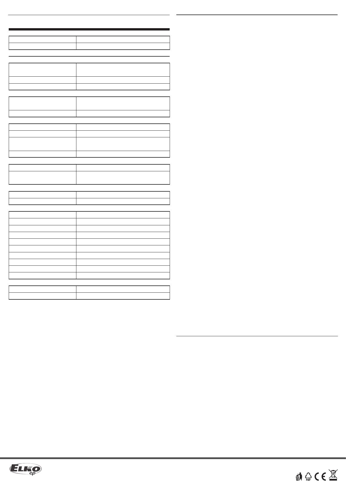
Technical parameters
Indication LED STATUS
Green LED RUN:
Red LED ERR:
Communication
iNELS BUS
Indication (LED BUS):
Maximum number of units:
Maximum cable length:
BUS EBM
Indication:
Maximum cable length:
Ethernet
Connector:
Communication speed:
Indication of the Ethernet
(LED ETH):
The default IP address:
Button RESET
Restart:
Reset (Factory Reset):
Power supply
Supply voltage/tolerance:
Rated current:
Operating conditions
Operating temperature:
Storage temperature:
Humidity:
Protection degree:
Overvoltage category:
Pollution degree:
Operating position:
Installation:
Design:
Terminal:
Dimensions and weight
Dimensions:
Weight:
Flashing - communication with BUS, ON - no communication
Flashing - no project, ON - unit STOP
green - unit status indication
red - BUS fault indication
max. 32 units to one BUS line
max. 300 m (depends on power loss)
green - indication communication
red - fault indication
max. 300 m
RJ45
100 Mbps
green - Ethernet communication
yellow - Ethernet speed 100 Mbps
192.168.1.1
short press
press the button to apply power,
release the button 10s after power is applied
27 VDC, -20/+10 %
50 mA (at 27 V DC)
-20 .. +55 °C
-25 .. +70 °C
max. 80%
IP20 devices, IP40 with cover in the switchboard
II.
2
any
to the switching board on the EN60715 DIN rail
1-MODULE
max. 2.5 mm2
94 x 17.6 x 64 mm
72 g
Installation BUS:
• Two-wired BUS with an arbitrary topology (not only to be as closed ci cle).
• With its own modulated communications on the DC voltage supply.
• One line of BUS allows you to connect up max. 32 units of iNELS3. The current load
of one line is max. 1 A. When connecting units which draw greater than 1A, power
supply PS3-100 iNELS and BPS3-01M with max. 3 A sampling can be used.
• Maximum length of the BUS is approximately 300 m (depends on the voltage drop).
• Recommended cable:
- iNELS BUS Cable - Twisted pair of copper wires with size of AWG20 wire (diameter
of 0.8 mm, cross-section of 0.5 mm2).
System BUS EBM:
• Used to connect the CU3-07M central unit with MI3-02M external masters, GSM
communicator GSM3-01M or converter DALI/DMX EMDC-64M.
• EBM has strictly linear topology and wires are connected to terminals EBM+ and
EBM-, wires can not be interchanged.
• When installing the bus, it is necessary to observe all the requirements for installing
the EBM interface (see the installation manual of the iNELS system).
• Max. length of the line of BUS is 300 m.
• The BUS EBM has to be terminated at both ends resistor with a nominal resistance
of 120 Ω. This part adapted to be inserted between terminals is included into cen-
tral units packages and it is necessary to insert between terminals EBM+ and EBM-.
• Reccomended cabling:
- CAT5e UTP and higher, or FTP CAT5e and higher or STP CAT5e and higher.
• The con gurations of units and the whole system are done via
Ethernet, through con guration software - iNELS3 Designer & Manager (iDM3),
which is designed for operating systems Windows 7, Windows 8 and Windows 10.
• The central unit features two communication protocols:
- ELKONET - to communicate with Connection Server or directly with the applica-
tion iHC.
• Supported Software:
- Parameterization, con guration, control and visualization: iNELS3 Designer &
Manager (iDM3).
• By means of iDM3, you can update rmware of central units and peripheral units
connected by BUS.


