Page is loading ...

COMMUNICATIONS SETUP
DBS STARTER PANEL
Version 1.0x
S90-450 CS/APR 2001
File: SERVICE MANUAL - SECTION 90
Replaces: NOTHING (New Manual)
Dist: 3, 3a, 3b, 3c

S90-450 CS DBS STARTER PANEL
Page 2 COMMUNICATIONS SETUP
Table of Contents
Communications Wiring Setup ______________________________________________________________ 3
Control Setup - Motor Control Setpoints - “Ram Dbs Motor Starter" Screen ____________________4
Ram Dbs Pictorial _________________________________________________________________________ 5
Warning
The Quantum has the capability of being modified by the user/owner in order to obtain different
performance characteristics. Any modification to the standard default settings may have a severe
negative impact on the operation and performance of the equipment. Any modification to these control
settings is the sole responsibility of the user/owner and Frick disclaims any liability for the consequences
of these modifications. It is possible that the modification of these settings may cause improper
operation and performance that results in property damage, personal injury or death. It is the
responsibility of the user/owner to evaluate and assess the consequences of their actions prior to
modifying the controls for this unit.

DBS STARTER PANEL S90-450 CS
COMMUNICATIONS SETUP PAGE 3
COMMUNICATIONS WIRING SETUP
1. Ensure that both the Quantum and DBS are
powered OFF.
2. Configure the DBS Dip Swicth (SW4). See
pictorial drawing 1 for location of this switch:
· Switch position 1 set to the right
· Switch position 2 set to the left
· Switch position 3 set to the left
· Switch position 4 - 8 are customer
configured and have no effect on
communications
3. Using the “RAM DBS PICTORIAL” drawing on
page 5, route the communications cable (Frick
P/N 640D0116H42) between the Quantum
Control and DBS Starter board. When running
this cable, ensure that the following information is
obeyed:
· Route the cable so that the end with three
wires starts at the Quantum end, and the
end with two wires is directed towards the
DBS.
· The communications cable is recommended
to be run within its own separate conduit.
· Keep the Communications cable away from
any high voltage wiring.
· Do not run the communications parallel to
any AC wiring.
4. Locate Analog Board 1. All of the Digital and
Analog boards have white 16 pin connectors on
them. The digital boards end of the board), the
Analog boards have just one connector. Look at
P9 of the Analog board (s) and determine which
of them has only one row of blue wires attached
to this plug, this will be connector P11, and is
where the wiring of the following steps will be
inserted into.
5. The Red wire of the cable will attach to terminal
position #1 (TR+) of the DBS, the other end will
attach to position #6 (+) of the plug (P11) which is inserted
into P9 on the Analog 1 Board.
6. The Black wire of the cable will attach to terminal position
#2 (TR-) of the DBS, the other end will attach to position
#5 (-) of the plug (P11) which is inserted into P9 on the
Analog 1 Board.
7. If the overall length of this cable is not sufficent to reach
between the Quantum and the DBS, it will be necessary to
splice the additional length in. If a splice is required,
ensure that it is mechanically as well as electrically
correct, and that it meets all local and national electrical
codes.
8. Refer to the “RAM DBS PICTORIAL” at the end of this
document for further infromation.
9. Power ON the DBS and then the Quantum.
10. You will now need to set the Quantum up to recognize the
DBS Starter. When the Quantum “HOME” Display
appears:
· Press the [MENU] screen key.
· Press the [FACTORY SETUP] key.
· Enable the RAM DBS Motor Starter on “Factory
Setup” screen.
· Press the [MENU] key.
· Press the [CONTROL SETUP] key.
· Press the [MOTOR SETPOINTS] key.
· Enter motor nameplate data (Motor Amps, Volts,
Horsepower, etc.). When completed, press [OK].
· Press the [DBS MOTOR STARTER] key.
· Verify communications between the Quantum and the
DBS starter. This can be done by locating the “DBS
Software Version” on the display. The value next to
the version should show “2.50” or higher. A value of
“0.00” indicates a communications failure, and you
will need to troubleshoot. If the value shown is
correct, proceed to the next step.
11. Refer to page 4 (CONTROL SETUP - MOTOR CONTROL
SETPOINTS “RAM DBS MOTOR STARTER" DISPLAY)
to set up the Quantum to control the DBS.

S90-450 CS DBS STARTER PANEL
Page 4 COMMUNICATIONS SETUP
CONTROL SETUP -
MOTOR CONTROL SETPOINTS -
“RAM DBS MOTOR STARTER" SCREEN
This screen is available if a RAM DBS motor starter has
been setup for use with the Quantum. The DBS
accelerates the motor in a smooth stepless motion,
therefore it reduces supply voltage dip during motor start
and mechanical shock on the compressor. Reference the
DBS Operator’s Guide and Instruction Manual or Contact
RAM Industries Inc. in Leesport, Pennsylvania at 800-220-
8697 with any further questions concerning the setup and
operation of the RAM DBS.
The current system conditions of the RAM DBS are
displayed for monitoring. The “Time Till Start” value will
also be displayed on both the “Motor Control” screen and
this screen. This value and the current recycle delay timer
must be zero prior to allowing the compressor to restart.
These timers are intended to prevent damage to the motor
from successive restarts. Both timers can be cleared by
pressing the [Clear Remaining Delay] key on the
“MotorControl” display. The “Time Till Start” is read from
the RAM DBS.
The following RAM DBS setpoints are modifiable from this
screen:
· Locked Rotor Current
· Stall Time
· Jam Current Level
· Jam Run Delay
· Service Factor
· Current Unbalance Alarm Level
· Current Unbalance Alarm Delay
· RTD Temperature Alarm Level
· RTD Temperature Alarm Delay
Alarms and trips (shutdowns) that are recorded by the
DBS are shown on the “RAM DBS Motor Starter” display
but must be cleared from the “Alarms / Shutdowns”
screen.
The following special selection is on this screen:
· Fault History - This selection displays the “RAM
DBS Motor Starter” screen with the fault history
of the RAM DBS system

DBS STARTER PANEL S90-450 CS
COMMUNICATIONS SETUP PAGE 5
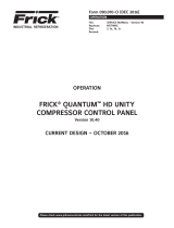
RAM DBS PICTORIAL
P11
DBS
READY
RUN
ALARM
TRIP
RESET
FLA
CURRENT
STEP
RAMP/BYP.
TIME
CONFIG.
SWITCHES
ON OFF
RAM
TB2
1 2 3
COMMUNICATIONS WIRING FROM DBS TO QUANTUM
WHT OR RED
BLK 6
7
8
ANALOG BOARD
1
4
TR-
TR+
5
7
3
1 1
2 2
4
#8760 BELDEN OR EQUAL 8
NETWORK
PORT IN DBS
STARTER
1
2
3
TR+
TR-
GND
COMMUNICATIONS WIRING SHALL BE
SEPARATE FROM ALL AC WIRING
4

S90-450 CS DBS STARTER PANEL
Page 6 COMMUNICATIONS SETUP
YORK Refrigeration
100 CV Avenue, P.O. Box 997 Waynesboro, Pennsylvania USA 17268-0997
Phone: 717-762-2121 · Fax: 717-762-8624 www.frickcold.com
Subject To Change Without Notice
Printed in U.S.A.
·
/