Page 4 17430-D01
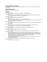
AMP002 Strain Gauge Pre-Amp
Fig. 1.1 AMP002 Circuit Diagram
1.4 Strain Gauge Bridge Connections
The Thorlabs piezo actuator with feedback (PZS001) is fitted with a full Wheatstone bridge strain gauge that can be monitored by
this circuitry.
See Fig. 1.2 for connection details, where necessary:
Fig. 1.2 Bridge Connections
Caution
When used with the BPC series controllers, connections to the bridge amplifier circuit are as detailed in Fig. 1.1 above.
When used with the KSG101 K-Cube Reader, the TP2 and TP3 connections must be swapped as follows:
TP1 (Red) Oscillator output to strain gauge bridge
TP2 (Blue) Positive input for differential amplifier
TP3 (Yellow) Negative input for differential amplifier
TP4 (Black) Ground
Caution
For correct operation, the value of the ID resistor (R6) must be chosen to match the travel of the piezo stack being driven
- see Table 1 in Fig. 1.1 above.
Use a standard 1% 0.25W resistor.
0VA
0VA
+15V
0VA
0VA
-15V
0VA
0VA
0VA
0VA
0VA
0VA
0VA
+15V
-15V
+15V
-15V
+15V
-15V
0VA
0VA
0VA
0VA
ID RESISTOR
BLACK
GAIN
RED
TP1
OSC
REF
V-
V+
_
+
U1
INA128UA
6
2
3
1
8
5
7
4
C6
10uF
25V X5R
C3
100n
R6
Refer to Table 1
-
+
U2A
TLE2072
2
3
1
4
8
C9
22pF
YELLOW
TP2
IN-
GREEN
TP7
MON
R8 3K3
D9M
J1
1
2
3
4
5
6
7
8
9
OFFSET
VR2
10K
VR1
1K
C7
22pF
TP6
ID_RES2
C1 10uF
25V X5R
C2 10uF
25V X5R
TP8
GND
R2
47R
R3
270R
BLUE
TP3
IN+
C8
220pF
TP5
ID_RES1
-
+
U2B
TLE2072
6
5
7
R10
1K
BLACK
TP4
GND R7 10K
R5
47R
R1
47R
R4
10K
C4
100n
0VA 0VA 0VA 0VA
O3
MOUNTING HOLE
1
O2
MOUNTING HOLE
1
O1
MOUNTING HOLE
1
O4
MOUNTING HOLE
1
R9 1K
C5
10uF
25V X5R
Table 1 - ID Resistor Values
for Thorlabs Piezo Stacks
Value ±1% Max Displacement
0 20μm
1.1k 10μm
2.0k 30μm
3.0k 40μm
4.3k 50μm
6.2k 60μm
8.2k 200μm
10k 80μm
13k 15μm
18k 100μm
Vo
R4
R2 (dummy) R1 (active)
R3
(dummy)
VEX
Bridge Excitation Voltage
Blue (+ve)
Yellow (-ve)
Red (+ve) Black (-ve)
(active)
V0 = Output voltage of full bridge
VEX = Excitation voltage


