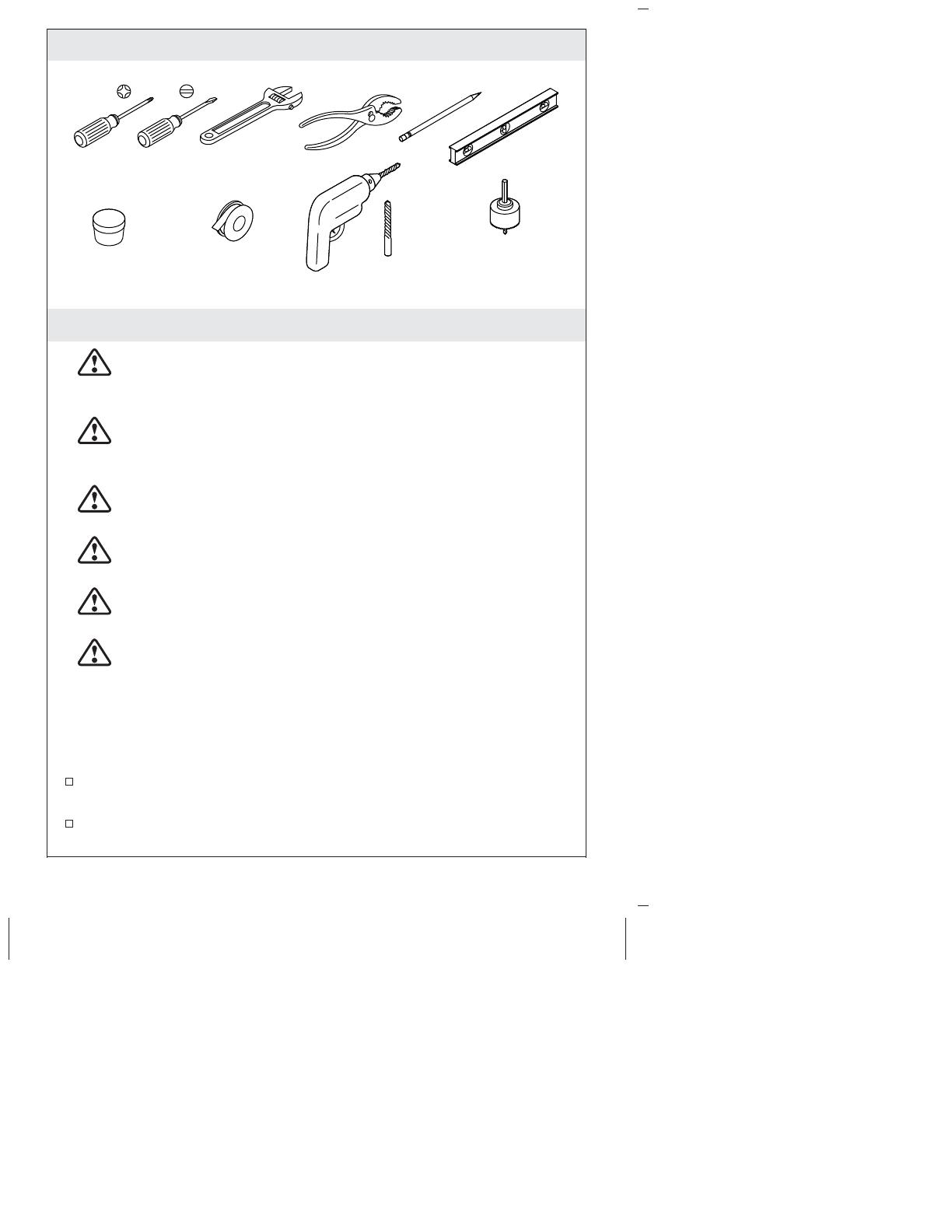
Kohler 103K36-SANA-CP Installation guide

Category
Sanitary ware
Type
Installation guide
Tools and Materials
Before You Begin
WARNING: Risk of fresh water contamination. This faucet
contains back-siphonage protection. Do not remove any
internal components.
WARNING: When using electrical products, basic
precautions should always be followed, including the
following:
DANGER: Risk of electric shock. Connect only to a circuit
protected by a Ground-Fault Circuit-Interrupter (GFCI)*.
WARNING: Risk of electric shock. Grounding is required. A
qualified electrician should make all electrical connections.
WARNING: Risk of electric shock. Disconnect power before
servicing.
WARNING: Risk of injury or property damage. Please read
all instructions thoroughly before beginning installation.
CAUTION: Risk of product damage. This product contains
sensitive electronic components. Do not store open containers of
chemical or cleaning products near this product. Cleaning rags or
sponges must be rinsed with fresh water before storage.
Provide a constant unswitched 120 VAC electrical outlet located
below the sink within 5’ (1.5 m) of the control box.
*Outside North America, this device may be known as a Residual
Current Device (RCD).
1-1/4" to 1-1/2"
Hole Bit1/8"
Sealant TapePlumbers Putty
1377340-2-A 2 Kohler Co.
Before You Begin (cont.)
Observe all local plumbing and building codes.
Shut off the water supply.
This faucet is for a single-hole bathroom sink.
For new installations, install the faucet and drain to the sink
before installing the sink.
The faucet shown in this guide may differ from your actual
product. The installation steps still apply.
In order for this faucet to function properly, install the faucet so
the sensor points directly toward the user.
Kohler Co. 3 1377340-2-A
1. Faucet Installation
NOTE: Before drilling the mounting hole, use the following
dimensions for proper placement:
A 1-1/4 (32 mm) minimum to 1-1/2 (38 mm) maximum
diameter mounting hole is required.
A minimum distance of 1-3/4 (44 mm) is required between the
back of the spout and the wall to allow access to the screw.
A 1-1/8 (29 mm) maximum distance is required between the
sink bowl edge and the base of the spout.
Install the Faucet
Determine the mounting-hole location.
Drill a hole through the mounting surface according to the
surface manufacturer’s instructions.
Install the gasket and plate onto the spout.
Install the stud to the underside of the faucet.
Insert the spout with flexible hoses and stud through the
mounting hole.
Connect the power wire and the supply hose under the sink.
From under the sink, slide the rubber washer and metal washer
onto the stud.
Thread the nut onto the stud and wrench-tighten to secure the
faucet to the mounting surface.
Flexible Hoses
Nut
Bracket
Stud
Rubber
Washer
O-Ring
Spout
Sensor
1377340-2-A 4 Kohler Co.
2. Install the Control Box
NOTE: Verify that the hose will reach the supply stop by attaching
the flex hose to the control box inlet.
NOTE: Determine the proper mounting location according to the
Specification Sheet.
Verify that the sensor cable is below the countertop.
Unthread the control box screws to remove the cover.
Drill pilot holes.
Use the standard wall anchors (provided) depending on your
wall material.
Attach the control box to the wall with the arrow pointing
upward. Secure with the two screws (provided).
Inlet
Kohler Co. 5 1377340-2-A
3. Connect the Control Box
IMPORTANT! The control box cover has slots for the spout wires
to fit. Verify that the wires are not pinched when installing the
cover.
Connect the 3-pin sensor cable from the valve cover to the 3-pin
sensor cable from the spout (red, white, and green cables).
Connect the solenoid cable from the valve cover to the solenoid
cable from the valve box (red and green cables).
Connect the 2-pin sensor cable from the valve cover to the 2-pin
sensor cable from the spout (orange and black cables).
Loosely secure the cover to the control box for future access.
Valve
Box
Valve
Cover
Power
Cable
Solenoid
Cable
3-Pin
Sensor
Cable
Power
Cable
Solenoid
Cable
3-Pin
Sensor
Cable
2-Pin
Sensor
Cable
2-Pin
Sensor
Cable
Spout
Wires
1377340-2-A 6 Kohler Co.
4. Supply Connections
Inlet Connections
Connect the flex hose from the control box to the supply stop.
Outlet Connections
Verify that the tube from the spout is the appropriate length to
reach the control box. Cut the tube if necessary. Remove any
burrs and sharp edges.
Insert the tube into the fitting (control box outlet end) until the
tube stops.
Verify that the tube is secure.
Outlet
Inlet
Flex Hose
Tube
From Spout
Supply
Stop
Flex Hose
Kohler Co. 7 1377340-2-A
5. Mixing Valve - If Included
If a mixing valve is included with your product, connect the
water outlet hose to the control box outlet.
Attach the supply hose to the control box inlet and outlet of
mixing valve.
Use a 3/8” compression connection (provided) to attach the cold
supply to the mixing valve cold inlet end (marked cold on the
adjustment plate).
Use a 3/8” compression connection (provided) to attach the hot
supply to the mixing valve hot inlet end (marked hot on the
adjustment plate).
Loosen the lock screw and adjust the temperature by rotating the
adjustment plate.
Retighten the lock screw.
Outlet
Hot Cold
Adjustment plate to
set water temperature.
Lock Screw
1377340-2-A 8 Kohler Co.
6. Install the AC Single Supply
IMPORTANT! Verify that you are following the correct power
system installation based on your model number. For a multi-output
AC supply power unit installation, refer to Install AC Multi-Output
Supply. For a hard wire power installation, refer to Hard Wire
Installation.
Unthread the control box screws to remove the control box cover.
Connect the power cords.
Plug the AC supply into the wall outlet.
Secure the excess wire under the counter.
Secure the control box cover to the control box.
IMPORTANT! The area in front of the sensor must be free of
objects during the 2 minute learning cycle or the faucet may not
function properly.
Allow 2 minutes for the sensor to cycle through the automatic
sensing distance.
Power
Cord
AC Supply
Kohler Co. 9 1377340-2-A
7. Install AC Multi-Output Supply
Mount the AC supply under the counter using two screws
(provided). Orient as shown.
Remove the cover.
Connect the faucet wire to the faucet.
If needed, cut and strip the AC supply wires to length.
Connect the stripped ends to the bottom terminal block in the
supply box.
Secure the terminal box cover to the terminal box.
NOTE: If a hard wired installation is required, refer to Hard Wire
Installation.
Plug the AC supply into the wall outlet.
Secure any excess wire under the counter.
IMPORTANT! The area in front of the sensor must be free of
objects during the 2 minute learning cycle or the faucet may not
function properly.
Allow 2 minutes for the sensor to cycle through the automatic
sensing distance.
AC
Supply
Red
Black
AC Gang
Supply
1377340-2-A 10 Kohler Co.
8. Hard Wire Installation
WARNING: Risk of electrical shock. Make sure the power
has been disconnected before performing the following
procedures.
Loosen the terminal block screws and remove the wires from the
top terminal block.
Loosen the outside nut of the strain relief and remove the power
cord.
Put the supply wires through the strain relief and connect to the
top terminal block.
NOTE: If a hard wired installation is required, the strain relief may
need to be replaced depending on wire used.
Tighten the nut on the strain relief.
Secure the terminal box cover to the terminal box.
Turn on the AC supply power.
Secure any extra wire under the counter.
IMPORTANT! The area in front of the sensor must be free of
objects during the 2 minute learning cycle or the faucet may not
function properly.
Allow 2 minutes for the sensor to cycle through the automatic
sensing distance.
Secure any excess
wire under counter.
Kohler Co. 11 1377340-2-A
9. Drain Installation
Disassemble the drain.
Apply plumbers putty to the underside of the flange and attach.
Apply thread sealant tape to the drain pipe threads. Tighten the
nut.
Connect the trapway. Wipe away excess plumbers putty.
Stainless
(Non-Staining)
Plumbers Putty
1377340-2-A 12 Kohler Co.
10. Installation Checkout
Using the key provided, remove the aerator from the spout.
If applicable, uncover the drain.
Turn on the water supply and check for leaks. Adjust as needed.
Allow the water to run through the spout for about 1 minute to
remove any debris. Check for leaks and adjust as needed.
Temporarily cover the sensor on the faucet or close the water
supplies.
Using the key provided, reinstall the aerator to the spout.
Uncover the sensors on the faucet or turn on the water supplies.
Troubleshooting
Symptoms Probable Causes Recommended Action
1. No water flow. A. No power supply
or wrong
connection.
A. Check the power supply
and connection.
B. Object in sensing
range.
B. Remove the object.
C. Sensor eyes are
dirty.
C. Wipe the sensor eyes
with a damp soft cloth.
Wipe dry with a dry soft
cloth.
Kohler Co. 13 1377340-2-A
Troubleshooting (cont.)
Symptoms Probable Causes Recommended Action
2. Low flow. A. Supply pressure
is low.
A. Check incoming water
pressure. Pressure should
be at least 20 psi (137 kPa).
B. Aerator is
plugged.
B. Remove the aerator and
clean it. For
calcium/mineral deposits,
soak the aerator plastic
insert in a 50:50 mixture of
vinegar and water. Soak
only the insert and no other
components.
3. Constant water
flow.
A. Solenoid is not
working.
A. Order and install a new
solenoid assembly.
4. Sporadic water
flow.
A. The faucet is
angled incorrectly to
deck or misaligned
with user area.
A. Verify that the faucet is
mounted according to the
installation directions.
Ensure that the faucet is
installed in a position that
is above the rim of the sink.
B. The wires are
pinched or
damaged.
B. Remove the spout and
verify that the wires are
tucked inside the spout
before reassembling.
5. Sensor flashes
once
approximately
every 2 seconds.
There is no water
flow.
A. The AC
Connection is not
installed correctly.
A. Reconnect the AC
transformer connection.
1377340-2-A 14 Kohler Co.
  • Page 1 1
  • Page 2 2
  • Page 3 3
  • Page 4 4
  • Page 5 5
  • Page 6 6
  • Page 7 7
  • Page 8 8
  • Page 9 9
  • Page 10 10
  • Page 11 11
  • Page 12 12
  • Page 13 13
  • Page 14 14
  • Page 15 15
  • Page 16 16
  • Page 17 17
  • Page 18 18
  • Page 19 19
  • Page 20 20
  • Page 21 21
  • Page 22 22
  • Page 23 23
  • Page 24 24
  • Page 25 25
  • Page 26 26
  • Page 27 27
  • Page 28 28
  • Page 29 29
  • Page 30 30
  • Page 31 31
  • Page 32 32
  • Page 33 33
  • Page 34 34
  • Page 35 35
  • Page 36 36
  • Page 37 37
  • Page 38 38
  • Page 39 39
  • Page 40 40
  • Page 41 41
  • Page 42 42
  • Page 43 43
  • Page 44 44
  • Page 45 45
  • Page 46 46
  • Page 47 47
  • Page 48 48

Kohler 103K36-SANA-CP Installation guide

Category
Sanitary ware
Type
Installation guide

Ask a question and I''ll find the answer in the document

Finding information in a document is now easier with AI