Page is loading ...

Chesterfield & Sheraton 5
Freestanding Stove Range
Installation Instructions
IMPORTANT
THE OUTER CASING, FRONT AND GLASS PANEL BECOME EXTREMELY HOT DURING OPERATION AND WILL RESULT IN
SERIOUS INJURY AND BURNS IF TOUCHED. IT IS THEREFORE RECOMMENDED THAT A FIREGUARD COMPLYING WITH BS
8423 (LATEST EDITION) IS USED IN THE PRESENCE OF YOUNG CHILDREN, THE ELDERLY OR INFIRM.
Do not attempt to burn rubbish in this appliance. Please read these Instructions carefully before installation or use.
Keep them in a safe place for future reference and when servicing the fire.
The commissioning sheet found on page 3 of these instructions should be completed by the Installer.
PM1939.1.03.2021

2
CONTENTS
Covering the following models:
Chesterfield Eco Range
Installation Instructions ......................................................4
Essential Information .................................................................... ..........4
Dimensions .............................................................................................7
Distance to Combustibles.......................................................................8
Pre-installation ......................................................................................11
Smoke Control Settings........................................................................17
Installation ............................................................................................19
Commissioning ............................................................................. ........23
Maintenance & Servicing ..................................................24
Servicing ...............................................................................................24
Legal Requirements ..................................................................... ........29
Information Requirement - Solid Fuel ......................................... ........31
Exploded Parts ............................................................................. ........32
Service Records ........................................................................... ........35
MODEL WOOD MULTI- FUEL
Chesterfield 5
705-332 705-562
Chesterfield 5 Wide
705-346 705-577
Sheraton 5
SH-5W-E SH-5M-E
Sheraton 5 Wide
SH-5WIDW SH-5WIDM-E

3
Dealer appliance was purchased from:
Name:
Address:
Telephone number:
Essential information - MUST be completed:
Date Installed:
Model Description:
Serial Number:
Installation Engineer:
Company Name:
Address:
Telephone number:
Commissioning Checks - to be completed and signed:
Is flue system correct for the appliance:
YES NO
Flue swept and soundness test complete:
YES NO
Smoke test completed on installed appliance YES NO
Spillage test completed YES NO
Use of appliance and operation of controls explained YES NO
Clearance to combustible materials checked YES NO
Instruction book handed to customer YES NO
CO Alarm Fitted YES NO
Flue draught Reading (Pa) HOT COLD
Signature: ............................................................................ Print Name: ..........................................................................
To assist us in any guarantee claim please complete the following information:-
APPLIANCE COMMISSIONING SHEET

4
ESSENTIAL INFORMATION - MULTI-FUEL STOVE
GENERAL
Model:
Chesterfield 5
Sheraton 5
Chesterfield 5 Wide
Sheraton 5 Wide
Nominal Heat Output
Wood kW 5.0 5.0 5.0 5.0
Solid Fuel kW 5.0 5.0 5.0 5.0
Efficiency
Wood % 79.5 79.5 76.5 76.5
Solid Fuel % 78.6 78.6 79.4 79.4
CO @ 13% O
2
Wood % 0.11 0.11 0.11 0.11
Solid Fuel % 0.04 0.04 0.08 0.08
Weight Kg 95 95 110 110
Recommended Fuels
Wood
Seasoned Wood (less than 20% moisture content)
Solid Fuel
Briquette smokeless fuel suitable for closed appliances
(Ancit-Phuracite-Maxibrite-Taybrite-Homefire Ovals)
As tested to the requirements of EN 13240 for intermittent operation
FLUES
Flue/Chimney Size
Without flue liner Round (Diameter)
mm ‡153 ‡153 ‡153 ‡153
inch 6 6 6 6
Without flue liner system (Square)
mm 135 135 135 135
inch 5½ 5½ 5½ 5½
With Liner of Factory made system
(diameter) installed in accordance with
manufacturers instructions
mm 150 150 150 150
inch 6 6 6 6
Flue/Chimney
minimum height**
All products
**must be 4.5m from the hearth to the top
of the flue, with no horizontal sections and
a maximum of 4 bends. Bends must have
angles of less than 45 degrees from the
vertical.
m 4.5 4.5 4.5 4.5
feet 15 15 15 15
Flue Draught
Min
Pa
10 10 10 10
Nominal 12 12 12 12
Max 20 20 20 20
Flue Gas Mass Flow
Wood g/s 3.8 3.8 5.9 5.9
Solid Fuel g/s 3.4 3.4 3.8 3.8
Average Flue Gas
Temperature
Wood
o
C 312 312 261 261
Solid Fuel
o
C 338 338 272 272
Flue Outlet Size
(Top or Rear Option)
All
mm 128 128 128 128
inch 5 5 5 5
European Min Spec for Chimney Flue - T400 N2 D 3 G50
VENTILATION
A) Traditionally Built Homes
• Where leakage is greater than 5m
3
/hour/m
2
.
• Ventilation normally required = 550mm
2
per kW output over 5kW
B) Modern Construction Homes
• Where leakage is less than 5m
3
/hour/m
2
.
• Ventilation normally required = 550mm
2
per kW
A Additional Ventilation
mm2 None None None None
cm2 None None None None
in2 None None None None
B Additional Ventilation
mm2 2750 2750
2750 2750
cm2 27.5 27.5 27.5 27.5
in2 4.4 4.4 4.4 4.4
For full technical details on ventilation see Technical Appendix on Page 22

5
ESSENTIAL INFORMATION - WOOD STOVE
GENERAL
Model:
Chesterfield 5
Sheraton 5
Chesterfield 5 Wide
Sheraton 5 Wide
Nominal Heat Output Wood kW 5.0 5.0 5.0 5.0
Efficiency Wood % 77.6 77.6 75.6 75.6
CO @ 13% O
2
Wood % 0.09 0.09 0.14 0.14
Weight Wood Kg 91.5 91.5 105.5 105.5
Recommended Fuels
Wood
Seasoned Wood (less than 20% moisture content)
As tested to the requirements of EN 13240 for intermittent operation
FLUES
Flue/Chimney Size
May be reduced to 128mm (5")
if burning approved smokeless
fuels or burning wood in an
appliance approved for use in
a DEFRA smoke control area
Without flue liner Round (Diameter)
mm 153 ‡153 153 ‡153
inch 6 6 6 6
Without flue liner system (Square)
mm 135 135 135 135
inch 5½ 5½ 5½ 5½
With Liner of Factory made system
(diameter)
installed in accordance with manufacturers
instructions
mm 150 150 150 150
inch 6 6 6 6
Flue/Chimney
minimum height**
All products
**must be 4.5m from the hearth to the top
of the flue, with no horizontal sections and
a maximum of 4 bends. Bends must have
angles of less than 45 degrees from the
vertical.
m 4.5 4.5 4.5 4.5
feet 15 15 15 15
Flue Draught
Min
Pa
10 10 10 10
Nominal 12 12 12 12
Max 20 20 20 20
Flue Gas Mass Flow Wood g/s 4.6 4.6 5.5 5.5
Average Flue Gas
Temperature
Wood
o
C 284 284 273 273
Flue Outlet Size
(Top or Rear Option)
All
mm 128 128 128 128
inch 5 5 5 5
European Min Spec for Chimney Flue - T400 N2 D 3 G50
VENTILATION
A) Traditionally Built Homes
• Where leakage is greater than 5m
3
/hour/m
2
.
• Ventilation normally required = 550mm
2
per kW output over 5kW
B) Modern Construction Homes
• Where leakage is less than 5m
3
/hour/m
2
.
• Ventilation normally required = 550mm
2
per kW
A Additional Ventilation
mm2 None None None None
cm2 None None None None
in2 None None None None
B Additional Ventilation
mm2 2750 2750 2750 2750
cm2 27.5 27.5 27.5 27.5
in2 4.4 4.4 4.4 4.4
For full technical details on ventilation see Technical Appendix on Page 22

6
Installation
Registered Professional:
Before installation and/or use of this appliance please read these instructions fully and carefully to ensure that you have fully understood their
requirements.
The appliance must be fitted by a registered installer, or approved by your local building control officer.
Structural Support:
If installing on a wooden floor check that the floor joists are strong enough to bear the weight of the insert, chimney and construction parts.
Hearth:
A Constructional Hearth with a depth of 125mm and a 12mm Decorative Hearth Plate must be installed to protect a combustible floor from the
risk of falling embers if mounted directly on the floor.
The Decorative Hearth must extend 300mm in front of the appliance and can be made of natural stone, concrete, metal or glass.
Final inspection of the installation:
When it has been installed, the appliance must be commissioned in accordance with standards and practices to ensure full working order and
a correct handover given to the customer.
Flue and Chimney
The flue or chimney system must be able to withstanding flue temperatures of up to 400
0
C.
The external diameter of the connection sleeve is 155mm.
In normal operating mode, draft in the chimney should be 20-25 Pa close to the connection sleeve. The draft is affected primarily by the length
and area of the chimney and also by how well sealed it is.
The minimum recommended chimney length is 3.5m and a suitable cross-section area is 150-200cm² (140-160 mm in diameter).
Sharp bends and horizontal lengths in a flue pipe reduce the draft in the chimney.
It must be possible to sweep the full length of the flue, and the soot doors must be easily accessible.
Carefully check that the chimney is sealed and that there is no leakage of smoke from the connections.
Combustion Air Supply
When the appliance is installed, it is essential to ensure adequate air is supplied to the room. Air can be provided indirectly via a vent in the
outer wall or via a duct from the outside that connects to the sleeve on the underside of the insert. The required volume of combustion air is
about 20 m3/hour.
The outer diameter of the combustion air connection sleeve is 65mm.
If a pipe is longer than 1 m, its diameter must be increased to 100mm and a larger wall vent will be required.
In heated spaces, the flue must be insulated to prevent condensation using 30mm mineral wool covered with a vapour barrier. The hole in the
wall (or floor) at the exit point must be properly sealed with flue jointing compound.
A a flexible pipe to provide external directly into the appliance is available and must be fitted at the time of installation.

7
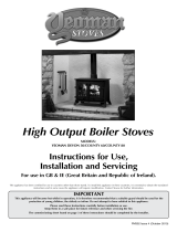
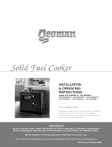
DIMENSIONS
All dimensions in mm (25.4 mm = 1”)
A
A1
(GLASS
VIEWING
AREA)
B
C D E
E1 (GLASS VIEWING AREA)
F
G
SHORT
LEG
LONG
LEG
WOOD MULTI-FUEL
SHORT
LEG
LONG
LEG
Chestereld 5 472 305 614 660 397 110 431 317 278 128 494 540
Chestereld 5 Wide 581 412 702 748 357 110 519 410 359 128 561 607
A
D
C*
E
B
F
A1
E1
G
CHESTERFIELD 5 & 5W
A
A1
(GLASS
VIEWING
AREA)
B
B1
(GLASS
VIEWING
AREA)
C D E F
G H
I J K
SHORT
LEG
LONG
LEG
SHORT
LEG
LONG
LEG
SHORT
LEG
LONG
LEG
SHERATON 5
472 305 614 660
Wood:
332
M/F:
279
359 613 615 634 493 539 136 182 150 135 121
SHERATON 5
WIDE
581 415 703 749
Wood:
410
M/F:
360
303 703 704 723 561 607 136 182 150 135 121
SHERATON 5 & 5W
F
A
J
I
B
A1
B1
H
K
G
D
E
C

8
CLEARANCE TO NON-COMBUSTIBLE MATERIAL
Rear Wall
Side Wall
B
A
A
PARALLEL POSITION CLEARANCES
No Combustible Wall in front of the appliance
CORNER POSITION CLEARANCES
B
A
A
Height above appliance
C
(Wall Height)
DISTANCE TO NON-COMBUSTIBLE MATERIALS
Distance of
Appliance to Wall (A)
Minimum Thickness
of wall (B)
Minimum Height of
Wall (C)
0mm - 50mm* 200mm Height of appliance +
300mm OR 1200mm
from the hearth (take
largest dimension)
51mm - 300mm 75mm
300mm+ No requirement No requirement
HEARTH THICKNESS
These appliances are suitable to stand on a 12mm decorative hearth.

9
CLEARANCE TO COMBUSTIBLE MATERIAL
A
B
D
C
C
OPEN SETTING
ENCLOSED SETTING
A
B
C
C
D D
A
E
DIMENSION A B C D
E
Fitted with Heat Shield Standard Clearance
Standard Model - Wood 1372 225 150 300 50 500
Standard Model - Multi-Fuel 1372 225 150 300 50 500
Wide Model - Wood 1381 225 150 250 50 500
Wide Model - Multi-Fuel 1381 225 150 250 50 500
DIMENSION A B C
D
Fitted
with Heat
Shield
Standard
Clearance
Standard Model - Wood 1072 225 300 50 500
Standard Model - Multi-Fuel 1072 225 300 50 500
Wide Model - Wood 1081 225 250 50 500
Wide Model - Multi-Fuel 1081 225 250 50 500

10
OPTIONAL EXTRAS
OUTSIDE AIR KIT
This appliance can be fitted with an optional kit to help bring
air directly into the appliance from outside. For installation and
operating procedures refer to the instructions supplied with the
Outside Air kit - Stovax Part No PM1654.
APPLIANCE PART NO.
Standard Model SH-5AIR
Wide Model SH-5WIDAIR
TWIN WALL HEAT SHIELD
(TWIN WALL INSTALLATIONS ONLY)
IF THE APPLIANCE IS TO BE INSTALLED IN
A COMBUSTIBLE SETTING THE MINIMUM
CLEARANCES CAN ONLY BE ACHIEVED USING A
TWIN WALL FLUE SYSTEM AND HEAT SHIELD.
Align the Heat Shield on the slots to cover the gap between the
Twin Wall and the Top Plate. The overlap must be at least 10mm.
Twin Wall Flue
Connector
Adapter
Heat
Shield
10mm
Minimum
10mm
Minimum
IMPORTANT
When installing the flue pipe, there must be no
exposed single wall flue, & a minimum 10mm
expansion gap must be left between the Twin Wall
flue & the top face of the Top Plate.

11
PRE-INSTALLATION
To make the installation of the appliance easier it is best to remove the internal components before installation.
OPENING THE DOOR
Chesterfield Shown
1
2
LOG GUARD - WOOD MODELS
1
2
3

12
LOG GUARD - MULTI-FUEL MODELS
1
2
3
BAFFLE
The appliance is fitted with a baffle in the top of the firebox to
maintain efficient combustion.
ALLOW THE STOVE TO COOL FULLY BEFORE
REMOVING THE BAFFLE SYSTEM.
STANDARD MODEL
WIDE MODEL

13
STANDARD MODEL
1
2
3
4
WIDE MODEL
1
2
3
4

14
BRICK PROTECTOR
- MULTI-FUEL ONLY
1
2
3
FIREBRICKS
1
2
3
4
5

15
3
REMOVAL OF THE MULTI-FUEL GRATE
(MULTI-FUEL MODELS ONLY)
1
2
6
WOODBURNING TRAY - WOOD ONLY
1
2

16
3
4
5
6
FITTING LONGER LEGS (OPTIONAL)
It is possible to swap the legs of the appliance for a longer
equivalent.
MODEL
PRODUCT CODE
(SET OF 4)
Sheraton 5 & 5W SHLEG170
Chesterfield 5 & 5W 705-807
1
2
3
NOTE: Ensure the legs are stable, and do not move,
wobble, or appear unsteady.

17
SMOKE CONTROL AREA SETTINGS
Mandatory for smoke control areas
MODIFICATION WILL NEED TO BE CARRIED OUT PRIOR TO INSTALLATION OF THE APPLIANCE.
WOOD BURNING MODELS
Woodburning appliances are supplied with a
pre-tted smoke control setting and has been
independently tested to PD6434 making them
exempt from the controls that generally apply in
Smoke Control Areas.
THE SMOKE CONTROL FACILITY IS SUPPLIED
DISABLED AND MUST THEREFORE BE MODIFIED
BEFORE INSTALLATION, IN ORDER FOR THE
APPLIANCE TO MEET THE REQUIREMENTS OF A
SMOKE CONTROL AREA AND MUST BE OPERATED
CORRECTLY IN ORDER TO MINIMISE THE AMOUNT
OF SMOKE PRODUCED.
If this appliance is installed outside of a Smoke
Control Area then the Smoke Control setting can
be left disabled to give more control over the lower
burn rates.
Any modifications to the setting should only be
done by a suitably qualified installer and must be
done at the time of installation.
1
B. ENABLED
A. DISABLED
2
MULTI-FUEL BURNING MODELS
Multi-fuel appliances are supplied with an additional
slide restrictor plate making them exempt from
the controls that generally apply in Smoke Control
Areas.
THIS PLATE IS SUPPLIED SEPARATELY AND
THE APPLIANCE MUST BE MODIFIED BEFORE
INSTALLATION, IN ORDER TO MEET THE
REQUIREMENTS OF A SMOKE CONTROL AREA
AND MUST BE OPERATED CORRECTLY IN ORDER
TO MINIMISE THE AMOUNT OF SMOKE PRODUCED.
If this appliance is installed outside of a Smoke Control
Area then there is no need to fit the supplied plate.
Any modifications to the setting should only be
done by a suitably qualified installer and must be
done at the time of installation.
APPLIANCE PRODUCT CODE
Sandard Model Multi-Fuel 705-562 / SH-5M-E
Wide Model Multi-Fuel 705-577 / SH-5WIDM-E
1
2

18
3
The Plate can now be replaced.
TWIN WALL HEAT SHIELD
(TWIN WALL INSTALLATIONS ONLY)
IF THE APPLIANCE IS TO BE INSTALLED IN
A COMBUSTIBLE SETTING THE MINIMUM
CLEARANCES CAN ONLY BE ACHIEVED USING A
TWIN WALL FLUE SYSTEM AND HEAT SHIELD.
1
Twin Wall Flue
Connector
Adapter
Heat
Shield
10mm
Minimum
10mm
Minimum
2
IMPORTANT
When installing the flue pipe, there must be no
exposed single wall flue & a minimum 10mm
expansion gap must be left between the Twin Wall
flue & the top face of the Flue Collar.

19
INSTALLING THE APPLIANCE
Take care when installing the appliance. Careless handling
and use of tools can damage the finish and/or area.
The appliance is factory set with the blanking plate fitted on the
rear outlet.
Blanking
Plate
Flue Collar Inner
Chestereld 5 shown
TOP FLUE INSTALLATION
CAST TOP PLATE
The cast top plate must be tted prior to connecting the ue.
Line up edges
of cast top
plate with the
appliance
1
Seal the connecting joints.
2
The Flue must be installed in accordance with
manufacturers instructions.
Flue pipe
Flue Collar
Seal collar
with re
cement
Chestereld 5 shown
3
A TYPICAL TOP FLUE PIPE INSTALLATION
Connection to chimney as
detailed in Building Regulations
135˚ Elbow with
access cover
Flue Pipe x
612 long
600mm minimum
1000mm max
unsupported
All Models
4

20
REAR FLUE INSTALLATION
The appliance is factory set with the blanking plate
fitted on the rear outlet.
The plate will need to be removed and fitted to the top
of the appliance prior to installation.
1
Knockout
Plate
Databadge
Twin Wall Shield
2
Fuel Seal
Flue Blanking Plate
3
4
5
6
7
/