
M
M
M
X
X
X
-
-
-
3
3
3
U
U
U
B
B
B
/
/
/
M
M
M
X
X
X
-
-
-
4
4
4
U
U
U
B
B
B
/
/
/
M
M
M
X
X
X
-
-
-
7
7
7
U
U
U
B
B
B
0
User Manual
Matrix Switcher
8x8 / 16x16 / 32x32
MX-3UB / MX-4UB / MX-7UB
V.2017MX-81632UB.00

M
M
M
X
X
X
-
-
-
3
3
3
U
U
U
B
B
B
/
/
/
M
M
M
X
X
X
-
-
-
4
4
4
U
U
U
B
B
B
/
/
/
M
M
M
X
X
X
-
-
-
7
7
7
U
U
U
B
B
B
1
COPYRIGHT AND TRADEMARKS
All rights reserved by AV LINK GROUP LTD. No part of this document may be
reproduced in any form or by any means without written permission from the product
manufacturer. Changes are periodically made to the information in this document.
They will be incorporated in subsequent editions. The product manufacturer may make
improvements and /or changes in the product described in this document at any time.
All the registered trademarks referred to this manual are belonging to their respective
companies.

M
M
M
X
X
X
-
-
-
3
3
3
U
U
U
B
B
B
/
/
/
M
M
M
X
X
X
-
-
-
4
4
4
U
U
U
B
B
B
/
/
/
M
M
M
X
X
X
-
-
-
7
7
7
U
U
U
B
B
B
2
BEFORE YOU BEGIN
Follow all instructions marked on the device during using.
Provide proper ventilation and air circulation and do not use near water.
It is better to keep it in a dry environment.
Place the device on a stable surface (example cart, stand, table, etc.).
The system should be installed indoor only. Install either on a sturdy rack or desk in a
well-ventilated place.
Make sure the rack is level and stable before extending a device from the rack if
necessary.
Make sure all equipments installed on the rack including power strips and other
electrical connectors are properly grounded.
Only use the power cord supported with the device.
Do not use liquid or aerosol cleaners to clean the device.
Always unplug the power to the device before cleaning.
Unplug the power cord during lightning or after a prolonged period of non-use to
avoid damage to the equipment.
Do not stand on any device while installing the device to the rack.
Do not attempt to maintain the device by yourself, any faults, please contact your
vendor.
Save this manual properly for future reference.

M
M
M
X
X
X
-
-
-
3
3
3
U
U
U
B
B
B
/
/
/
M
M
M
X
X
X
-
-
-
4
4
4
U
U
U
B
B
B
/
/
/
M
M
M
X
X
X
-
-
-
7
7
7
U
U
U
B
B
B
3
TABLE OF CONTENTS
Copyright and Trademarks .......................................................................................................... 1
Before You Begin .......................................................................................................................... 2
Table of Contents .......................................................................................................................... 3
Table of Figures ............................................................................................................................ 5
Chapter 1 Overview ...................................................................................................................... 7
1.1 Introduction ..................................................................................................................... 7
1.2 Packing ............................................................................................................................ 8
Chapter 2 Features ...................................................................................................................... 9
Chapter 3 Specifications ............................................................................................................ 10
Chapter 4 Installation ................................................................................................................. 11
Chapter 5 Panels ........................................................................................................................ 13
5.1 Front Panel .................................................................................................................... 13
5.2 Rear Panel .................................................................................................................... 16
Chapter 6 Connections .............................................................................................................. 19
6.1 Input/Output Connections ........................................................................................... 21
6.1.1 Input Connections ............................................................................................. 21
6.1.2 Output Connections.......................................................................................... 21
6.2 IR Pass-Through Connections ................................................................................... 22
6.3 Remote Control Connections ..................................................................................... 23
6.3.1 RS-232 ............................................................................................................... 23
6.3.2 RJ45 LAN Port .................................................................................................. 25
6.4 IR EXT Connection ...................................................................................................... 26
6.5 Power Connection........................................................................................................ 26
6.6 DIP Switcher ................................................................................................................. 27
Chapter 7 Remote Configurations ........................................................................................... 28
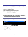
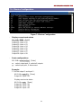
7.1 Telnet Commands ........................................................................................................ 28
7.1.1 Command List and Reboot ............................................................................. 28
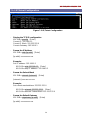
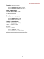
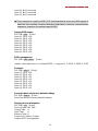
7.1.2 IP/Telnet Configuration .................................................................................... 29
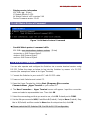
7.1.3 Device Configuration ........................................................................................ 31
7.1.4 AV Matrix Protocol Command ......................................................................... 34
7.2 RS-232 Commands ..................................................................................................... 34
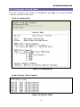
7.2.1 Commands List and Status ............................................................................. 35
7.2.2 HDMI Command ............................................................................................... 36
7.2.3 EDID Command ................................................................................................ 36
7.2.4 HDMI Output Resolution Commands ............................................................ 37
7.2.5 Restore Default Command ............................................................................. 37
Chapter 8 Operation Examples ................................................................................................ 38

M
M
M
X
X
X
-
-
-
3
3
3
U
U
U
B
B
B
/
/
/
M
M
M
X
X
X
-
-
-
4
4
4
U
U
U
B
B
B
/
/
/
M
M
M
X
X
X
-
-
-
7
7
7
U
U
U
B
B
B
4
Chapter 9 Troubleshooting ........................................................................................................ 49
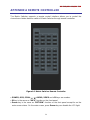
Appendix A Remote Controller ................................................................................................. 51
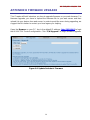
Appendix B Firmware Upgrade ................................................................................................ 52

M
M
M
X
X
X
-
-
-
3
3
3
U
U
U
B
B
B
/
/
/
M
M
M
X
X
X
-
-
-
4
4
4
U
U
U
B
B
B
/
/
/
M
M
M
X
X
X
-
-
-
7
7
7
U
U
U
B
B
B
5
TABLE OF FIGURES
Figure 1-1 MX-3UB ...................................................................................................................... 7
Figure 1-2 MX-4UB ...................................................................................................................... 7
Figure 1-3 MX-7UB ...................................................................................................................... 7
Figure 4-1 MX-3UB with 3U Rack-Mount ............................................................................... 11
Figure 4-2 MX-4UB with 4U Rack-Mount ............................................................................... 11
Figure 4-3 MX-7UB with 7U Rack-Mount ............................................................................... 12
Figure 4-4 Mount the Device in the Rack ............................................................................... 12
Figure 5-1 MX-3UB Front Panel (8 I/O Keys) ........................................................................ 13
Figure 5-2 MX-4UB Front Panel (16 I/O Keys) ...................................................................... 13
Figure 5-3 MX-7UB Front Panel (32 I/O Keys) ...................................................................... 14
Figure 5-4 MX-3UB Rear Panel (8 I/O Jacks)........................................................................ 16
Figure 5-5 MX-4UB Rear Panel (16 I/O Jacks) ..................................................................... 16
Figure 5-6 MX-7UB Rear Panel (32 I/O Jacks) ..................................................................... 17
Figure 5-7 IR Blaster Pin Definitions ....................................................................................... 18
Figure 5-8 IR Receiver Pin Definitions .................................................................................... 18
Figure 6-1 MX Series Connections .......................................................................................... 19
Figure 6-2 Modules Deployment .............................................................................................. 20
Figure 6-3 Input Connections ................................................................................................... 21
Figure 6-4 Output Connections ................................................................................................ 21
Figure 6-5 IR Pass-Through Connections .............................................................................. 22
Figure 6-6 RS-232 and Control PC Connection .................................................................... 23
Figure 6-7a RS-232 – From Female DB9 (PC) to Male DB9 (Matrix) ............................... 24
Figure 6-7b RS-232 – From Female DB9 (PC) to Male DB9 (Matrix) ............................... 24
Figure 6-8 RS-232 – From Female DB25 (PC) to Male DB9 (Matrix) ............................... 24
Figure 6-9 LAN Port Connection .............................................................................................. 25
Figure 6-10 RJ45 Connector .................................................................................................... 25
Figure 6-11 IR EXT Connection ............................................................................................... 26
Figure 6-12 Power Connection ................................................................................................. 26
Figure 6-13 DIP Switcher .......................................................................................................... 27
Figure 7-1 Help Command ........................................................................................................ 28
Figure 7-2 IP/Telnet Configuration ........................................................................................... 29
Figure 7-3 Device Configuration .............................................................................................. 31
Figure 7-4 AV Matrix Protocol Command ............................................................................... 34
Figure 7-5 Command List .......................................................................................................... 35
Figure 7-6 Switcher Status ........................................................................................................ 35
Figure 7-7 HDMI Output Setup Command ............................................................................. 36
Figure 7-8 HDMI Output Setup Command - Example .......................................................... 36

M
M
M
X
X
X
-
-
-
3
3
3
U
U
U
B
B
B
/
/
/
M
M
M
X
X
X
-
-
-
4
4
4
U
U
U
B
B
B
/
/
/
M
M
M
X
X
X
-
-
-
7
7
7
U
U
U
B
B
B
6
Figure 7-9 EDID Setup Command ........................................................................................... 36
Figure 7-10 EDID Setup Command - Example...................................................................... 36
Figure 7-11 HDMI Output Resolution Setup Command ....................................................... 37
Figure 7-12 Resolution Setup Command - Example ............................................................ 37
Figure 7-13 Restore Default Command .................................................................................. 37
Figure A-1 Matrix Switcher Remote Controller ...................................................................... 51
Figure B-1 Update Switcher’s Firmware ................................................................................. 52

M
M
M
X
X
X
-
-
-
3
3
3
U
U
U
B
B
B
/
/
/
M
M
M
X
X
X
-
-
-
4
4
4
U
U
U
B
B
B
/
/
/
M
M
M
X
X
X
-
-
-
7
7
7
U
U
U
B
B
B
7
CHAPTER 1 OVERVIEW
1.1 Introduction
MX-Series is a new generation of Matrix Switcher equipped with HDMI high performance
video and audio switching equipment. It applies the bright keypad on the front panel
allowing you to detect the I/O status. Through 8, 16 or 32 sets separated HDMI sources,
you can transmit multimedia input separately to each multi-output equipment, thereby
minimizing signal attenuation and ensuring high definition, integrating high fidelity
graphics and audio signal output.
MX-Series is used mainly in TV broadcasting projects, multimedia conference halls, and
large display performances, TV teaching and command control centers. It boasts
features of power interruption protection during power surge, LCD display and
synchronous and integrate audio/visual switching functions. Matrix Switcher supports
HDMI Type A for both input and output connectors. Beside it also supports a RS-232 or
LAN communication port enables convenient communication with remote control
equipment to switch the multimedia signals.
Figure 1-1 MX-3UB
Figure 1-2 MX-4UB
Figure 1-3 MX-7UB

M
M
M
X
X
X
-
-
-
3
3
3
U
U
U
B
B
B
/
/
/
M
M
M
X
X
X
-
-
-
4
4
4
U
U
U
B
B
B
/
/
/
M
M
M
X
X
X
-
-
-
7
7
7
U
U
U
B
B
B
8
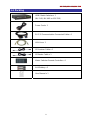
1.2 Packing
HDMI Matrix Switcher x 1
(MX-3UB, MX-4UB or MX-7UB)
Power Cord x 1
RS-232 Communication Connected Cable x 1
LAN Line x 1
IR Receiver Cable x 1
IR Blaster Cable x 1
Matrix Switcher Remote Controller x 1
AAA Battery x 2
User Manual x 1

M
M
M
X
X
X
-
-
-
3
3
3
U
U
U
B
B
B
/
/
/
M
M
M
X
X
X
-
-
-
4
4
4
U
U
U
B
B
B
/
/
/
M
M
M
X
X
X
-
-
-
7
7
7
U
U
U
B
B
B
9
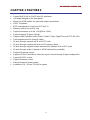
CHAPTER 2 FEATURES
Support 8x8,16x16 or 32x32 fixed I/O interfaces
Use bright keypad on the front panel
Mixed use HDMI cables for input and output connections
HDCP Compliant
EDID management (Copy from OUT port 1)
Memory control can up to 8 sets
Support resolution up to 4K x 2K@60Hz (8-bit)
Support original 3D pass through
Support High Definition Audio (Dolby TrueHD, Dolby Digital Plus and DTS-HD MA)
Fast response time for channel switch
IR pass-through supports all IN and OUT ports
IR pass-through supports all kinds of IR frequency band
IR pass-through supports duplex transmission between IN and OUT ports
IR pass-through switch is based on HDMI switched by controller
Support IR remote control
Support IR Mini-Controller to select the input channel through Output configuration
Support RS-232 control
Support Ethernet control
Internal universal power supply
Available in 3U, 4U and 7U rack for option

M
M
M
X
X
X
-
-
-
3
3
3
U
U
U
B
B
B
/
/
/
M
M
M
X
X
X
-
-
-
4
4
4
U
U
U
B
B
B
/
/
/
M
M
M
X
X
X
-
-
-
7
7
7
U
U
U
B
B
B
10
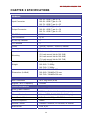
CHAPTER 3 SPECIFICATIONS
Hardware
Input Connector
MX-3U: HDMI Type A x 8
MX-4U: HDMI Type A x 16
MX-7U: HDMI Type A x 32
Output Connector
MX-3U: HDMI Type A x 8
MX-4U: HDMI Type A x 16
MX-7U: HDMI Type A x 32
RS-232 Connector DB9 Female
LAN Connector RJ45
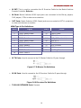
8 Pins Dip Switcher 1
LCD Module
1
Power 100VAC~240VAC, 50/60Hz, internal
Housing Black Aluminum
Mounting
Rack mountable
(3U-rack-mount kits for MX-3UB)
(4U-rack-mount kits for MX-4UB)
(7U-rack-mount kits for MX-7UB)
Weight
MX-3UB: 8.64Kg
MX-4UB: 11.90Kg
MX-7UB: 17.66Kg
Dimensions (LxWxH)
MX-3UB: 336x482x130 mm
MX-4UB: 336x482x176 mm
MX-7UB: 336x482x309 mm
Multimedia
Max. Resolution 4K x 2K@60Hz (8-bit)
Highest TMDS Frequency 600MHz
Control Information
HDMI Cable Distance
At least 10 meter
Baud Rate
9600 bps; 8 data bits, 1 stop bit, no parity
Ethernet Protocol
Telnet, HTTP, DHCP, TCP/IP, ICMP (ping)
Serial Control Port
9 Pin Female D Type RS-232 Connector
Control Sequence
Matrix
Remote Control
Remote Controller, IR Receiver, IR Blaster
Web Server
LAN, RJ45

M
M
M
X
X
X
-
-
-
3
3
3
U
U
U
B
B
B
/
/
/
M
M
M
X
X
X
-
-
-
4
4
4
U
U
U
B
B
B
/
/
/
M
M
M
X
X
X
-
-
-
7
7
7
U
U
U
B
B
B
11
CHAPTER 4 INSTALLATION
The Matrix Switcher has a black metallic housing. It can be placed on a sturdy desk
directly or installed on a 19-in bracket. You can also use the rubber feet pasted on the
bottom of the chassis to protect your device when you want to place the device on a
working desk.
Figure 4-1 MX-3UB with 3U Rack-Mount
Figure 4-2 MX-4UB with 4U Rack-Mount

M
M
M
X
X
X
-
-
-
3
3
3
U
U
U
B
B
B
/
/
/
M
M
M
X
X
X
-
-
-
4
4
4
U
U
U
B
B
B
/
/
/
M
M
M
X
X
X
-
-
-
7
7
7
U
U
U
B
B
B
12
Figure 4-3 MX-7UB with 7U Rack-Mount
Use the screws provided with the rack and a screw driver to firmly tighten the device in
the rack to prevent working lose due to vibration on the rack.
Figure 4-4 Mount the Device in the Rack

M
M
M
X
X
X
-
-
-
3
3
3
U
U
U
B
B
B
/
/
/
M
M
M
X
X
X
-
-
-
4
4
4
U
U
U
B
B
B
/
/
/
M
M
M
X
X
X
-
-
-
7
7
7
U
U
U
B
B
B
13
CHAPTER 5 PANELS
5.1 Front Panel
MX-3UB supports up to 8 Output/Input switching keys on the Front Panel allowing you to
switch signal quickly. Also refer to Chapter 8 Operation Examples.
Figure 5-1 MX-3UB Front Panel (8 I/O Keys)
MX-4UB supports up to 16 Output/Input switching keys on the Front Panel allowing you
to switch signal quickly.
Figure 5-2 MX-4UB Front Panel (16 I/O Keys)

M
M
M
X
X
X
-
-
-
3
3
3
U
U
U
B
B
B
/
/
/
M
M
M
X
X
X
-
-
-
4
4
4
U
U
U
B
B
B
/
/
/
M
M
M
X
X
X
-
-
-
7
7
7
U
U
U
B
B
B
14
MX-7UB supports up to 32 Output/Input switching keys on the Front Panel allowing you
to switch signal quickly.
Figure 5-3 MX-7UB Front Panel (32 I/O Keys)
OUT keys (output channel): Specify the Channel for HDMI signal output. These keys
configure the status or access the settings; you can also use these keys to switch
output channels.
IN keys (input channel): Specify the Channel for HDMI signal input. Use these keys
to switch the connected input channels or use them to instead of number keys upon
memory selections.
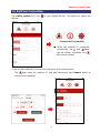
ALL: This key allows user to set single input channel to all output channels. The
usage of “ALL” key is the same as output key.
- Press the “ALL” key.
- Select the one of the IN keys.
- The selected IN x key will transfer the input signal to all output channels.
- You can also press the “ALL” key and then press the “OFF” key to disable all
the displayed switching settings.

M
M
M
X
X
X
-
-
-
3
3
3
U
U
U
B
B
B
/
/
/
M
M
M
X
X
X
-
-
-
4
4
4
U
U
U
B
B
B
/
/
/
M
M
M
X
X
X
-
-
-
7
7
7
U
U
U
B
B
B
15
OFF: Disable the entire output channels. Press one of the OUT x keys that want to
be disabled for the output channel, then press the “OFF” key. Likewise, press the
“ALL” key and then press the “OFF” key to disable all the displayed switching
settings. In addition to switching port menu, press “OFF” key can return to the main
screen during implementing in other menu.
EDID: 720P/FHD/4K60/4K30 (fix mode) and OUT1 (access the first output channel)
selection key.
- 720P Mode: The Matrix Switcher supplies a set of fixed EDID values to support
720P high performance TV.
- FHD Mode: The Matrix Switcher supplies a set of fixed EDID values to support
FHD(1080P/8bit) high performance TV.
- 4K60 Mode: The Matrix Switcher supplies a set of fixed EDID values to support
4K60 high performance TV.
- 4K30 Mode: The Matrix Switcher supplies a set of fixed EDID values to support
4K30 high performance TV.
- OUT1 Mode: The Matrix Switcher will access the EDID values of high
performance TV that connected to the first output channel, and copy the EDID
value to all the input channels so that the DVD player can support correct
resolution to all the HDTV.
RETURN: Press this key to go back to main screen.
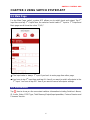
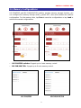
PLUG: Press this key to show you the status of all HDMI IN/OUT Type A jacks on the
rear panel. If the HDMI IN/OUT jack is connected, it will appear “O” on the screen.
Alternatively, it will appear “X” specified the HDMI IN/OUT jack is unused.
INFO: This key can show you the ID, IP address and In/Out port information.
Press PLUG and INFO keys simultaneously to show you the firmware versions of
modules.
STO: The “Store Key” saves all current output/input corresponding relations up to 8
sets for a memory control.
- Press the “STO” key firstly.
- Arrange memory location. (Support up to 8 sets of memories, user can select
the memory location through OUT1~OUT8/IN1~IN8.)
- The relations among all settings will be saved in the memory permanently.
RCL: The “Retriever Key” retrieves all settings that are saved in the memory.
- Press the “RCL” key firstly.
- Then make a random to select one of output/input channel key 1~8.
- The system will retrieve the saved all status and implement current status
switching if the previously saving channel is selected.

M
M
M
X
X
X
-
-
-
3
3
3
U
U
U
B
B
B
/
/
/
M
M
M
X
X
X
-
-
-
4
4
4
U
U
U
B
B
B
/
/
/
M
M
M
X
X
X
-
-
-
7
7
7
U
U
U
B
B
B
16
Press and hold STO and RCL keys simultaneously at least 1 sec. to restore to factory
default values.
ACTIVE LED: A clear LED indicator designed for reaction by pressing keys on the
front panel and remote controller. Refer to Appendix A Remote Controller.
IR Receiver: Infrared receiver can receive signals from the Matrix Switcher Remote
Controller.
LCD: LCD display shows current Matrix Switcher status and operation status.
Press any keys on the front panel or controller to enable the light of LCD momentarily.
This feature cannot be controlled by RS-232 or LAN.
5.2 Rear Panel
MX-3UB/4UB/7UB supports up to 8/16/32 input/output jacks (HDMI Type A) on the rear
panel, each female terminals form the signal input/output jacks. The signal input/output
terminal channels are numbered as IN1~8/16/32 or OUT1~8/16/32 channels.
Figure 5-4 MX-3UB Rear Panel (8 I/O Jacks)
Figure 5-5 MX-4UB Rear Panel (16 I/O Jacks)

M
M
M
X
X
X
-
-
-
3
3
3
U
U
U
B
B
B
/
/
/
M
M
M
X
X
X
-
-
-
4
4
4
U
U
U
B
B
B
/
/
/
M
M
M
X
X
X
-
-
-
7
7
7
U
U
U
B
B
B
17
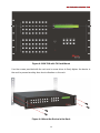
Figure 5-6 MX-7UB Rear Panel (32 I/O Jacks)
The input terminal channels supply you to connect to different equipment including
Blu-ray/DVD players, graphics workstations, and number displays. The output jacks
allow you to connect to extensible accessory devices for over long connections with
terminals just like projectors, video recorders, displays and multiplexers and so on.
Power Port: The Power Port is applicable for 100~240VAC, 50~60Hz connected to
the outlet of power source. Refer to 6.5 Power Connection
.
Power Switch: To switch power ON or OFF the Matrix Switcher.
RS-232: Use a 9-pin RS-232 cable to connect both computer serial port (COM1 or
COM2) and Matrix Switcher RS-232 communication port, refer to 6.3.1 RS-232. The
computer then can be deployed to control the Matrix Switcher after installing of
application software.
LAN Port: Use the RJ45 connection cable to connect the Internet and the Matrix
Switcher. The entire PCs at the same network can control the Matrix Switcher
through the LAN port. Refer to 6.3.2 RJ45 LAN Port.
Switchers: Matrix Switcher supports 8 pins DIP for connected configurations. For
more information, refer to 6.6 DIP Switcher

M
M
M
X
X
X
-
-
-
3
3
3
U
U
U
B
B
B
/
/
/
M
M
M
X
X
X
-
-
-
4
4
4
U
U
U
B
B
B
/
/
/
M
M
M
X
X
X
-
-
-
7
7
7
U
U
U
B
B
B
18
IR EXT: This is used to connection the IR Receiver Cable for the Matrix Switcher
Remote Controller. Refer to…
IN Ports: Matrix Switcher HDMI Input jacks are connected to the Blu-ray players,
DVD players, STBs or other source devices.
OUT Ports: Matrix Switcher HDMI Output jacks are connected to HDTVs, projectors
or other sink devices connection.
HDMI Type A: Pin Definitions:
Pin # Signal Pin # Signal
1 TMDS Data2+ 11 TMDS Clock Shield
2 TMDS Data2 Shield 12 TMDS Clock-
3 TMDS Data2- 13 CEC (NC on device)
4 TMDS Data1+ 14 Utility (NC on device)
5 TMDS Data1 Shield 15 DDC-SCL
6 TMDS Data1- 16 DDC-SDA
7 TMDS Data0+ 17 DDC-Ground
8 TMDS Data0 Shield 18 +5V Power
9 TMDS Data0- 19 Hot Plug Detect
10 TMDS Clock+
IR TX Ports: Used to connect to the IR Blaster Cable for IR pass-through.
Figure 5-7 IR Blaster Pin Definitions
IR RX Ports: Used to connect to the IR Receiver Cable for IR pass-through.
Figure 5-8 IR Receiver Pin Definitions
TX/RX IR EXTENDER Ports: Reserve

M
M
M
X
X
X
-
-
-
3
3
3
U
U
U
B
B
B
/
/
/
M
M
M
X
X
X
-
-
-
4
4
4
U
U
U
B
B
B
/
/
/
M
M
M
X
X
X
-
-
-
7
7
7
U
U
U
B
B
B
19
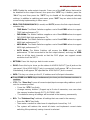
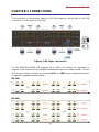
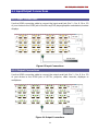
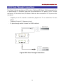
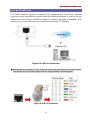
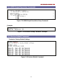
CHAPTER 6 CONNECTIONS
The connection is described as below for MX-3UB reference, the MX-4UB or MX-7UB
connection is as the same as MX-3UB.
Figure 6-1 MX Series Connections
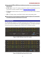
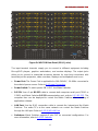
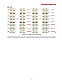
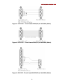
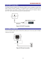
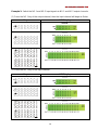
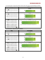
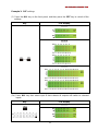
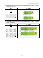
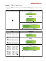
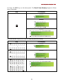
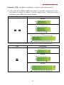
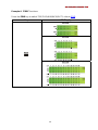
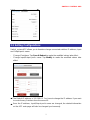
The MX-3UB/MX-4UB/MX-7UB supports up to 4/8/16 I/O modules for reparation or
upgrade. Each module can be configured individually based on module number. You can
search these module numbers by pressing PLUG and INFO keys simultaneously when
you want to upgrade firmware version.
MX-3UB:
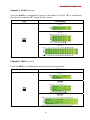
MX-4UB:
Page is loading ...
Page is loading ...
Page is loading ...
Page is loading ...
Page is loading ...
Page is loading ...
Page is loading ...
Page is loading ...
Page is loading ...
Page is loading ...
Page is loading ...
Page is loading ...
Page is loading ...
Page is loading ...
Page is loading ...
Page is loading ...
Page is loading ...
Page is loading ...
Page is loading ...
Page is loading ...
Page is loading ...
Page is loading ...
Page is loading ...
Page is loading ...
Page is loading ...
Page is loading ...
Page is loading ...
Page is loading ...
Page is loading ...
Page is loading ...
Page is loading ...
Page is loading ...
Page is loading ...
Page is loading ...
Page is loading ...
Page is loading ...
Page is loading ...
Page is loading ...
Page is loading ...
Page is loading ...
Page is loading ...
Page is loading ...
Page is loading ...
-
 1
1
-
 2
2
-
 3
3
-
 4
4
-
 5
5
-
 6
6
-
 7
7
-
 8
8
-
 9
9
-
 10
10
-
 11
11
-
 12
12
-
 13
13
-
 14
14
-
 15
15
-
 16
16
-
 17
17
-
 18
18
-
 19
19
-
 20
20
-
 21
21
-
 22
22
-
 23
23
-
 24
24
-
 25
25
-
 26
26
-
 27
27
-
 28
28
-
 29
29
-
 30
30
-
 31
31
-
 32
32
-
 33
33
-
 34
34
-
 35
35
-
 36
36
-
 37
37
-
 38
38
-
 39
39
-
 40
40
-
 41
41
-
 42
42
-
 43
43
-
 44
44
-
 45
45
-
 46
46
-
 47
47
-
 48
48
-
 49
49
-
 50
50
-
 51
51
-
 52
52
-
 53
53
-
 54
54
-
 55
55
-
 56
56
-
 57
57
-
 58
58
-
 59
59
-
 60
60
-
 61
61
-
 62
62
-
 63
63


AVLink MX-3UB Owner's manual
- Category
- Video switches
- Type
- Owner's manual
Ask a question and I''ll find the answer in the document
Finding information in a document is now easier with AI
Related papers
-
AVLink HX-2544 Owner's manual
-
-
-
-
-
-
-
-
-
Other documents
-
 Zigen HX-88 User manual
-
 Sunbox VHW0404KA User manual
-
 StarTech.com Converge A/V 4 to 1 HDMI Switch User manual
-
 infobit iMatrix H44VAW User manual
-
RocketFish RF-G1501 Quick setup guide
-
Clare Controls HDBaseT 32x32 User manual
-
 A+V Link Technologies AVM-6996H-SYS-A3 Quick Setup Manual
-
DigitaLinx DL-HDM44 Installation guide
-
-
Lindy 6x2 HDMI 2.0 18G Matrix Switch User manual


